


BANYAN
-
Posts
5,534 -
Joined
-
Last visited
Content Type
Profiles
Forums
Gallery
Events
Everything posted by BANYAN
-
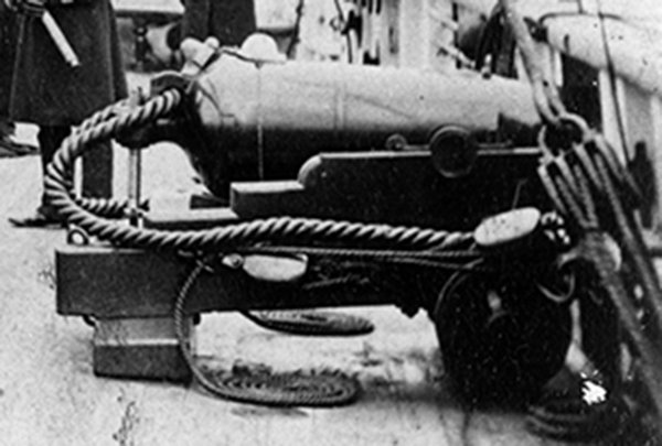
Hi Bob, agree your reasoning WRT using such coils. These coils may have been a bit more commonly used than perhaps thought. Further to Bob's comments, even in this day and age (well when I was in the service at least) where synthetic cordage is commonly used (and more prone to the effects of UV), these decorative coils were in common use for rope whenever the ship was in harbour/at the buoy or at anchor. When underway 'proper' working coils were always used. These coils are also evident in images of HMCSS Victoria (1855). It appears this may have been the general practice in RN ships (or military type ships) back then also, as can be seen in the following photograph (c.1858) of the gun tackle working parts being cheesed (or more correctly - Flemish coiled). The vessel was in harbour (moored) at the time. However, I must offer a point of difference in opinion WRT to how they were unwound. When reforming the coils, or taking the coil in hand, we would 'unwind' it from out to in by grasping the rope/line near the block or securing device, then walking the line out. This was the opposite to the way it was made up, which minimised the risk or tendency of the rope to kink, and allowed the rope to unwind with its lay. That said, other Services/ships may have done it differently. cheers Pat
-
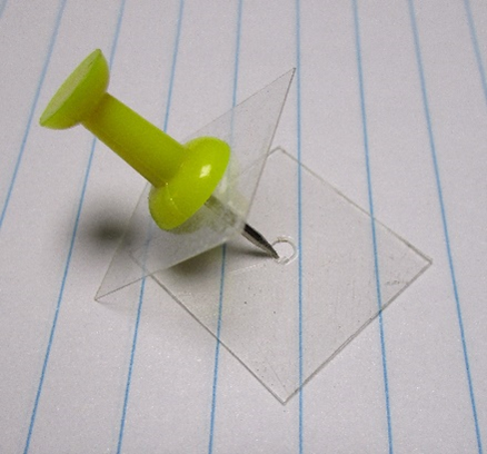
Hi Vossey, I will try to describe the technique I use for 'cheesing' the tail ends of tackles. Not my original idea, but it works well for me. First soak your rope/thread, cut to an appropriate size (if doing separate) in a diluted solution of PVS/water ( I use about a 60 water/40 PVA). If using the actual tail end of the tackle, this still works but just soak the required length of the tail (working end of the falls) I use two small squares (or round) of clear plastic (from shirt boxes or the like). I punch a pin (usually a tack with raised plastic head) through both (See Photo). Separate the two leaving the upper plastic square/round on the pin, and put the outer/tail end of the rope/thread through the centre hole of the bottom square with about 1 to 2mm protruding to the bottom side. Put the pin back into this such that it holds the end and makes a sandwich with the thread between both plastic squares. Now rotate either the assembly or wind the thread around the centre pin to start making a flat cheesed coil to the desired diameter. Allow the finished coil to dry before removing; the plastic does not let them stick too much but still take some care when separating the coil from the plastic. These 'jigs' are so easy and cheap to make you can dispose and remake as required, especially when the centre holes become too large from wear/use. Just one way to do it. cheers Pat
-
 Great way to rekindle those memories Mark; good luck with this project. cheers Pat
- 4 replies
-
- 3
-

-
- half hull
- half hull planking project
- (and 1 more)
-
What a great result Eberhard; thanks for stepping us through the process. It looks very effective/realistic, especially at that scale. cheers Pat
-
A stunning build Richard; an exemplar of how to build such a model. I have very much enjoyed this build log so far. cheers Pat
-
You continue to show us just what is possible with your metal smithing Keith; impressive results. cheers Pat
-
That is some 'plodding along' Ian, looks great. cheers Pat
- 502 replies
-
- 4
-

-
-
- Quadrireme
- radio
- (and 1 more)
-
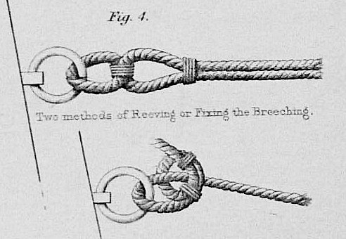
Agree, the following is from Capt. Boxer's (RN) 'Diagrams of Guns' (1853) which still shows the use of bending the breeching rope to rings in the mid-19th century. cheers Pat
-
Great to see this update Jason; your build continues to impress. cheers Pat
-
Great diorama Greg; have to agree that wake looks really convincing. cheers Pat
- 47 replies
-
- 1
-
-
- Zumwalt
- Snowman Model
- (and 2 more)
-
Nice work Jerry, looks great. I like the printed 'races'/tracks. cheers Pat
- 524 replies
-
- 2
-
-
- sloop of war
- constellation
- (and 3 more)
-
Hi Ian, I cannot recall where now, but I managed to buy just a few sheets from an online supplier. If I find some time, I will dive into my records to see if I can find the supplier - but I am not hopeful. cheers Pat
- 502 replies
-
- 3
-
-
- Quadrireme
- radio
- (and 1 more)
-
Ian would not a self-made decal work to maintain the uniformity of the eyes. The decals, once applied, can be sealed with a spray-on or brushed varnish /clear coat for protection. I have had success printing my own decals for small toys etc that I make for the grandkids. The decal paper is relatively cheap and readily available online. I printed mine using a laser jet printer, but I think there are decal papers for other types of printers also. That said, hand painted adds a sense of realism. cheers Pat
- 502 replies
-
- 4
-
-
- Quadrireme
- radio
- (and 1 more)
-
Hi folks, does anyone know if Donna has returned to the business yet? I have tried contacting her several times (two different email addresses) but have not heard anything back. Grieving can take a while to come to grips with, and I fully understand if she has decided not to return yet - simply asking. I do not wish to pester her with emails until she is comfortable. cheers Pat
-
Eberhard, I think a lot of this can be deduced from the various issues of the 'rules' from Trinity house. cheers Pat
-
Folks, there may be a bit of a mix of terminology being used here? If not, apologies in advance. As most of you know I am researching the rigging for HMCSS Victoria (1855) which may help shed some light on the question. Victoria's Specification, and her Rigging Warrant, both mention wire rope vertical jackstays (separate to the shrouds). As far as I can establish, the vertical jackstays (also sometimes referred to as horses I think) were (in Victoria at least) used to lace the leech of the storm sails. In Victoria, the fore, main and mizen (driver) fore-and-aft sails used traversing hoops. I have read that the jackstays were also used in some ships to lace the leech of all fore-and-aft sails rather than using hoops. From what I have found so far (and I would still welcome further info about the subject) is that these were either rope (early versions), wire rope or even iron rod (later ships). I have not established how they were secured on their upper and lower ends. In Victoria, I think these were only rigged when the storm sails were bent on. As such the vertical jackstays did not have footropes. While Paul is referring to the shrouds, vertical jackstays may also have been used in Flying Fish which may be the cause for the mix of terminology - @paul ron do your rigging/belaying plans also refer to vertical jackstays? cheers Pat
-
I'm with Roger; I prefer the use of fine pointed irons, but in my case I use resistance soldering. WRT silver solder (the item not the technique) I use products that are for different melting points with no issue. However, as some have pointed out/suggested, these may not be true silver solders but rather solder with silver rather than tin content. Either way and pedantics aside, I find them much stronger than normal soders, and the differing melting points in conjunctioon with the ability to dial up or down the level of resistance (heat), I find I can deal with very small parts effectively. cheers Pat
-
Wonderful work Eberhard; a stunning micro-model. I have enjoyed following this build tremendously. cheers Pat
-
Hi Keith, I may need a reminder, but I had to research this a little for the Victoria also. If I remember, I will send you something by PM next week as I am up to my neck in alligators at the moment and away for the long weekend. Basically, there were some Rules and Regs introduced by Trinity House (London) in and around the mid-19th century WRT to safety, including lighting in steam-powered ships. Whether, the US ships adopted these I do not know. Effectively from about 1858 (I think) steam-powered vessels were required to show various lights at night and in poor visibility - basically the forerunner of today's colregs. Initially, I believe these were simple light boards or just lanterns hoisted into the mast tops, or lashed to the shrouds. cheers Pat
-
You're well and truly making up for the 'no dust' in earnest now Keith. That hull looks 'speedy' - very nice lines. cheers Pat
-
Nice shots John, really shows off the fine work you have done in the framing. cheers Pat
-
Won't take long; he already shows an air of concentration. A very handsome young chap! cheers Pat