


Snug Harbor Johnny
-
Posts
1,383 -
Joined
-
Last visited
Content Type
Profiles
Forums
Gallery
Events
Posts posted by Snug Harbor Johnny
-
-
The Antikythera mechanism (found in a roman wreck that sank ca. 50 BC/BCE) was essentially an 'Earth Centered' Orrery - since earth was thought by most to be the center of the Universe back then. There are many nested shafts and some complex gearing, like that which approximates the changes in the moons orbital speed (they did not know of the ellipse then). Several modern reconstructions have been made with modern gear forms to reduce what amounts to awful backlash with triangular teeth.
Ah HAH, (again) ... I realized that I have the BOTTOM of the kit box from Billing Boats, and it only measures 22" wide. With an inch needed for clearance/packaging, a full-length single keel wouldn't have fit for a true 1:100 Vasa. 'Kind of looks like something 'rear ended' my model ... but it still has the appeal of a miniature.
- clearway and Knocklouder
-
 2
2
-
'Looks like you don't need much of a bend to meet the curve of the deck. Suppliers are VERY unlikely to use lead-containing alloy these days (which easily bend), for one thing, it is likely illegal. That leaves zinc the likely material, which can be brittle depending on what "else" there is in the alloy.
A form could be made with just a little (and I mean little) more curve than what you need, and there has to be portions cut or filed out where those vertical thicker areas are shown in the photo. Only the thin area of the cast bulwark will contact the wood of the form. You can heat the cast metal in boiling water, since the only alloy I know that melts in boiling water is 'Woods alloy' (used for sprinkler heads and 'trick' spoons).
The warmed metal can then be gently pressed against the shallow curve of the form with a gloved finger or palm.
-
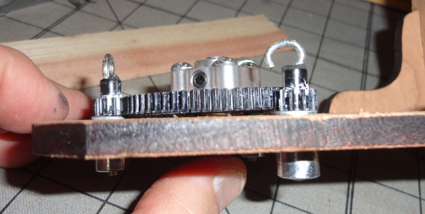
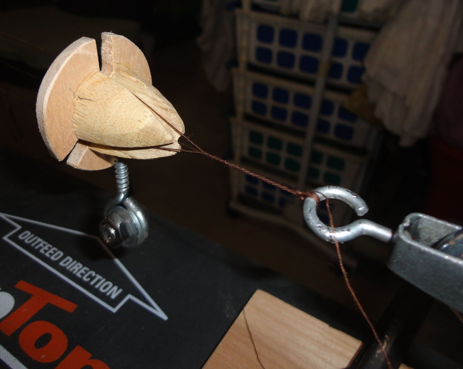
To clarify what I said about a rope maker's "top", a photo is shown below. The 'top' itself looks looks a child's toy top (on its side), and I've added a wooden flange to make sure the strands don't jump out of the notches. There is a weight on the bottom to keep the 'top' from spinning (like a top), which would twist strands on the other side (not desired). On the full size rig, the tension from twisting the strands is enough to make the rope form 'all by itself' - and the 'top' moves back automatically as the rope is formed by counter twist. On the mini rope walk, it doesn't work due to friction on the small turnbuckle, etc. - hence a motor on the second end would be needed to make the process a 'one step' operation ... perhaps helpful for someone wanting to make large quantities to sell.

Now for an "AH - HAH !!" moment. - at least concerning the present build. When the major changes to the stern were made, only the first two cannon aft of the main mast were exposed on the weather deck (the next two being under a higher deck). This was always the case as the framing for the 1:100 model was built 'out of the box' some time ago. But the Vasa had 4 cannon on the weather deck aft of the main mast.
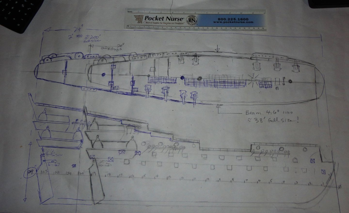
The problem with THIS kit is that the length of the hull is not to the stated scale, even though the beam and fittings ARE to scale. The Vasa hull is 201 feet (without the bowsprit ... 228 feet with bowsprit - a very large ship for its day) and the beam (max) is 38 feet. OK, for ease of calculation I'll use 200 feet (alright, we Americans are still hooked on the 'English' system rather than the metric used by the rest of the world) for just the hull.
There are other lengths one can fine, such as 'at the waterline' or 'between perpendiculars' ... but at the stated scale of 1:100, a 200 foot hull would scale down to (duh) 2 feet or 24". My Vasa hull is only 20 inches !! A 38' beam scaled down (1:100) should be about 4.6" ... and my model is just that. So width-wise (and fittings-wise) its OK at 1:100, but the length is 4" SHORT. Was that a goof back in the 60s when the kit was designed? Or were there other reasons, like having the plywood keel fit into a certain sized box? (The box was lost long ago.) Or was it 'cloned' from another kit design - like the Norske Love ?
Sure, things were corrected in subsequent editions (at a 1:75 scale), but short of sawing-off the end of my partially complete model (which I might have been tempted to do before getting as far as I've come to date), splicing in 4 inches of keel, making 2 additional frames and adding planking to blend with the aft portion to 'stretch' the model ... there is no reasonable way to have corrected the anomaly.
I've made a rough sketch of my model size in pencil, and ADDED in blue ink what the profile 'should be' at 1:100. THEN, the cannons on the weather deck would be right, as well as the position of the stern walkways, etc. Tisk, tisk - no stopping now, and I think I'll have a reasonable impression of the Vasa when done (as mentioned before in this build) ... art imitating life. And I'm learning a lot about the hobby in the meantime.
The 'long', high-sterned configuration of the Vasa likely made it more 'canoe-like' in behavior (heavy armaments and high masting didn't help either). It is said that more beam would have permitted better ballasting, ergo more stability. The current day kits (Corel and Billings) are 1:75 should have about a 32" hull ... a pretty large model to make, and the Artesania Latina at 1:65 should have about a 37" hull - a whopper.
-
1 hour ago, clearway said:
Hope it all works out in the end- this goes to re-estabilish why i never went down the rabbit hole of scale model rope making😉
Keith
Actually, I was almost making it into a rabbit hole by pondering how to "improve" (or speed) the process. As provided, Chuck's Rocket does a decent job as a two-step process. One just needs to pick a preferred material and see what diameters are produced by varying the number of threads used on each of the three lengths spun.
As far as rabbit holes are concerned, I try to back out off them in most cases. The one that almost got me good was trying to figure out how to make my own replica of the Antikythera Device ... google that.
Johnny
-
'Spent a couple days trying to get a miniature rope makers' "top" to work - and thereby eliminate step 2 of the Rope Rocket method (as designed). Seems that the very small size of the material being spun does not 'scale down' like what I've used on full size rope when I have demonstrated rope making as a period craft.
With too much friction preventing the automatic generation of counter-twisted mini rope (even trying a roller bearing for the central hook), I'd need a motor mounted on the second end of the rig - activated by a foot pedal ... and I've delayed further progress on my build as it is. Perhaps my R&D in this area will be continued another time (would be cool though).
Meanwhile I noticed that for every turn of the large gear on the 'business' end of the Rocket turns each planetary gear about 6 1/4 times. My first drill had a VERY high rate of speed, so I got a lithium battery powered 'drill/driver' at Harbor Freight ($19.99 !) to have better control of step one of the process. I first went to a 'big box' store to look in their tool department, and they had nothing under $100. But $19.99 ? ... No way it could be made in the U.S. and sold for a profit at THAT price. Then again , in retirement, I have to look for 'bargains' ... but have we made a 'Devil's bargain' that has hooked us on low prices for consumer goods? It's still Lent, so I should do a little more Penance.
But I've digressed, the SECOND step of the Rope Rocket is to spin the other end ... but there is no gearing there, so for every turn of the drill head there is one 'counter turn' to twist the tensioned strands into rope. The initial twisting of the strand in step one needs to be countered by about an equal number of counter turns in step two ... so if the drill head speed is the same as used on step one, then it will take about 6 times longer to complete step 2 (compared to step 1). THAT is why I used the FASTER drill (somewhere between 2 and 3 times as fast) for step 2, so it only take a little more than twice the turning time of step one.
After a few tries with the normal 'learning curve' it is a straightforward procedure that I find relaxing. For a given limit of your mini rope walk, there will be an ideal amount to let the geared head move forward (judging the 'tension' with one's primary hand - right or left, so the walk is set up either way as desired) - in my case about 18", while the other hand applies the drill. BTW, I needed to use a large 'blunt' phillips drill bit to best fit the indentation in the provided bolts. My rope walk will make about 7 paces (about 1 yard per pace) of finished rope each time. This works out to about 700 yards 'in scale' at 1:100 !
In step 2, the other end of the Rocket DOES move back (longer) a little (8 - 12 inches depending on the thickness of rope being made (as noted in my last post), and it does move back forward just a little - the 'feel' being judged by hand (as that end has been unclamped) - but with opposite hands to the first step. I'm not ambidextrous, so rope making with the Rocket is no big feat. When the rope is twisted nearly to the end, I stop.
The end is cut and knotted over itself, and I'll pull about an arms-length to 'set' the rope (no need to bother with water when using Metrosine polyester thread) and let the end dangle. If there was not quite enough counter-twist, the hanging end of the mini rope will 'twirl' clockwise a bit (the same direction as done in step 2, which 'appears' counterclockwise when looking down at the dangling end). Only if over spun will the end twirl the other way. When I 'get it right' there is almost no twirling. When I saw the rope makers working at the Goshenhoppen Folk Festival, they counted the number of turns on side one of their rig, and the man (or lad) at the other end counted the same number of counter twists since their second end was geared the same as the end with the spinning heads (planetary gears).
When doing demos myself, I never did anything quite the same twice, but let the unrestrained single hook (swivel) at the far end 'do its thing' as the rope maker's "top" ran up the run like a juggernaut. When done, I just 'shook out' the rope to remove any residual twist imbalance, then tied an end around a post or tree so I use my body weight to 'set' (or stretch out) the rope. The best rope was from hemp (which I found rather expensive), so I had to switch to jute, which was OK. Sisal is lousy.
Anyway, I'm happy with what I can make with the Rope Rocket since I can control the color, thickness and material used.
- clearway and Knocklouder
-
2
-
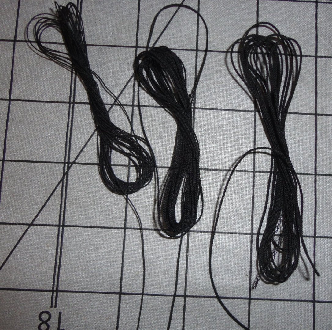
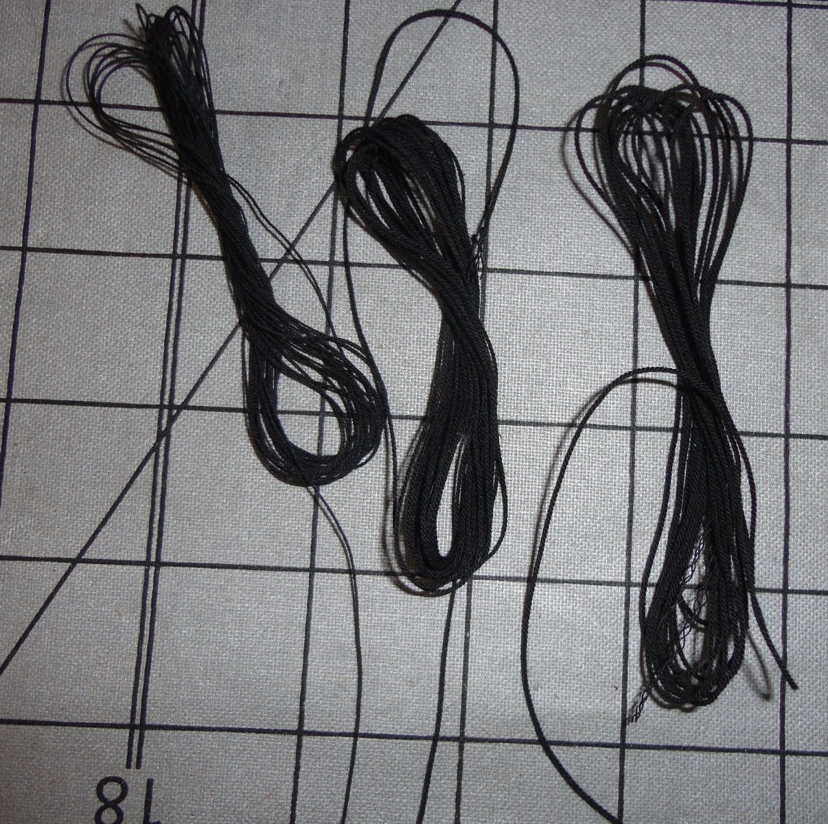
'Thought I'd make some rope to approximate scale, as the various spools of kit ropes on hand vary in quality. It would be best (given the trouble gone to so far) to have as much as needed made up on the Rope Rocket for consistency. I started with black for standing rigging using a good polyester (same as I use for tricorn hat making) brand - Metler's "metrosene". We know that cotton or silk can have some age related problems in the 60 - 80 years range, depending on lighting and atmospheric conditions. Linen line is the old standby, but polyester (with pros and cons related to glue use on model applications) is likely to have a very long life.
With 3 threads wound in each of the 3 strands on the Rocket, the line (after stretching by hand to 'set' the rope once made) measures .030" in diameter ... representing about 3" diameter rope on a 1:100 model (my Vasa scale). This will be used for some of the fore stays. With 2 threads per strand, the diameter is .022 - representing about 2.2" diameter rope for shrouds, backstays and higher fore stays (and heavier running rigging in a tan color). Single thread strands make .012 rope - for ratlines, running rigging and lacing the dead eyes.
I'm taking a 'shortcut' for seizing dead eyes by tying a small 'hangman's noose' and snugging it on the dead eye ... Then it struck me that BLACK may not be the best for this build (fine for clippers and many later sailing ships) ... but rather a dark brown as I've seen used elsewhere. So I went out and bought 2 shades of brown to compare - one a raw sienna and the other closer to burnt sienna. The raw sienna may best represent rope treated with the concoction often used to promote better service life. Some note that ropes so treated would darken further with use, but the Vasa didn't get much 'use' ... what, 20 minutes?
BTW, there is another 'rope making' "kit" sold for ship modelers ('forgot the name, and don't care to remember it) that I tried before finding out about the Syren product ... What was supplied with the 'other' device would not 'go together' without a LOT of tinkering and re-engineering - and a hand cranked device is NOT the way to go, as it takes AGES to get a decent amount of product (and a sore arm as well).
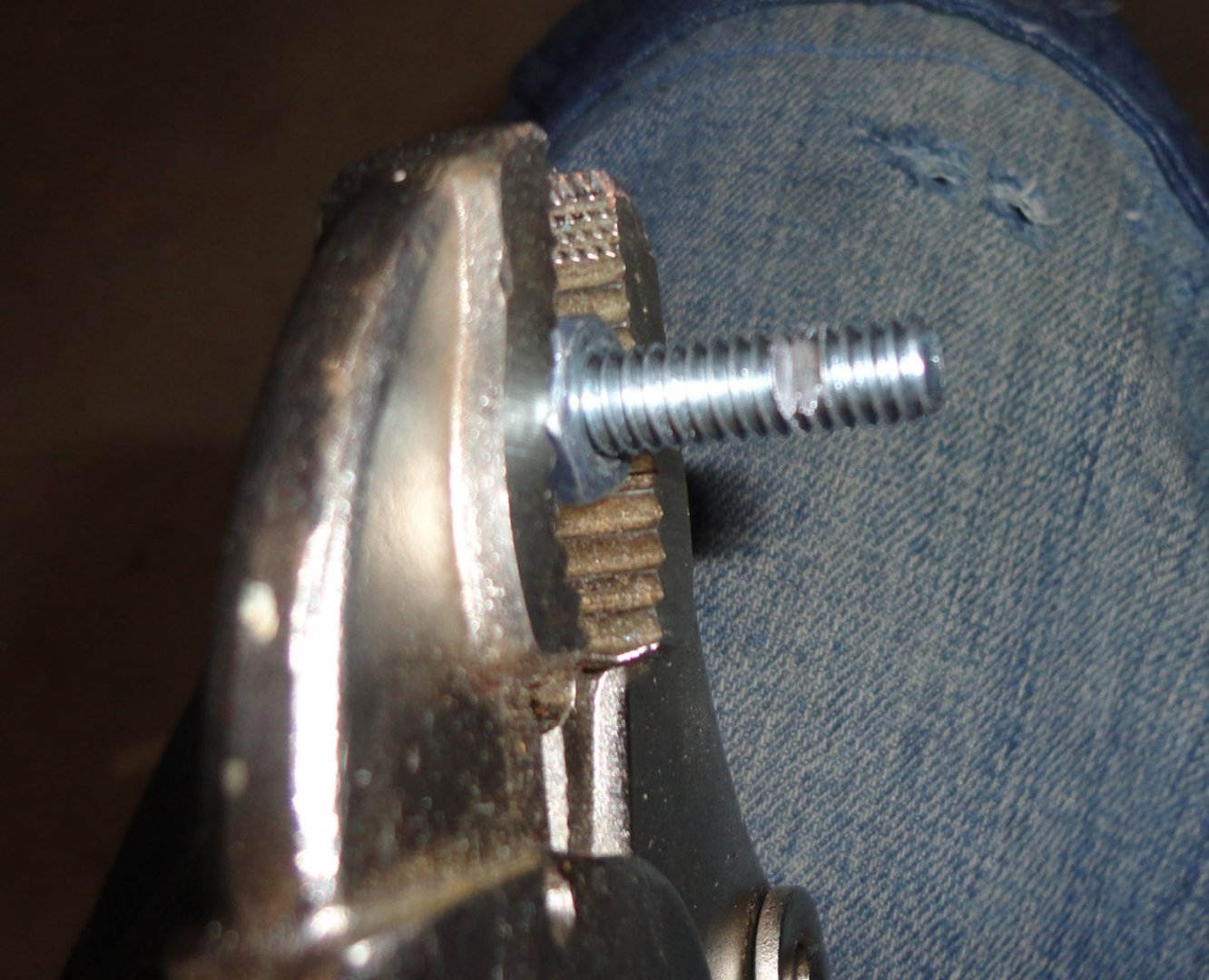
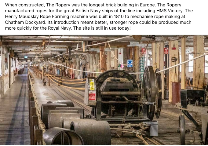
Now I did run into something with the Rocket, relating to a set screw having the function of locking a drive bolt to the central gear assembly. One should only tighten a set screw 'so much' ... as to avoid stripping threads in the housing (set screws come hardened), yet the drive bolt is itself a 1/4-20 threaded bolt. What happened in my case was that as tension built, I may not have moved the geared end forward far enough (refer to the You tube on how to use the Rocket ... really, its not 'rocket science' ) - and the drive bolt 'screwed itself' past the set screw somewhat (due to excess tension?).
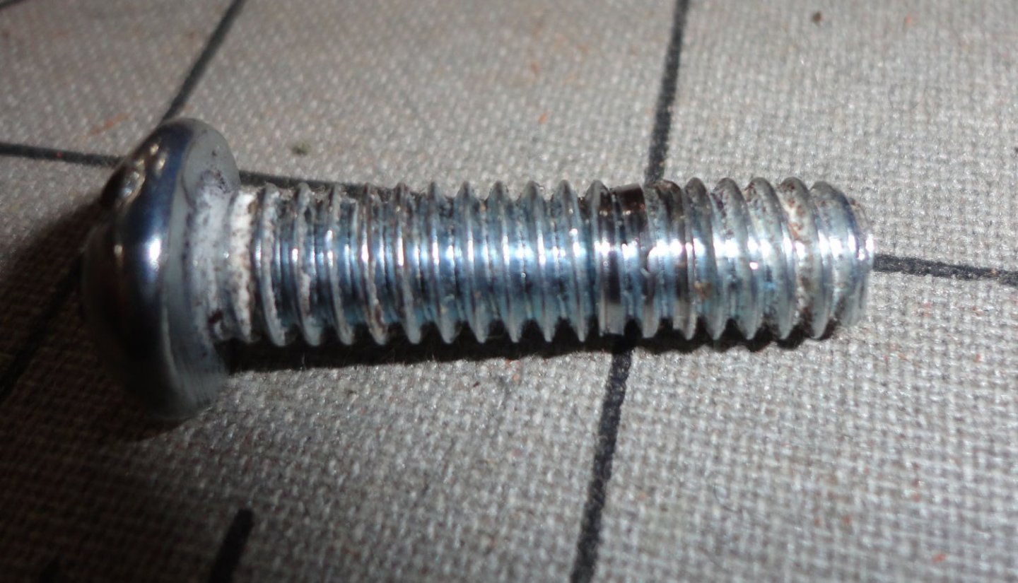
This eliminated clearance between the moving parts (pulled everything together, actually) and friction increased enough that the Phillips head bit in the electric drill stripped the head of the drive bolt as shown below.
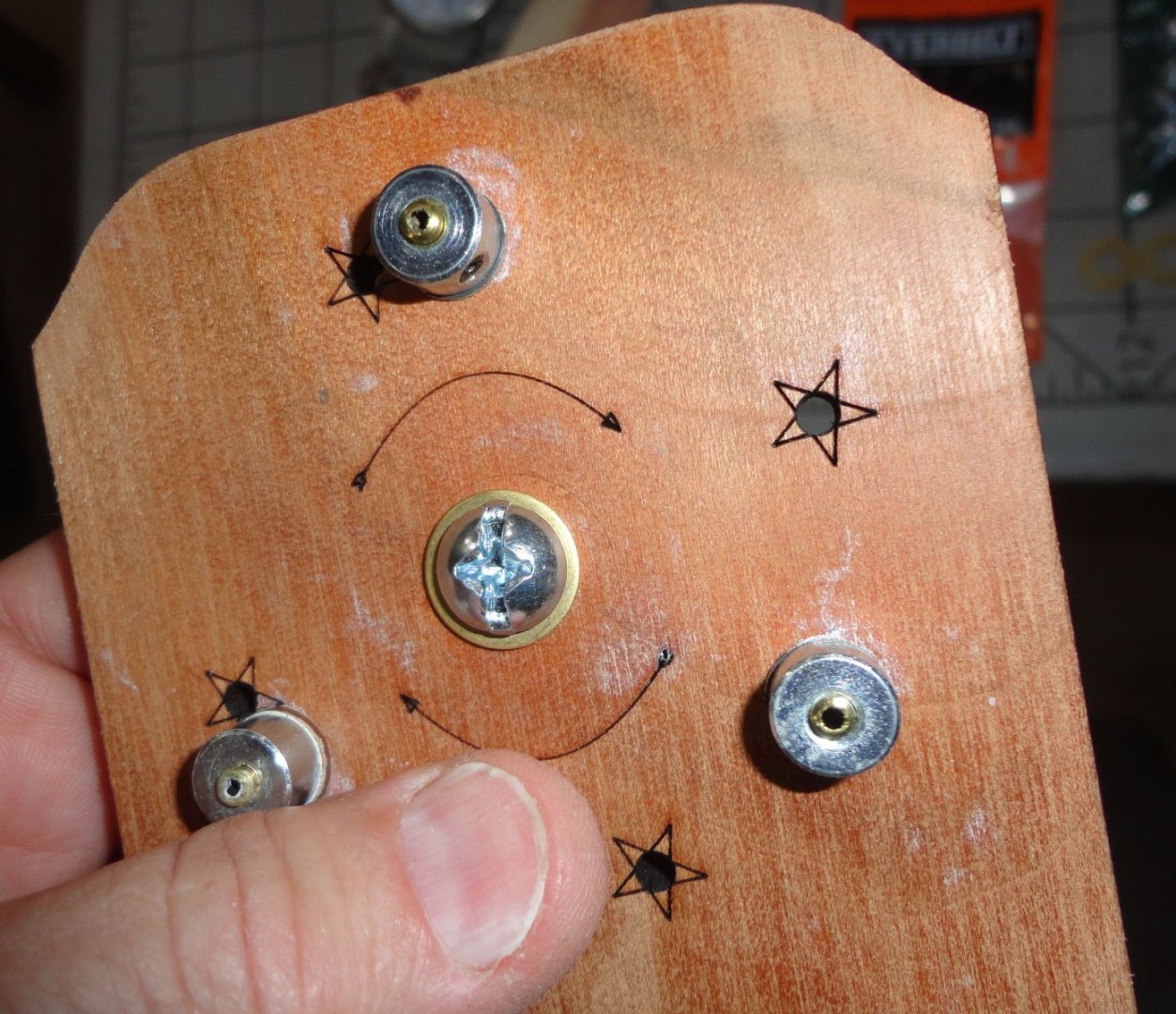
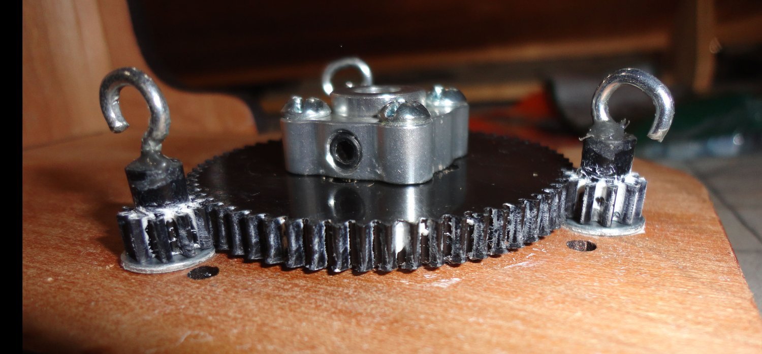
So I realized that what was needed is a 'flat' filed on the side of the drive bolt to give the set screw a better surface to grip - one that won't allow the bolt to shift . This was also the time to see if there were any other changes that might improve functioning. I noticed that the planetary gears all had small washers (the drive bolt has a large washer) - but the central gear didn't have any washer (as supplied). This caused flexure in the middle when everything was pulled tight - but delrin (the presumed gear material) does have some 'give' to it.

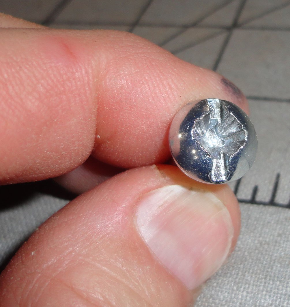
When I took off the central gear, it was obvious that bolt ends from the hub had gouged a circle where they protruded slightly through the central gear. These bolts engage the gear to spin it. As I decided to add a brass washer with a diameter less than the bolt circle of the hub, it was not necessary to file the bolt ends ... but something that can also be done when first building.
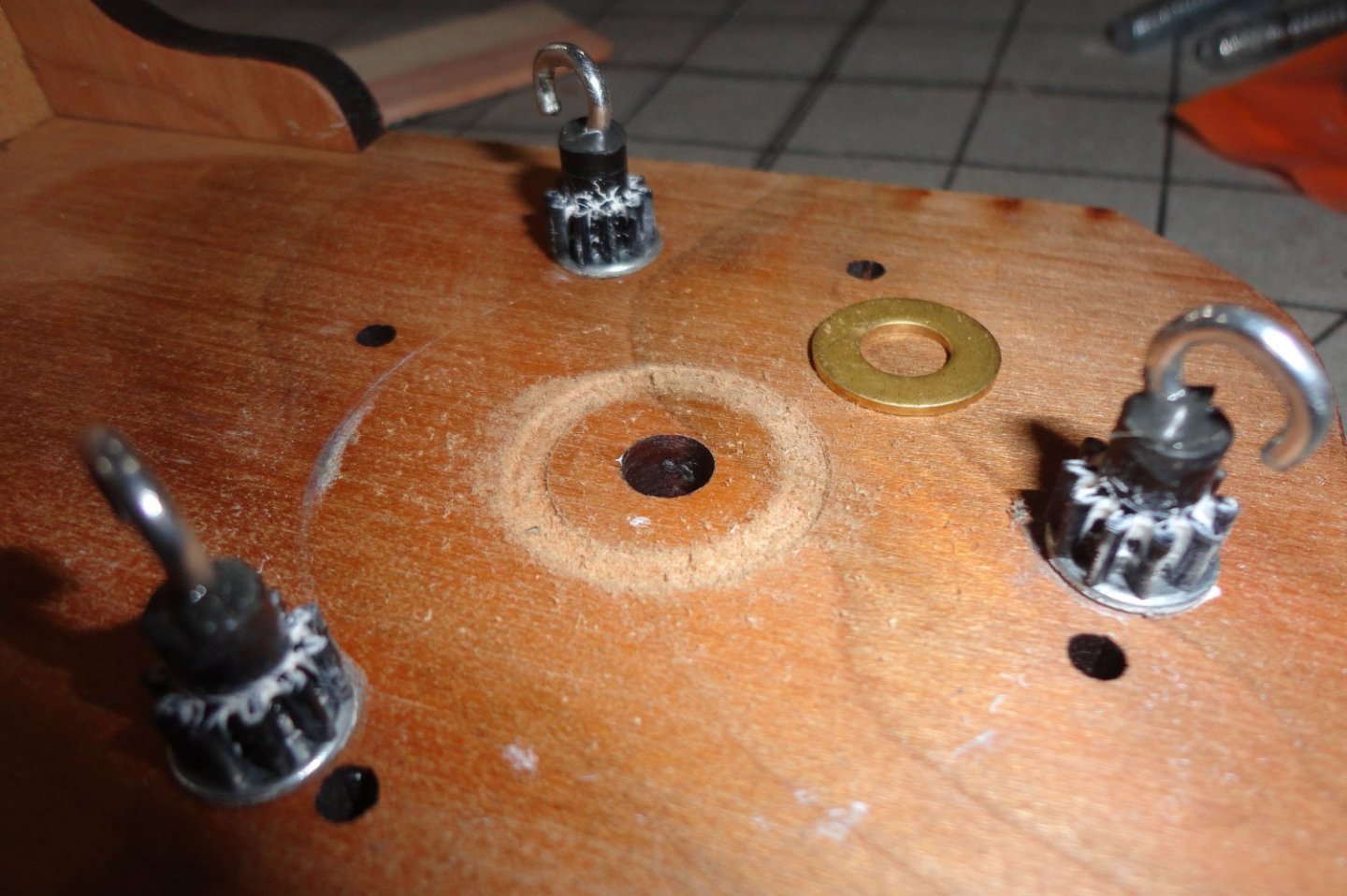
Below is the underside of the central gear showing slightly protruding bolts.
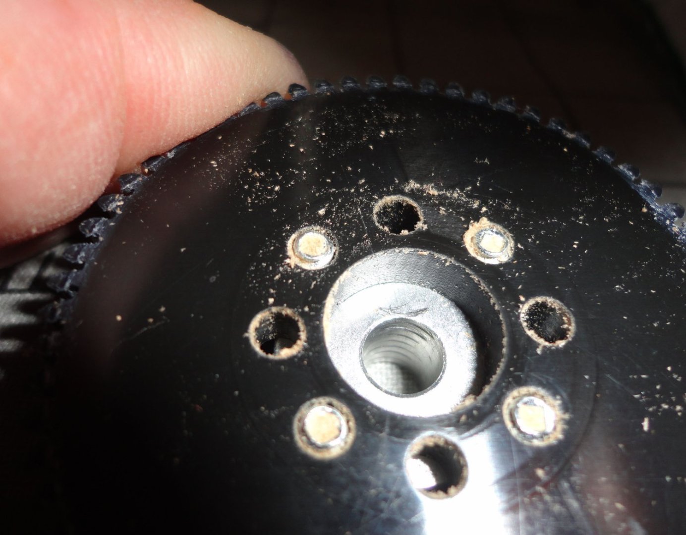
No matter, the brass washer sandwiched itself nicely when re-assembled. The drive bolt (when assemble from the back) will align everything properly.
There was a test assembly and the set screw was tightened to 'dink' the threads of the drive bolt to mark where the flat needed to be filed. I used a nut and vise grips to hold the drive bolt while filing a flat for the set screw to grip.
The everything was assembled and tightened. I used white lithium grease as a gear lubricant, and clock oil elsewhere.
Now we're 'good to go' ... and I made some nice rope on it. The idea is to (rough) pre-lace the dead eyes before mounting on the hull. After the first mast sections are in place, the shroud ends will be looped around and CA'd (as opposed to seizing with thread under the tops where things are cramped) - with the dead eye spacing regularized by adjusting the lacing before finalizing that loop around the mast section. At least that's the plan ... we'll see how that goes.
- clearway, Ian_Grant, Knocklouder and 1 other
-
4
-
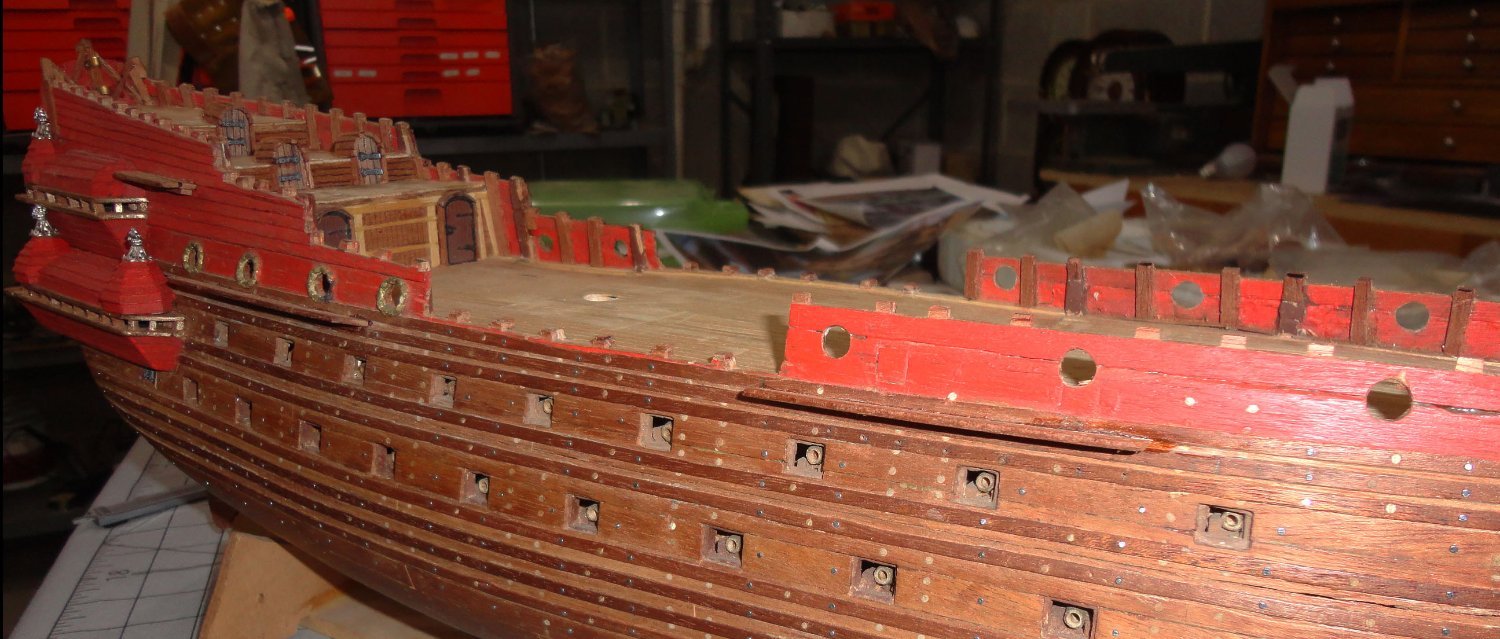
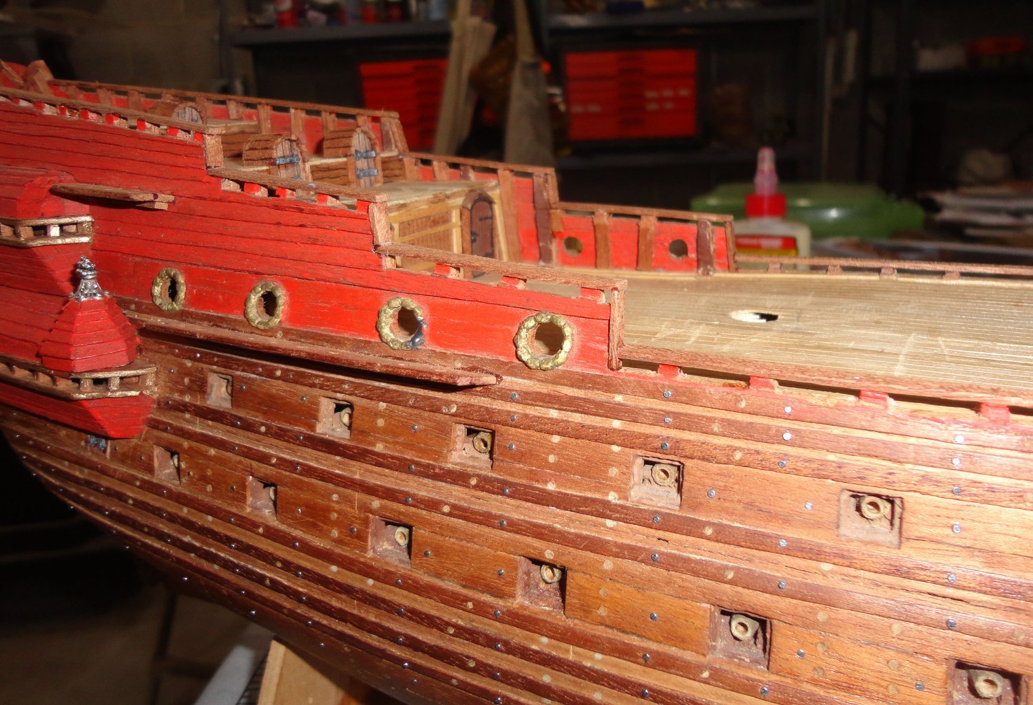
'Figured I'd have to file down the planking to let the 'ribs' be higher, then put a gunwale on the ends ... there will be light railing put on later.
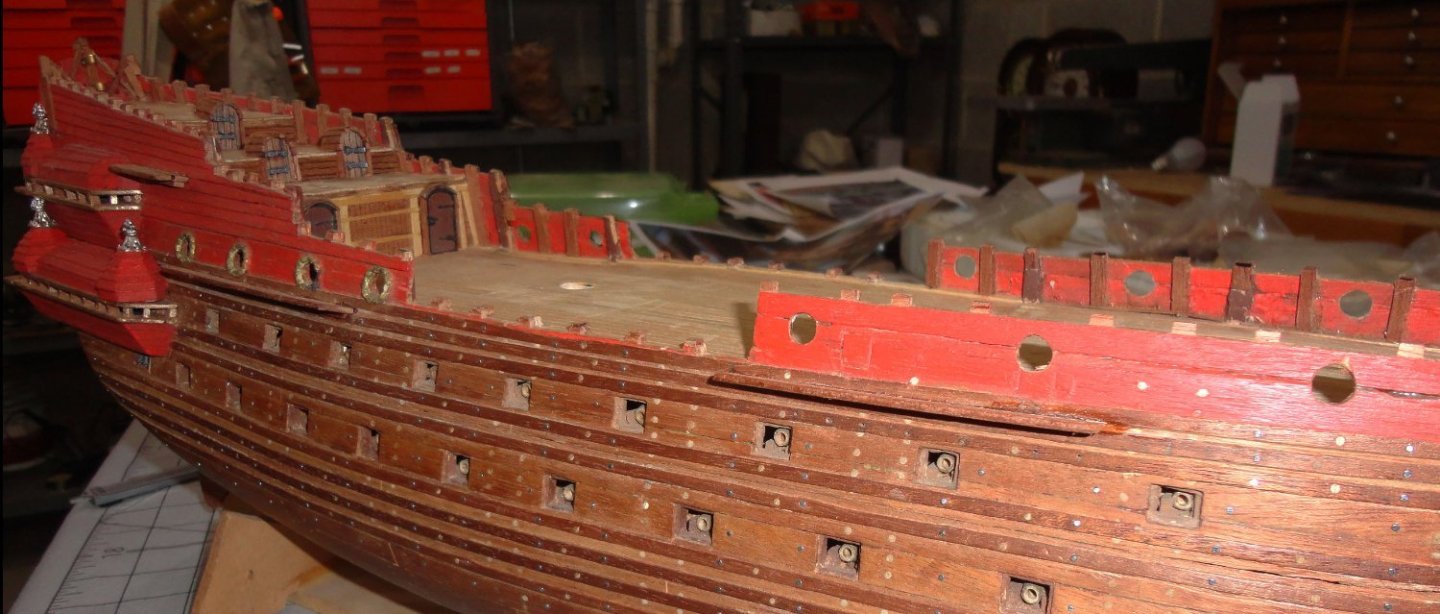
After the gunwales were added, I can see I'm one step further along this model 'rescue'. And there are now places to belay quite a number of rigging ropes. Postings on this forum indicated that belaying pins were not used on large ships prior to around 1745 ... and the Vasa is 1628. There are substantial posts with sheaves on deck for the heavy halyards, and there are also rails w/o pins ... and a few kevels, of course. So it occurred to me that the end of a rib (the original had a lot more of them than my poor model shows) would be a great place to loop a line around twice and do a half hitch. 'Just saying ...

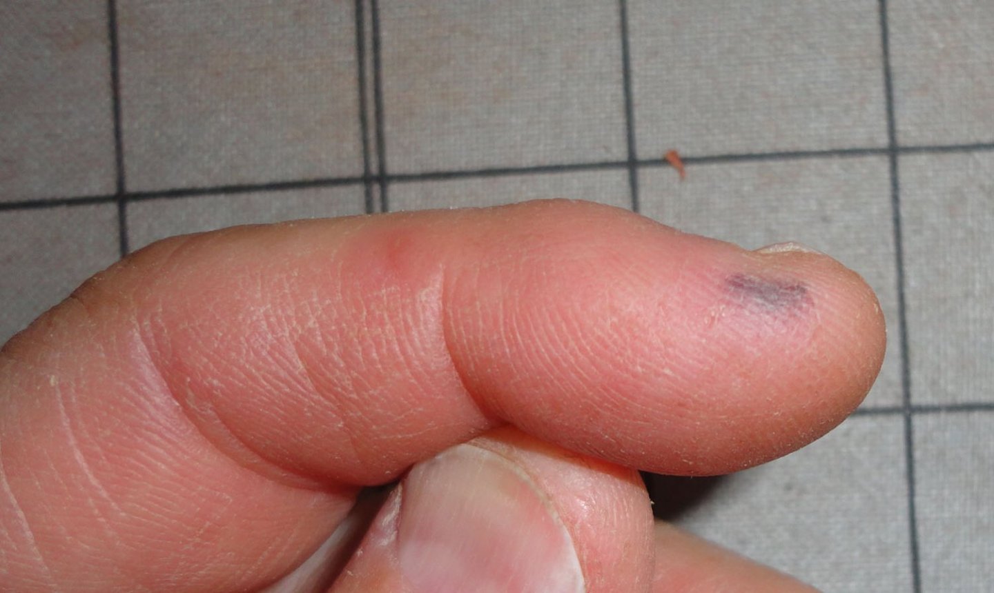
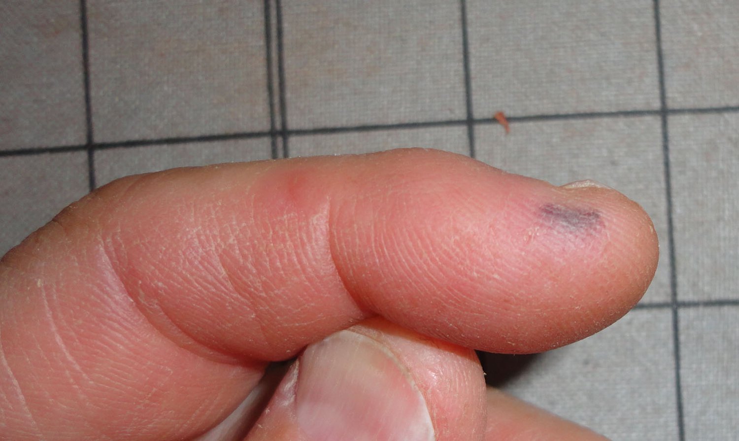
My earlier finger boo-boo healed, but a pinch just cause me a 'blood blister' ... better than a cut with thinned blood. 'Have to watch how I use pliers. Now about the lack of belaying pins - I recall a scene in 'A League of Their Own' where the coach (Tom Hanks) bawls out a player for a goof (Madonna), which makes her cry. Then he yelled, "There is NO crying in baseball ! ... There's no crying in baseball !" So I'm thinking, 'There are no belying pins on Vasa ..."
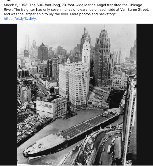
Now just two extraneous pictures stuck on my 'desktop' that I want to get off, and they might be of passing interest to forum members. The first is a tight barge squeeze.
The second is the longest English 'rope walk' ... My Syren Rope Rocket can't hold a candle to it.
Fair sailing ! Johnny
-
I did get something like this from Cornwall, but at the time I couldn't get the full quantity needed, due to the limitation of the stock they had on hand. So any supplier might occasionally have a similar limitation ... but I presume that they do re-stock when something sells out.
- Keith Black and mtaylor
-
2
-
You're going to great lengths for the lighting effects ... just be sure to check on the battery status annually, because mini 'chemical' batteries will 'leak' - actually corrode in place. You might consider using a type without the corrosion problems that have ruined many a Lionel Diesel locomotive where the batteries that ran the 'horn' (actually a bicycle horn used 'back in the day') made a mess of things.
Lithium batteries such as the ubiquitous CR 2032 might be better in the long run ... and I take it that you'd like someone to value and keep your fantastic model long after you've gone.
-
I only used hide glue for veneering. I mixed my own from granular hide glue (indefinite shelf life), and it does have to be heated. Old -time wood workers used it for furniture joints, typically tongue and groove - as well as veneering. It may not be practical for modeling use - just as the old-time bookbinders' flour & water paste has been superseded by water soluble PVA.
-
I've cut 1/64" thick brass stock into thin strips using an old fashioned long-handled paper cutter ... the kind where there is a large wooden base marked with a grid and a side-mounted blade with handle. The parent piece can have strips cut from the long edge, but when the parent piece becomes too narrow one needs a new piece of stock.
There is a small burr on the cut edges that should be cleaned up with a fine file.
-
'Looks just fine to me ...
Yeah, I did note the small 'spikes' on the bottom of the stanchions. I did get some 3D from Cornwall in England, but may save them for a clipper I'd like to build - and they were pricy ... around $65 USD at the time. Since then I found a 3-jaw universal chuck (new 'old stock' since Unimat & accessories are not made anymore) so might try to see if I can turn my own out of brass - so cross drilling for railings remains a challenge.
A way to improve the PE supplied by OcCre might be to saw a shallow slot in the end of 1/8" brass rod held vertically in a vise to accept the spike, bevel the end by filing, then soft solder or just use CA to attach. 'Seems like a lot of trouble.
Another idea might be to note the spacing of stanchions for each railing run, make a jig to hold the flat stanchions edgewise so thin brass wire could be threaded through and soft soldered or Ca'd (or epoxied) at each join. After removal from the jig, the railing run would be slowly hand-bent to shape - then the spikes could make small dinks in the gunwale with light pressure so guide hoiles could be pre-drilled with a wire drill in a manual pin chuck. Again, some trouble involved, but I'll often 'fiddle' (ort bodge) things for amusement.
The Admiral thinks I'm half crazy anyway ...
-
I'm impressed by the state of your project, and note that rigging will be the 'other half' of the work. I've been struggling with correcting the problems with my original 1:100 Billings (1960's vintage) ... not that I'm being overly critical as Billings has made many fine kits over the years, and has significantly improved them as new scholarship and technology (like laser cutting) have become available. And the delay means that I have much better information to work with.
The plan is to depict it near completion but without sails (perhaps only 3 were set on that fateful 'voyage', and the rest were found still in the sail locker). Not having sails will make it easier due to much of the 'running rigging' being omitted. There will be shrouds, stays, halyards, lifts and braces ... and some of the blocks intended for running rigging will attached where they would be. With this time period there were no jackstays, foot ropes or iron mounts for any of the yards (like clippers had) ... just parrels.
- mtaylor, Knocklouder and Keith Black
-
3
-
'Bout time for another small step forward, and some more decisions on how to proceed. This project is definitely a substantial 'kit bust' from what came in the box, as has already been noted. With the stern scratch re-worked and the bow area to be done from scratch, the project approaches semi-scratch ... but I wouldn't go quite that far. It's more a work of art, and I said something to that effect on a recent post to an Endurance build. The smaller the scale, the more simplifications have to be made. I'm finding 1:100 (or thereabouts) not too difficult, yet challenging nonetheless.
I imagine that I was someone allowed to the build site in 1628, where I made some quick sketches and notes - figuring that I could make a more complete and detailed version after the ship was moved, the object being to do an oil painting if not a model. Then came the shocking news of the sinking, and all I'd have to work with are those initial rough sketches and pacing-off ! Of course, with MSW there are other builds to look at, and every one has it's own unique characteristics and charm. I suppose that what I end up with will be no exception.
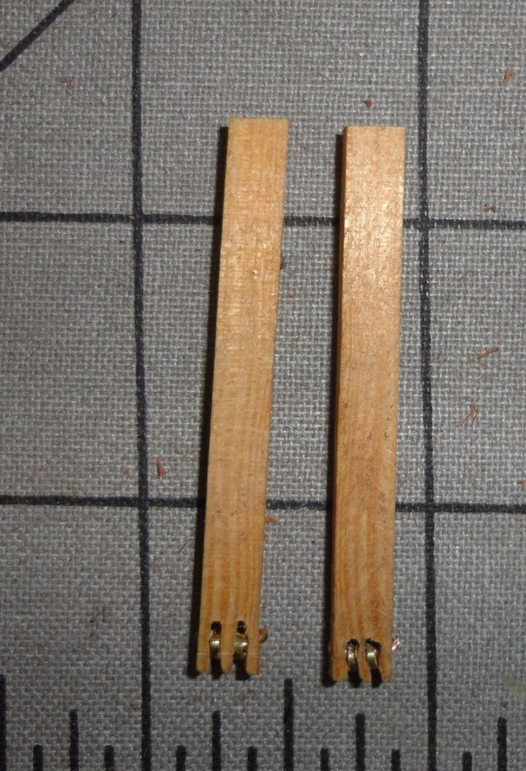
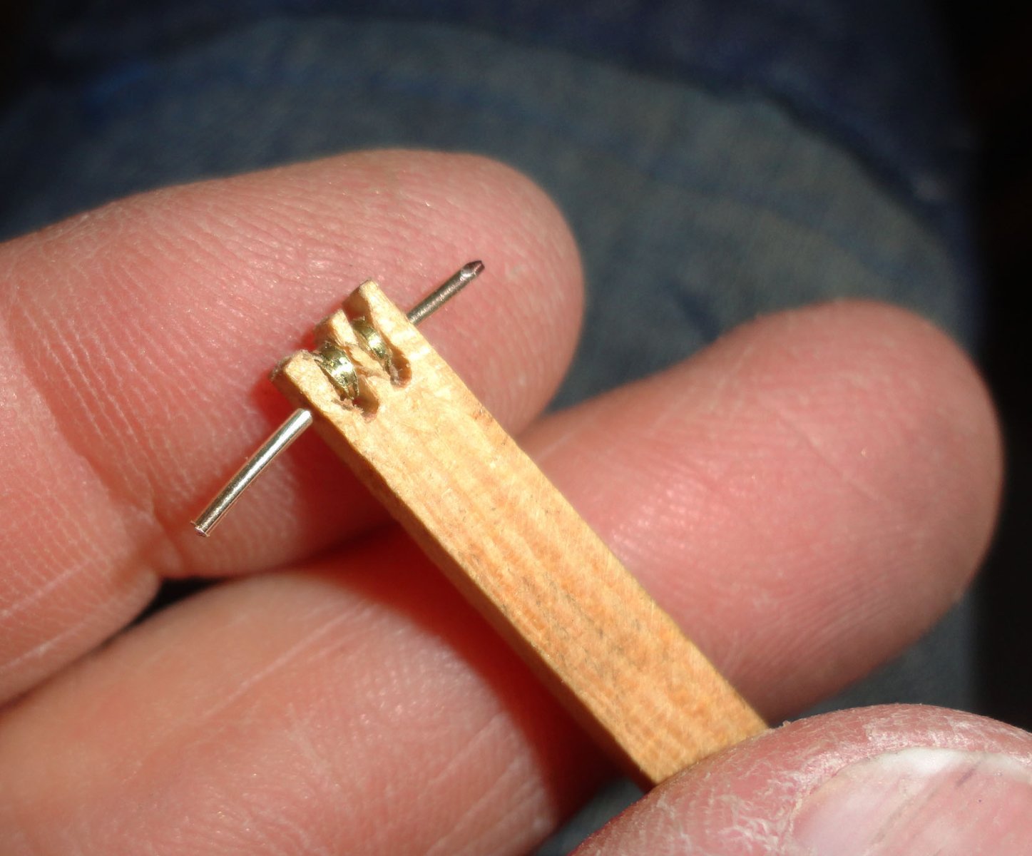
I'll need 2 catheads, so I found a piece of spruce stock from one of my 'parts kits', drilled a hole through the side for 20 gauge brass beading wire (soft state) with a finger operated pin vise, and cut two slots in the end for the sheaves with an ordinary hack saw (holding the stock end-up in a vise). A piece of 1/8" brass rod was chucked in the Unimat, and I drilled the same size hole in the end. I should have used a small center drill first, since the wire drill 'walked' a little off center before 'grabbing' ... no matter. A model railroad track saw was used to clice a thin sheave off the drilled stock after first scoring with a sharp pointed tool cranked-in from the side. The parts are shown below.
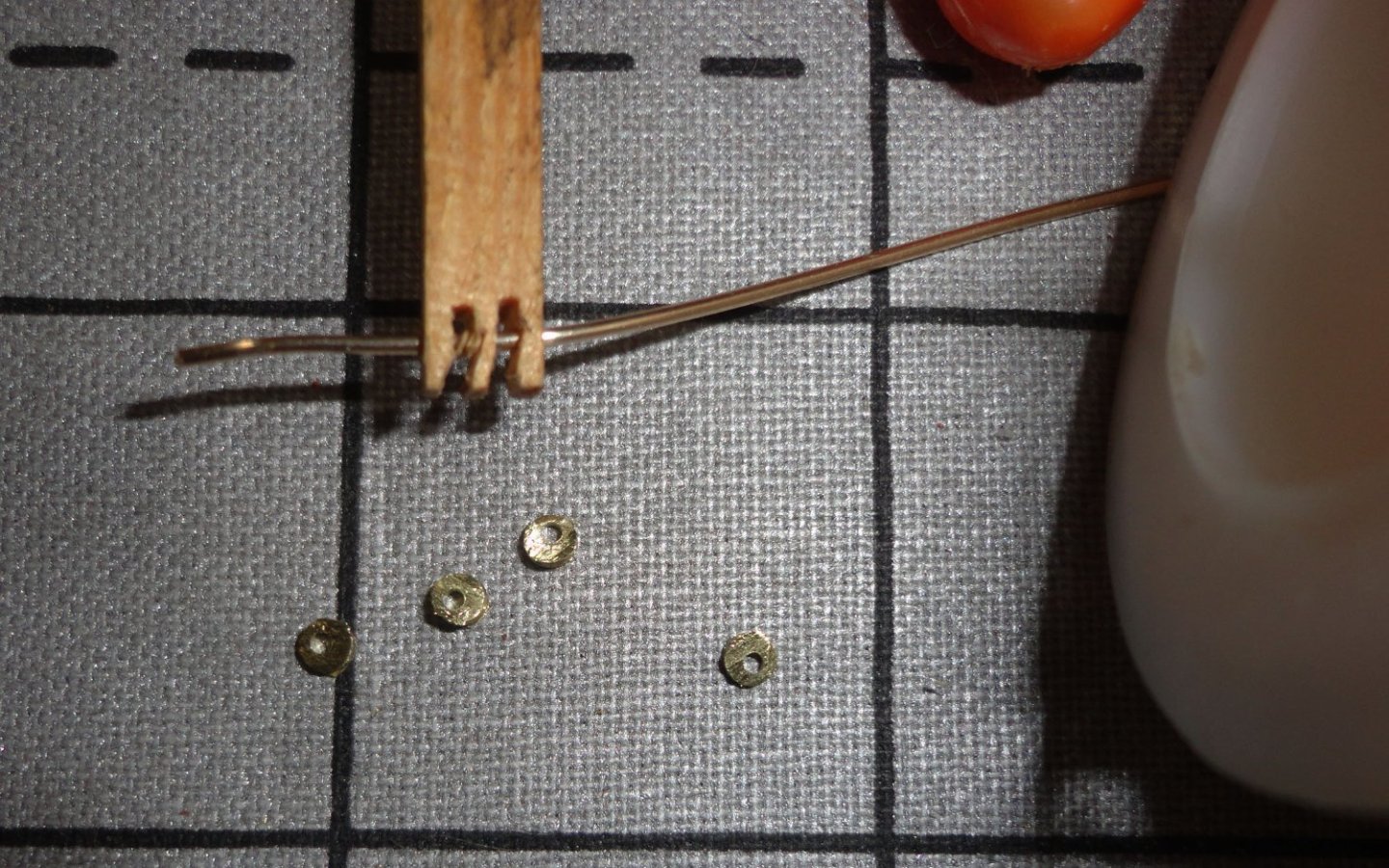
There was a little wobble to the end cuts in the wood - course corrected as I went. The second cat head came out better. getting the wire through everything was fiddly - a sewing pin was used to rough align the assembly, then the wire end was filed to 'sharpen' and it finally went through. One wire end was bent over a wee bit - the other cut with the angled side of the flush cutter so I could bend that bit over as well.

Below are the finished pair. NO, I'm not going to do the first one over ... its 'good enough' and the close-up magnifies every defect.
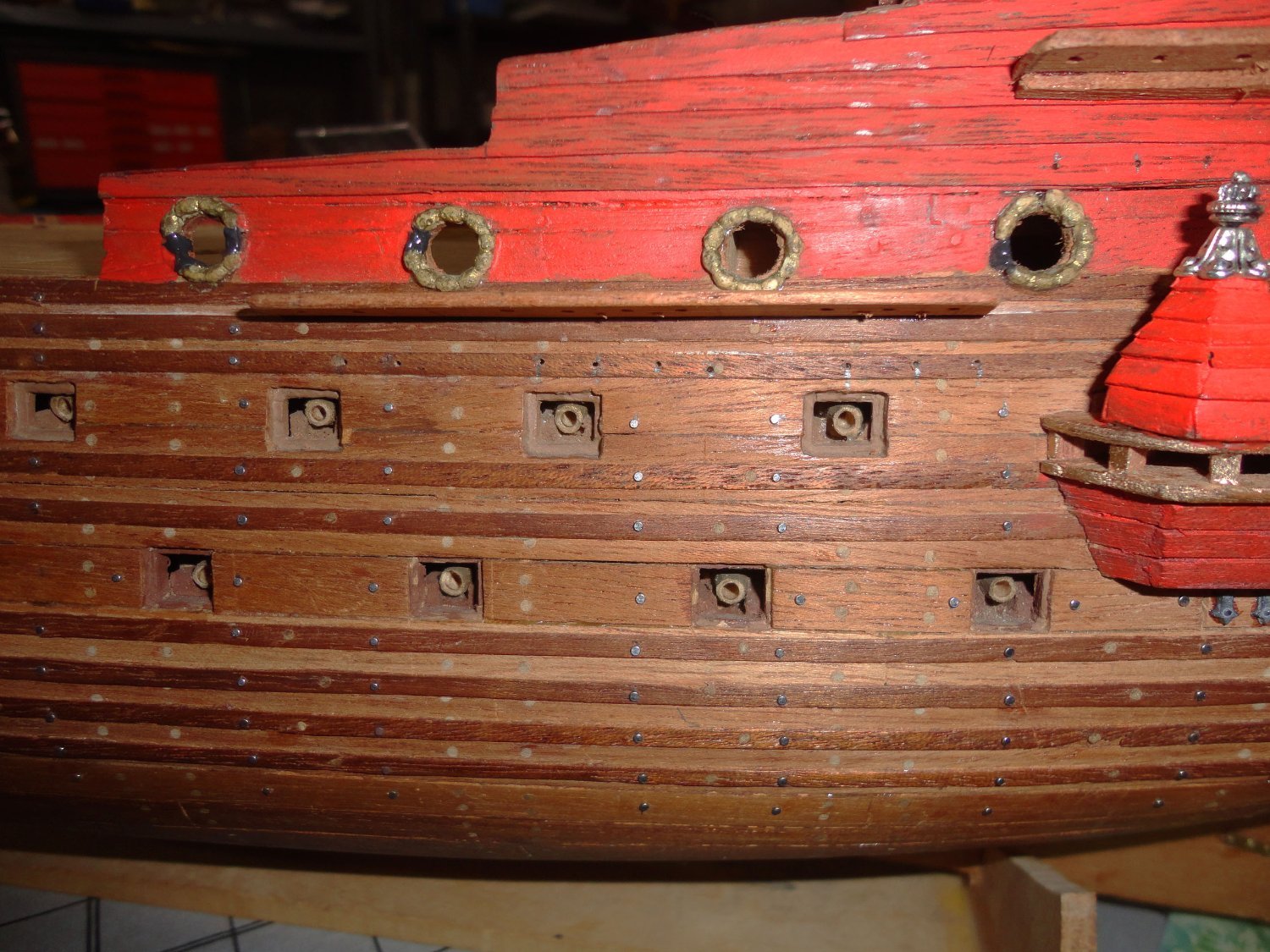
I did put the tiny brads in the sides and stern as previously indicated. Of the 560 that I started with, 130 remain .. so that works out to about 430 brads put into the hull ... I didn't bother counting as each hole locations was pencil marked, 'dinked' with a prick punch and drilled with the flex-shaft before each brad was positioned and pushed into place. I think they add something to the project.
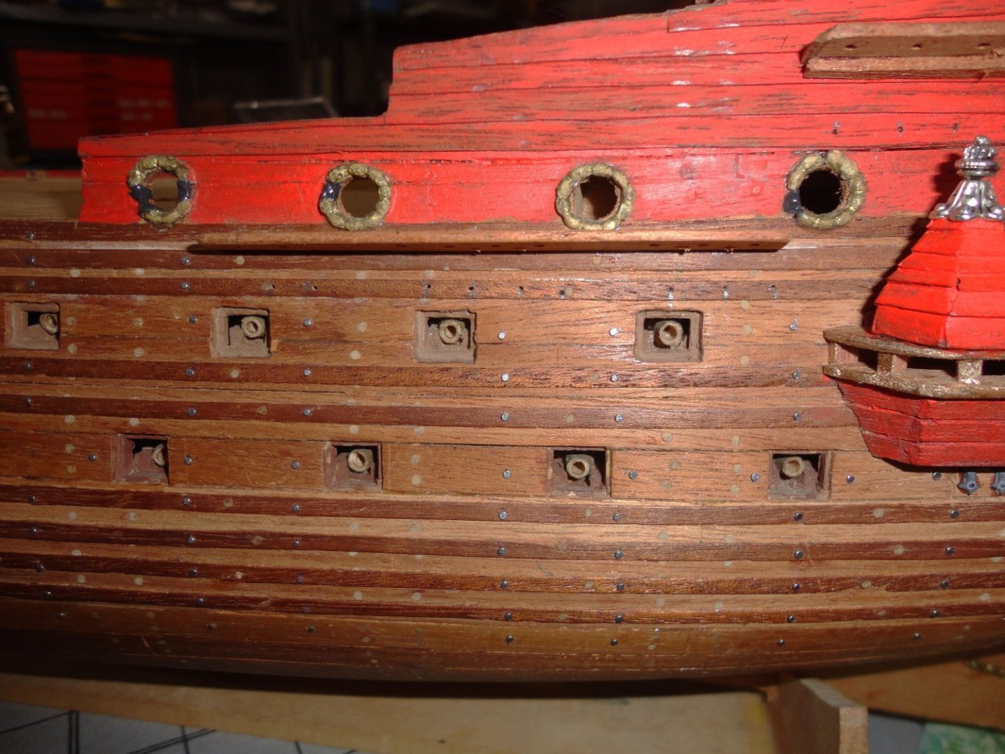
Too many brads might have been distracting as they are slightly out of scale (better for the 1:65 AL version), and the toothpick trunnels are also out of scale, so too many of them wouldn't have been good either. I find the combination pleasing, and I have only myself to please. BTW, the holes without brads in them are where chainplate will be fastened. The first mast sections were put temporarily in place so I could 'eyeball' (with a hacksaw blade as a straightedge) the line of the shrouds coming down to the lower deadeyes located by pre-drilled holes in the channel (can't be seen here) and through to the attachment point below the channel. Will it be 'exact'? Likely not, but not enough to be a bother - and that (as I've said) should be 'good enough'.
- Prowler901, Knocklouder, Ian_Grant and 1 other
-
4
-
I see you're in Alberta, and that make me recall a Gordon Lightfoot song, 'Alberta Bound' ... Anyway, GREAT JOB you've done on your project. I 'get' what you've said about not wanting a long dragged-out log, as there are others on this ship with a lot of detail. Still, I wouldn't mind seeing a closer picture of how you handled the stanchions and railing (there is a bunch) ... did you use the PE provided with rigging rope strung between, or did you go to the luxury of buying 3D stanchions for wire railing? This is a build in my future and I don't mind seeing how multiple builders did things on Endurance.
Come to think about it, ship modeling is really an art form, and what we make has to have at least some compromises from a full-sized version ... and the smaller the scale the more has to either be left out or simplified (like teeny ships in a bottle that require SERIOUS simplification). Another form of ship artwork is painting, so the farther away the ship appears in the painting the smaller the 'apparent' scale is - and the same 'simplification effect' applies to 2D art as it does for 3D art. So don't worry about close-up photography ... that only magnifies the smallest of irregularities that an in-person observer will never discern.
-
Super job, mate ! I'm seeing some advantages to modeling earlier ships ... no jackstays or footropes.
- Knocklouder, Keith Black and VitusBering
-
2
-
 1
1
-
10 hours ago, druxey said:
Another good composer to listen to while modeling is the prolific Musio Clementi. Hours and hours of early piano works.
Don't forget Georg Phillip Telemann - great baroque small-ensemble stuff.
- mtaylor, Keith Black and druxey
-
3
-
1 hour ago, allanyed said:
EXREMELY beautiful model! Like your carvings, the scratch built pinnace is something everyone should see and aspire to.
PLEASE do NOT take this as a criticism, but rather as a question only. Is there a reason you used Blomefield pattern guns instead of Armstrong pattern? Your title is 1765-1778 so the use of the Blomefield guns is confusing to me as they did not come into use until 1787 (Caruana, The History of English Sea Ordnance, Vol. II, page 257)
THANK YOU for sharing your build!
Allan
Hmmmm, 78 ... 87 ... could be lysdexia. (dyslexia 😉 )
- mtaylor, Steve Anderson and billocrates
-
2
-
 1
1
-
I have a an old Unimat miniature lathe. Since its powered by a Dremel type motor, it is underpowered for metal turning, but with light cuts it does OK on brass or aluminum stock (relatively small in diameter). Steel is tough on it, but wood cuts 'like butter'.
For our purposes, the most useful accessory is a 3-jaw 'Universal' chuck ... that is, one that operates with all three jaws closing simultaneously so that round stock is automatically 'centered'. One can then 'spot drill' the end on center (after facing-off the end), followed by drilling (sometimes in steps, depending on stock size). Since the Unimat is so small, the largest dowel stock that can pass through the head is around 1/4" - suitable for most yards and a good many mast sections - but not all, depending on scale.
You can see how I used my lathe in the Khufu build (see at the bottom of my post) doing a whole bunch of palm-head supports for the canopy.
A somewhat larger and more powerful lathe (that can also take thicker rods) would be preferable ... but only up to a point - we're doing modeling, not machine shop jobbing.
The second accessory to get is a 'live center' with drill chuck for the tail stock. This will permit support on the end of round stock so you can have a greater length extended from the head stock. This is limited by the diameter of the material (and the type of material), and the depth of cut - so that deflection is limited. What I've had to do is work on short extensions of stock (due to deflection and the lack of a live center), then advance the stock to work further down on the piece.
Drilling with the tail stock is done with an ordinary drill bit chuck that screws on the threaded portion of the tail stock - and is not 'live' (so the drill bit will not rotate).
Some time ago, a four-jaw 'independent' chuck was obtained for square and odd sized workpieces - and I was able to do round work by centering a piece of round stock 'reasonable well' (as large as 2" in diameter) within the steps of the jaws (when reversed), THEN truing-up the diameter by cutting the periphery after face-off. Boring was done with a small bar after drilling.
A "T" groove table mounted to the cross bar permitted a tool mount to be more easily manipulated and angled than an ordinary tool holder. These ideas should get you off to a good start.
-
1 hour ago, druxey said:
Wow! You certainly deserve a medal for persistence, Steven.
Some say that Domenico Scarlatti was the most prolific composer for the harpsichord, having written over 500 sonatas. Others say that he was the most PERSISTENT composer, having written a harpsichord sonata over 500 times. This may also apply to doing ratlines ...
- mtaylor, druxey, Glen McGuire and 1 other
-
4
-
OUTSTANDING method, mate ... and VERY well shown pictorially ! It is step-by-step and easy to understand what you did. This will definitely influence me on a future build, so I'll be sure to watch further developments on your build.
This is effectively 'caul bending' (or veneering), in which several thin pieces are formed around a bending caul (I may have the spelling wrong) after some glue is put between the elements to be formed. I did exactly this when building a bent-side Spinet Harpsichord (a large project). The side of the instrument's 'bent side' meant that I only needed a curved piece to bend against, and used a number of wood blocks held by clamps to keep the outside of the work-piece itself against the form (that had a small amount of 'spring back' allowance due to the 1/4" or 6.35mm thickness of the components).
You have made a nifty jig to allow the exterior clamps to hold the bent pieces together while the glue dries, due to the small size of your application. The thinness of your component pieces means that there is little need to worry about spring-back. The method you show may take planning and jig design, but it is WAY better than drafting outlines on plank stock, then jig sawing frames out.
Hand sawing frames makes for too much variation that is hard to sand to uniformity and still have them symmetrical. dealing with the grain of the wood can also be a challenge ... thin ribs are prone to breakage at the weak spots, and end-grain in places on the edges makes fairing and planking more difficult. By forming frames as demonstrated, there is great strength all along each rib. Once all the ribs are in place, a stable planking jig exists. Once planked, the attachment points along the sides are released and the ends can be trimmed where they should be.
Fair sailing ! Johnny
-
-
Thanks for the tip, George. 'Just ordered some in that size plus the next up from that ... they'll come in handy whenever the clipper project get underway. Right now, I'm focusing on finishing the current build - which has waited too long for completion. Yet the long delay has made current information and scholarship available, much to my advantage.
-
Perhaps some 'plastic wood' filler might 'fill-out' the bow area. Instead of the wood grate stock as railings, pins stanchions with thread (or very thin wire) may be better. Beads for dead eyes might do. Think 'out og the box'.


Plastic or Wood models? Your Favorite?
in Modeling tools and Workshop Equipment
Posted
Ahoy, Bill ! One advantage to wood is that one can re-do or re-shape things per one's whim. My Wasa (Vasa) build re-started with work I did decades ago on a planked hull kit issued well before all the original ship materials were recovered and restored as can be seen today - in person or on-line. I found that I could radically re-do things by just cutting into the wood and modifying ... (even more could have been done, but there are limits).
You have already skills far beyond beginner, and I can recommend kits from OcCre (available in the U.S. from several suppliers) that should prove more than satisfactory. The Endurance (some build logs can be viewed on MSW) seems a good value, and can be enhanced as some have done. If cannons are your thing, OcCre has kits for the Beagle and the Terror - two other 'ships of discovery' with storied pasts.
You won't need plastic glue, but 'Titebond' (or aliphatic resin carpenters' glue) will be a 'go-to' for wood-to-wood joining. Also PVC 'craft' glue can be used for some applications, and (of course) Cyanoacrylate (CA). I'm a fan of using medium gel CA and touching the spot I want to 'weld' with a dauber that was dipped in CA 'accelerator'.
I've used some plastic enamel (Testors), as well as acrylic flat paints.
Good Luck! Johnny