


Snug Harbor Johnny
-
Posts
1,383 -
Joined
-
Last visited
Content Type
Profiles
Forums
Gallery
Events
Posts posted by Snug Harbor Johnny
-
-
18 hours ago, VitusBering said:
Thank you Snug Harbor Johnny. I'll see how the strips look in my tests since they're almost here, but I think I agree that some sort of cylindrical thing - wire or plastic - might look better. I was, and sort of still am, a bit apprehensive about attaching a round thing atop a flat surface at that scale.
I also agree with you about the gap - yet they appear on several spars in the same places in both kits. An oversight? Maybe. At any rate, I can add them and probably will. Thank you very much for the info and advice.
Injection molds for all sorts of plastic products have 'ejector pins' that push the entire item out of a mold half with sprues still attached. Many times one can see various sized circular evidence on the plastic where these were located. I wonder if at those points on some yards there was an ejector pin.
I used to work in a factory where plastic hard hats, bump caps and welding helmets (among other plastic parts) were made. The molds can rather complex and the entire injection molder is a sophisticated device. The molds have to absorb the heat from molten plastic, and generally have a coolant running through them under pressure that is refrigerated by a 'chiller' and recirculated. When ejected from the mold, the plastic can still be warm - and if the production rate is set too fast, deformation can occur after the product has been removed if not carefully handled. This can be seen in some components of plastic models.
BTW, if you search 'Cutty Sark by Bruma' on our site, you can see a build of the 1:96 kit that is not too long - and not too far into the build there are very good photos of how he re-did the martingale in metal and did the chain rigging. The model (due to the way the mold was made) has a pair of rings for the chains facing sideways at the bottom (along the mold parting line), which can be satisfactorily used as-is. Note that the martingale and the whiskers projecting from the catheads are easily subject to breakage. Actually, dropping any model can ruin your day. Bruma showed how to reinforce the bowsprit when assembling.
- shipman, VitusBering and Cirdan
-
 3
3
-
Rob didn't use styrene for the jackstay, but a straight piece of wire laid across the small vertical projections - glued with a small dab of gel CA (applied with a pin ?) so it would cure (relatively fast compared to plastic glue) and resemble a real jackstay support once painted. He started at one end, and progressed going out from there. BTW, I rather think that there should be a vertical support in the "gap" you depicted.
-
A few posts up I mentioned making chainmail back in the day (while in College, between classes) - and I finally found an old picture of me wearing it prior to a mock Battle of Hastings re-enactment (the 'vest' of mail had not yet been fitted with sleeves, and would also be lengthened - and a fine mail coif was later fashioned - all eventually sold). That time I portrayed a Saxon archer with long bow (there were some at the battle). My arrows were blunt and padded, and only fired (after notice of a volley was given) when the Normans raised their shields.
The melee weapons were a plywood axe and a strap iron short sword with wooden handle & cross guard. The helmet frame was bent aluminum, still awaiting metal quadrants to be formed and riveted in place. Saxons lost ... as usual, but I did not flee the field so died a brave 'death'. That evening, the victors and the raised dead all feasted in a Church hall - eating roast meat and lentils served on bread 'trenchers' and home-brewed 'short mead' quaffed from cow horns or grails ... a beer-like fermented concoction of honey, water plus wine yeast allowed to work a few days in a plastic garbage can. Like in Valhalla, songs were sung and tales were told, and there was some fine wenching as I recall.

-
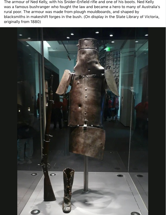
G'Day, mate ! Thought you might know about the famous (infamous?) Aussie referred to in the picture below.
- Glen McGuire, Keith Black, mtaylor and 1 other
-
4
-
I love the scale of your deck planking !
-
-
'Gosh - I forgot about how I used to make rings for chain mail ... That was to wrap coat hanger wire around a 1'2" rod to make a coil, then cut off links with aviation snips. Yeah, the ends weren't flush - but a couple passes with a file would smooth things. Now TINY rings are another matter, but using small 'flush cutters' on brass wire would leave one side nearly flat. But if the best flatness is desired, the sawing method sounds like a plan.
There are fine saws for cutting 'tubular' (or other) metal model train tracks that are rigidly backed.
-
Aside from split rings for jewelry/beadwork sold in craft stores such as Hobby Lobby or JoAnns - there are also specialty stores FOR these crafts. Still, there are limits as how small JUST split rings are made. BUT, there are VERY fine chains sold that are made up of ... rings that can be disassembled (as they are split). So find chain having circular links the size you want, and use 2 very fine needle nosed pliers to separate the links. You'll likely nee a head held magnifier and steady hands - but then those are needed for a lot of the work we do.
-
Before using a center punch on any piece of metal, a 'prick punch' is lightly tapped to get a very small dink where layout marks or scratched indicate. A prick punch looks much like a center punch, except that the angle of the tip is much more 'pointy' than the angle of a center punch - which corresponds to the standard angle for drill flutes. The end of a piece of drill rod (or a shank broken off a drill) can be ground (dipping the end frequently in water to avoid losing the hardness) to a sharp point, then it would be a miniature prick punch that might be safe to use on the item in the photograph.
If the concern is that the fragility of your work piece won't hold up against any sort of impact, you might slip the brass ring off the yard and support the ring with a brass rod that just fits through the ring. Then a prick punch would be safer - and a 0.6mm drill will 'bite' without needing further punching.
If ring removal is inconvenient, then a thicker (relatively) metal collar that has already been crossed drilled and just fits over the brass ring you want to drill through will act as a 'drill bushing' to guide the drill - no punching is needed in that case. For multiple sizes of brass rings, multiple bushings would have to be made.
- Scotty W, CPDDET, Roger Pellett and 2 others
-
5
-
2 hours ago, Glen McGuire said:
Any pictures?
Alas, no. But my brother said I could have it back the next time I travel to visit ... and he'd also have to find which box he packed it away in - what with two estates (my parents - but not at the same time) he was the executor for.
- Keith Black, Glen McGuire and mtaylor
-
 3
3
-
I've always learned from mistakes and also by observing others. I used to watch my dad build RC aircraft the old 'stick built' way - and after a while he built me a small work bench to try and put what I observed to use on a rubber powered plane. 'Seems whether wooden airplane or boat, learning to cut with either X-Acto or saw is essential - as is pinning, gluing and using files or sandpaper. Finishes/painting is yet another area to experiment with.
Learning how much one can bend various thicknesses of different woods without breaking comes in handy - as well as effective use of soaking. But that knack wasn't acquired until I broke a few pieces, or over-soaked wood for wet bending. And 'thinking through' how something has to go together can allow one to get by with less reliance on instruction sheets. Only by doing things in note the best order imparted the insight of how to do better next time. As mistakes were made, I learned likely remedial actions/reworking as needed. The results were not always 'pretty', but the journey of learning was engaging.
So I'd say that for most anyone past their teens, one 'middle sized' intermediate ship kit can be enough to tackle something big - perhaps even a 'dream ship' ... for that journey will likely take a couple-three years or so (depending on life's demands).
I remember one day when I was servicing my Schwinn bicycle - you know, the old-school 'one speed' kind (three-speed on the handlebar was for girls). I'd taken the rear wheel off to free the chain for cleaning and re-oiling, then I had to replace the wheel and tighten the nut onto the central bolt. But how 'tight' is tight supposed to be? I kept tightening, noting how much force it took ... then tightening some more ... then it was much harder to get it any tighter until ... it suddenly got looser!
What just happened, I thought, as I took the nut right off in my hand. The threads inside the nut were 'stripped', as the manufacturer wisely designed the shaft's external threads to be harder than that of standard nuts for 3/8 UNC. That way, the NUT would be the thing to fail - which is much easier to replace than the wheel axil bolt. EPIPHANY, it truly was, so I went through my dad's jar of spare nuts and bolts to find one that would suit. Then I tightened the replacement - remembering the force it took to get the nut tight, but NOT so much as to strip the replacement. From that happy afternoon, I was 'calibrated' as to just how much to tighten common sized fasteners without stripping the threads ... and since then it hasn't happened again.
That's how one learns, and not letting failure dampen enthusiasm - but rather letting it point to wiser ways going forward.
- Knocklouder, Ryland Craze, Canute and 2 others
-
4
-
 1
1
-
33 minutes ago, Louie da fly said:
After watching your video I've decided I'm NEVER going to build a ship in a bottle! It was actually painful to watch - I was sure it was going to be a disaster. I takes me hat off to you sir!

PS: Bundy is rum, not beer. A suitable drink for a shipbuilder, I feel.
Steven
Steven, I did one ship in a bottle some years ago. Perhaps once is enough. One of my brothers currently has the bottle.
-
Very nice work on Polaris !
- Ryland Craze, Mr Whippy and ibozev
-
3
-
I forgot about Durham's water putty (which cures fairly tough - perhaps not quite as hard as what Dentists call 'stone, a type of plaster made for casting likeness of teeth after and impression is made), and can be sanded. You need to apply to a 'porous or fibrous substrate (like coarse sanded planking) ... something with "tooth" for the plaster to grip to. If one seals first (or the surface is very fine sanded), the dried Durham's can flake off. No fumes to worry about, mate. Yet manufacturers are advised by their lawyers to be SUPER cautious and plaster warnings all over whatever product they are selling. Like a flimsy card table that has a warning - DO NOT stand on this flimsy POS - because it will collapse under your weight.
-
Back in the day, there used to be a pretty good wood filler known as Hobbypoxy Stuff. It came in a can pre-mixed and ready to use, and it air dried without (as I remember) much of a smell - and could be sanded once dry (depending on the thickness applied). Of course, that was back in the day of small hobby shops selling supplies for stick-built model airplanes (RC or not) - plus trains, plastic models, etc. I've no idea if 'Stuff' is still available, or whether there is an alternate product.
- mtaylor, DonBMichigan and John Ruy
-
3
-
-
48 minutes ago, VTHokiEE said:
Thanks for the tip - I’ll have to give it a try. These were used books and none are valuable antiques. Should I worry about the spots on the (what I assume is) linen or textile covers?
I'd leave textile spots alone. Trying a 'spot remover' might only make them worse.
- shipman, mtaylor, thibaultron and 3 others
-
6
-
'Left my car windows open and an unexpected thunderstorm got water inside. The seats dried OK the next day (which was sunny) but water soaked seep into the floor carpet and a musty smell was quickly generated. Even after several sunny summer days had likely allowed the water too evaporate, the musty smell lingered. What I did was to use a whole box of baking soda sprinkled all over the floor carpet and 'worked it in' a bit. Then after a day I vacuumed the powder away, and the smell was greatly reduced. So I repeated the treatment and the smell then was mostly gone - then after a month it was completely gone. I don't leave my car windows open anymore ... since water is the real culprit that allows mildew to proliferate.
Sooooooo, this is why the second solution pasted below holds promise. I used to know a librarian that had knowledge of paper conservation methods, and she said acids in the paper greatly contribute to premature yellowing (aging) and weakening of wood pulp paper. VERY old books (pre 20th century) are more likely to have paper made from rags (cotton fiber), which last a lot longer. I imaging that sprinkling a little fine baking soda BETWEEN the pages can also be effective in odor removal (just a couple days in a sealed container), before fanning the pages to let the powder fall out.
Fresh Air
Very light cases of musty pages can be cured with a little exposure to fresh air. If the book is not a valuable antique, you also can treat it with a few hours of direct sunlight. However, before you begin this or any other book-cleaning method, it is essential to make sure the pages of the book are not damp. If you see wet or damp pages clumping together, stand the book upright on a table, and gently fan out the pages to separate them. Next, let it stand in a warm, dry spot. If the book is very old or valuable, do not place it sunlight. It may fade pages and cause them to permanently curl up.
Baking Soda
The same baking soda that absorbs bad odors in the fridge can absorb the bad odors in your books. Place a cup of baking soda or an opened box in a plastic box or bin with a lid. Put the book in the box with the baking soda and close the lid. Leave it for 48-72 hours, then check on the book. Repeat until the odor is gone. This method is ideal for multiple books.
- mtaylor, thibaultron, Ryland Craze and 3 others
-
5
-
1
-
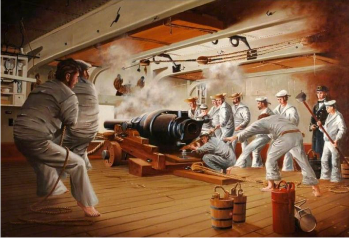
Crew of a 110 pounder Armstrong Gun, firing, aboard HMS Warrior. The Rifled Breech Loading guns made by Sir Armstrong's orginal system of construction was adopted in 1859. Although manufacture was discontinued in 1864 they continued to be used for many years due to the numbers produced.The Armstrong RBL 7-inch gun, also known as the 110-pounder, was an early attempt to use William Armstrong's new and innovative rifled breechloading mechanism for heavy rifled guns.he Armstrong "screw" breech mechanism used a heavy block inserted in a vertical slot in the barrel behind the chamber, with a large hollow screw behind it which was manually screwed tight against the block after loading. A metal cup on the front of the block, together with the pressure of the screw behind it, provided "obturation" and sealed the breech to prevent escape of gasses rearward on firing. The sliding-block was known as the "vent-piece", as the vent tube was inserted through it to fire the gun. In modern terms it was a vertical sliding-block.To load the gun, the vent-piece was raised, the shell was inserted through the hollow screw and rammed home into the bore, and the powder cartridge was likewise inserted through the screw into the chamber. The vent-piece was lowered, the screw was tightened, a tube was inserted in the top of the vent-piece, and the gun was fired.Shells had a thin lead coating which made them fractionally larger than the gun's bore, and which engaged with the gun's rifling grooves to impart spin to the shell. This spin, together with the elimination of windage as a result of the tight fit, enabled the gun to achieve greater range and accuracy than existing smoothbore muzzle-loaders with a smaller powder charge.On top of each powder cartridge was a "lubricator" consisting of tallow and linseed oil between two tin plates, backed by a felt wad coated with beeswax and finally by millboard. The lubricator followed the shell down the bore, the lubricant was squeezed out between the tin plates and the wad behind it cleaned out any lead deposits left from the shell coating, leaving the bore clean for the next round.
-
Since I'm on-and-off the site at irregular intervals, I miss a lot of stuff ... dang, 'just remembered there is a place to click to see posts 'since the last visit'. I keep forgetting about that. You know, they say the memory is the second thing to go. What was the first? ... I forgot.
Yet the GH is a definite interest of mine, and I have a Mamoli kit in my stash that I want to "bust" based on all the research available since the 80s kit was made - I inherited it from my father, and I'm amazed at the number and quality of the drawing provided, also an 'old school' feature in these days of more limited photo instructions and few full sized plans. The Revels kit is an old standby, and you're putting much care in the build.
Thanks for your clear photos and posts! Johnny
-
As a teen, I made a dandy model of the liner United States out of paper that was about 2 1/2 feet long. With everything I made in those years, there is no notion what happened to it (other than a parent 'cleaning house' while I was away). I went to a dock on the Philadelphia waterfront some years ago to see the once-proud liner moored, neglected and showing rust. 'Guess with everything already stripped from her - as well as all the asbestos still inside - it turned out to be cost prohibitive to get her ship-shape to cruise again. People game for cruising prefer those mega 'love boats' afloat these days.
-
'Looks to me like thin copper sheet is just applied over an underlying row so it "looks" like the plate below is tapered. In the case of planks (which are much thicker, the 'stealer' is tapered down to nothing (in a planned way) and the next plank butts up against it and then onwards - and the new plank may be tapered also as needed.
But remember the 7th Commandment 'Thou shalt not steal' ... (so why would the Lord help them who 'help themselves'?) And there are logs/references elsewhere in MSW that demonstrate how (with a bit of planning and foresight ... and a lot of pre-marking the bulkheads - or first layer of planking in a double planked model) one can completely plank a curved hull without having to resort to stealers (except perhaps in the stern where the fairing must go out to a vertical (or near vertical) profile where the rudder will attach.
Briefly (as I recall), one makes even marks (equal to the widest planking stock) up and down at the widest point of the hull - that where the distance from the shear to the keel is longest. Then one makes the same spaces pencil marks along a straight line equal to the distance marked on the hull on the short side of a piece of paper. Turn the paper sideways and mark the center at the opposite end. Using a straightedge, draw lines from each (numbered) pencil mark all the way to the 'vanishing point'. Now you have proportionally decreasing lines.
Measure the length from the shear to the keel at convenient distances fore-and-aft, and cut a vertical slice from your proportional drawing where the distance from top to bottom matches the new distance measured on the hull. Use the marks on the guide to transfer mark to the hull (doing do both port and starboard). When done (and it is a little tedious), you will have the entire hull marked out (save as noted at the sternmost area - there you will have to have a couple inserted pieces).
Each plank will have to be custom tapered (and with a slight bevel on the edges as needed), as measured off the pre-marked hull. This step is even more tedious than the marking, but that is what 'museum quality' models exhibit.
Now for a ship to be copper (or Muntz-metal) bottomed, you can forget most of the above and plank below the waterline any way you want as long as you're happy with the lines - that area will not show. Another technique I've seen on some models not copper clad is to stop planking a little below the waterline and have enough ribs showing (one can cut out the bottom center area of solid bulkheads so that what will show will resemble ribs) and add enough 'dummy' ribs for good measure (they can be fit in after planking). Then you don't have to plank the entire hull OR go to the trouble of coppering - and still have a dandy looking model by doing a good job of everything else. Many British Admiralty models were made in this manner.
-
Vlad, Your pictures of the lower topsail yard with Howe's rig are the clearest yet on how that can be done. The pair of eyes on top of the yard through which the bar of the gantry passes allows for some dimensional chance of the triangle formed by the gantry and crane below as the yard swings to either side. The weight of the yard is shared by the gantry and the crane together. The crane has a pivot beneath the yard, and the foot of the crane is an eye resting on (and passing through) a fixed eye at the mast - so the crane can swivel right or left, with the yard moving slightly forward or back along the bar of the gantry as the geometry dictates (due to the pivot point of the crane being closer to the mast than the pivot of the gantry above at the level of the yard).
Done this way, the forward thrust generated by the upper and lower top sails when both are set (the lower edge of the upper top sail being laced to the jackstay of the lower topsail yard as you describe) is split between the upper topsail yard (conventionally rigged with a bracket that can slide up and down the top mast) and the crane that connects the yard to the mast (the gantry as shown does not have an end stop, so cannot transmit thrust to the mast). Of course, there are braces for both yards that can also transmit thrust to the vessel when belayed and the lines are tight.
Now if the beam of wood placed on of the bottom front portion of the topmast (to which the fixed eye for the crane's bottom eye is mounted) was not tapered, but was of a thickness to match the location of the gantry pivot on the cap where the yard is mounted, then the triangle formed would have no dimensional shift as it turns ... imagine a 'solid' triangle of metal hinged to the mast (with a suitable piece of added wood to the base of the topmast that is even with the cap above) that can swing freely to either side. It does not change its shape. I suppose that an iron bracket or ring with a protrusion could attach to the mast at any position (per the length of the crane), so that the fixed eye will be directly under the pivot of the gantry above it - thus no need for the added wood. If the crane is a longer one, it could go all the way down to the forward edge of the platform platform to an eye that would be in-line with the gantry pivot above.
Then there would be a bolt or suitable end stop at the end of the gantry arm so that forward thrust can be transmitted. As the yard bears against the stop, force would go through the gantry arm to the mast cap. Then only one eye would be needed on top of the yard as there is no forward and back motion. This would also be advantageous if only the lower topsail were set (e.g. when the upper topsail yard was quickly lowered as a squall approached).
I'm still in the learning phase, and seeing all your wonderful pictures is highly instructive - as are all the fine build available on the MSW forum!
-
8 hours ago, mikegr said:
This is a test performed at almost 0 distance and 0 angle.
In a real situation, say 30k+ yards at an impact of 40+ degrees the result would be far different from the one shown above
http://www.navweaps.com/index_tech/tech-040.php
As usual when all the data is examined, a more realistic picture can be envisioned. Still, hits on lighter armor would likely have some effect. 'Brings to mind a visit I had in the 1970s to the outdoor WWII Tank collection at the Aberdeen Proving Grounds in Maryland. There was an example of a Jagt Tiger (Hunting Tiger ... or was it a Jagt Panzer) non-turreted anti-tank vehicle with thick, sloping front armor. There had been a direct hit from some allied gun on the front, and it looked as if an oversized 'ice-cream scoop' had taken a 'scoop' right out of the armor plate (something like 6" thick) ... but the round did NOT penetrate. Another round had been deflected by the gun mantle. It would have taken another hit in exactly the same spot (not likely) to have a chance of defeating the armor in that location.
Some of the tanks had open hatches so a visitor could get inside (which I did). There was also an indoor museum of all sorts of military items, but I don't know if anything seen decades ago has been maintained or is available for viewing these days. One would have to check before attempting a visit.


HMS Beagle by Capella - OcCre - 2nd build
in - Kit build logs for subjects built from 1801 - 1850
Posted
A wooden filler block of basswood (or even balsa) in the space between the last frame (bulkhead) and the keel astern that is faired would go a long way to preventing an 'acute' angle the plank wants to make over the last frame when there is nothing else to support it over the last gap where the curve is considerable. Some go so far as to put filler blocks in all the gaps - but having them in the last couple of gaps fore and aft can be sufficient. Wetting and heating the plank more in that area (plus a little 'pre bending') will make it behave better when applying to the hull. You are not so far along that you can't put in end blocks, even if it means taking off a plank or two before proceeding.