HOLIDAY DONATION DRIVE - SUPPORT MSW - DO YOUR PART TO KEEP THIS GREAT FORUM GOING! (Only 36 donations so far out of 49,000 members - C'mon guys!)
×


Snug Harbor Johnny
-
Posts
1,466 -
Joined
-
Last visited
Content Type
Profiles
Forums
Gallery
Events
Everything posted by Snug Harbor Johnny
-
 The stowed position lifeboat photos are very helpful. It appears that the 'ratlines' are solid bars fixed between the center pair of wire-rope shrouds. I note additional funnel detail, the whistle and various lines attached to things. 'Looks like there are u-shaped rowlocks on the lifeboat. The first photo shows a small platform in a 'lowered' position (notice the longer length of the ropes between the double blocks used to raise or lower the platform), and the second photo show a higher position, also judging the new downward angle of the safety rope going through the stanchion eyes. 'Would be nice if there were more pictures to better show how that rig worked. Note also that the portholes in the aft cabin are simply round holes in the wood with no eyelets (as provided by OcCre) or any external fittings. Ergo the porthole glass was mounted internally and opened inwardly. Too many details to process now. Johnny
 -
Ach so ... Ausgezeichnet !! Something useful for most any late clipper (and earlier). On small models I used to tie a stay and then continue it, but on large enough models something that looks like a bee or sheave is in order. I too have much to learn. BTW, the 'Glory' postings have been of great interest to many and are definitely among the 'hot' topics on the forum. Bravo!
- 3,560 replies
-
- 1
-

-
- clipper
- hull model
- (and 2 more)
-
Your images show a couple interesting aspects concerning the life boats and their placement. (The names of three of the life boat and their dimensions are noted in my posting to the 'review' of the OcCre Endurance kit.) On the starboard side, the small transomed lifeboat is forward, and one of the double-ended lifeboats in astern. On the port side, the large transomed lifeboat is astern and other photos show the second double ended lifeboat (likely the David Cairn used by Shackleton for his rescue effort - since they took it down in the photo) carried forward. One could really do these small craft justice by modifying them to conform to the known dimensions ('busting' them as 'mini-kits'). They had a slight upwards curve toward bow and stern - easily achievable by fixing the strake under the gunwale first with this curve, then planking downward to the keel. The gunwales would appear more to scale if they were thinner (using the kit supplied gunwale as a template over thinner stock of better wood), and they would bend to the curve fore and aft easier and glued into place. I plan to equip mine with oars, unstepped mast(s) as applicable, rolled sail(s), rope and other supplies they likely had. As seen on other builds, the ribs above the footlings can be replaced by more and thinner internal ribs. Shackleton's boat was well photographed and now on display in a museum. I note that it received extensive modifications by the crew before they set out on the hazardous sea voyage, and many of those are photo-documented. Ergo the two same-sized double-ended life boats should appear as they did before being stranded in the ice. The two transomed crafts served as vital winter huts for most of the crew. The most important and effective enhancement to the OcCre kit (in my opinion) is with the railings. I've obtained correct sized 3-D (turned by miniature automatic Swiss lathe) stanchions from Cornwall models - including the ones forward having a hole for the single rail, and the far more numerous twin-rail stanchions. The are bulbous where the rails pass through, and have cylindrical bases to better mount them on the gunwales/deck edging. I'll have to make a scale plan view marking each location, then determine the exact spacing needed for discrete 'runs' of railing. Then these distances will be drilled in a straight line on a wooden holding jig, railing passed through entirely straight - then each joint will be soldered with a mini propane torch and thin circuit board resin core solder. I've worked in this medium before and as long as not too much heat is used the joining will come out very well. Then each 'run' of railing will be formed either with bends or gentle curves as needed to conform to the plan view. The formed rails will have the very bottom of the stanchions daubed with gunsmith's inletting black so an exact series of 'dots' will be transferred to a piece of wood to serve as a drill jig (drilled through on a drill press to insure perpendicularity). The jig will exactly fit over the required area of the model, then the pilot holes (slightly smaller the the stanchion ends) will be hand drilled into the model squarely. I'll remove any remaining inletting black from the railing runs, degrease then paint the railings white. They can likely be assembled on the model snugly enough without glue, or a tiny amount of slow setting glue can be pre-inserted into the pilot holes with a fine probe prior to final assembly of the railings. The railings were a distinctive feature of the Endurance (as they were also on the Aurora, the 'sister ship' to the Endurance that headed to the opposite side of Antartica to pick-up the team that was suppose to traverse the continent). Enhancing this feature will greatly improve the model. Dogs were a key part of the venture (they finally learned this from Amundsen - first to reach the Pole), and special dog runs were constructed on the Endurance that all have to receive railings on either side. Indeed, the dogs insured the survival of the crew ... just not in the way anticipated. Smooth sailing ... Johnny
-
'Just love your fairing technique ... running stringers at different angles and taking the 'long view', since the eye can see any 'wobble' in the line. I'm learning all sorts of techniques and tips from different builds so when I get into the next ship I can do a better job of it. Slatki kak sacha. Spasiba ! ... Johnny
-
Steven, your build log is a tonic since I think back to my 14 year old self trying to tackle the first edition of the Billings Wasa in 1:100 ... The solutions you show are instructive, as well as many ideas and techniques seen in other builds. I'm likely to incorporate many forum methods over the winter in what will be the best 'compromise' build of my dusted-off project - pictured in a log I started after finding MSW. I'm happy to consider this sort of work as an art form one learns as one goes. Fair weather ! Johnny
- 740 replies
-
- 4
-
-
- Tudor
- restoration
- (and 4 more)
-
'Just love the boat - the thought you put into it shows.
-
Now I can see how the planking was done ... so whatever goes inside rib-wise or thwart-wise is an installation process - plus whatever else in the way of oars, mast, rigging, etc. Very nice! I'd like to 'improve' (bust?) the ship's boats of the Endurance (actually I'll build them first as practice), since we have exact measurements on three of them (the fourth was the same as Schakleton's lifeboat) and many photographs. There was a recent post on improving ship's boats for HMS Victory, where the assembly ribs were removed and replaced by more scale-like boat ribs - along with thin footlings, scale gunwale (with grain going in the right direction) and a variety of accouterments on hand in such boats. Each boat also has a graceful upward curve to the stem and stern (not sure of the correct term) - and that might be done best by installing the plank below the gunwale first to establish the curve - them go on planking downward (tapering planks as needed). Taking the time to do a better job on details such as these will greatly add to the appearance of the model as a whole. Johnny
- 83 replies
-
- 1
-
-
- Sea of Galilee boat
- SE Miller
- (and 1 more)
-
I read an article on the 'Jesus boat' recovered in Galiliee ... is this the same boat as the one in this thread? The boat in the article in Biblical Archeology Review showed the the strakes were composed of many oddly shaped planks (some of them short) that were fastened together with lashings passed through severely made holes in the plank edges where they abut. The whole thing looked like a big 'jigsaw puzzle'. The article suggested that valuable wood resourced back them was used with a minimum of waste ... it reminded me of some Inca stonework where all the oddly shaped blocks were fit together so as to remove a minimum amount of material, yet be snug against each other. Johnny
-
I've learned that epoxy, like CA, goes bad after a while on the shelf - especially at room temperature. It's a good idea to buy new epoxy for a given build, and store epoxy (and CA) in the freezer (in a ziplock bag). Date the bag and still discard after 1 year (a rule of thumb).
-
I've found that old kits - sometimes incomplete/damaged or partially built can be found in flea markets or garage sales at a bargain price. These can be good sources of wood, parts and supplies useful to enhance current builds or to scratch build. Some old kits have good planking for those who don't want to do a lot of sawing (very dusty) or buy new stock by mail. Other items may not be as useful, so its sort of a 'grab bag'.
-
Gosh, I'd not heard the term settee (sail) before, so I Googled it and Wikipedia 'characterized' it (with illustration) as a lateen-like sail with the 'front corner cut off' to make a quadrilateral sail. hen I looked at the tombstone in question again and can plainly see that the front (downward) end of the sail exhibits this quadrilateral form - that is, there is a short vertical edge of sail below the end of the yard ! By George, you've got it ! (say I). The 2nd century tombstone sure seems to depict the settee sail design - the same one shown in the 5th century mosaic (and Wikipedia). The earlier work is a pretty good work piece of art rendered in perspective (note the difference in the sizes of the figures and the receding prow of the boat). This suggests that the settee came first (whose basis is a modified square sail), and the lateen evolved from that. How cool is that? Johnny
- 83 replies
-
- 4
-
-
- Sea of Galilee boat
- SE Miller
- (and 1 more)
-
Of course, the tombstone image may be an artistic device to 'fit' the sail into the space limitations on the piece. A square sail wouldn't fit if the yard was perpendicular to the mast in this apparently unique example. Opinions will vary, and the way the lateen was 'invented' may have been by tipping the yard down toward the bow while bundling the corner of a square sail at the for end of said yard.
- 83 replies
-
- 3
-
-
- Sea of Galilee boat
- SE Miller
- (and 1 more)
-
Your process for removing the bulky kit 'frames' after planking, then replacing them with appropriate wood strips vastly improves the ship's boats ... something that I have been pondering with the OcCre Endurance kit I have yet to build. It has four boats also - two double-ended life boats that (from photos) are apparently of the same design (the James Caird used by Shackleton survives and is on display in England), and two others with different dimensions and transoms (measurements and photos are available, but theses boats did not survive). If the kit is built 'out of the box' per instructions, the results are good enough at the intermediate level, but I'd like to go the extra mile and modify wherever practical to get closer to the original ship and its equipment. Your 'tutorial' will greatly help me when I tackle the project (however, I'm waiting to see how a couple of forum builds turn-out on this new kit - learning in the process). After doing better ribs, I'll make a more appropriate gunwales, and equip the boats with stowed oars, mast(s) and sail(s), rudder gear (where applicable) rope and supplies. Thanks mate! Johnny
-
kit review ENDURANCE by OcCre - 1/70 scale
Snug Harbor Johnny replied to ccoyle's topic in REVIEWS: Model kits
That's first class work, Keith - and a great option for stanchions with railing! -
kit review ENDURANCE by OcCre - 1/70 scale
Snug Harbor Johnny replied to ccoyle's topic in REVIEWS: Model kits
I overlooked an important feature of the new kit ... the etched (or lasered) brass stanchions for the railings. They happen to be pretty flat, while the originals were cylindrical with bulged joints where the horizontals went through. I found some suitable 3-D brass stanchions in the component market on line, but the the cost with shipping (about 80 double-rail verticals, and about 16 with one rail) would exceed $100 - more than 1/2 the kit cost ... some upgrade. If cost is no object, then OK - so let's look at the provided stanchions more closely. Below a flare at the base of the flat upright, there is a 'spike' to go into the wood of the model. (Obviously a cylindrical sub-base would be much better.) To prevent a tendency to 'wobble', a fillet of glue (epoxy?) on either side of the stanchion would be needed to secure the flat ones with the kit. The 'out of the box' construction uses rigging rope as the horizontals, so care is needed not to stress the stanchions while 'rigging' with rope ... but then then the original ship had metal guard rails (everything painted white). Trying to 'thread' wire will be difficult indeed. If one purchased 3-D uprights, then the best way for every 'run' of railing would be to determine the exact spacing of the verticals (and they vary), make a holding jig for that spacing, then run straight brass railings through everything and spot solder with fine circuit board solder. Then the 'run' would have the bends or curves applied per a plan view (1:1 drawing needed), the locations to drill pilot holes 'dinked' into the deck using the formed railing itself ... then the soldered run of railing would pop into the drilled holes and the soldered nature of the railing would resist deformation and be relatively strong. OK, so why not make a jig to hold the flat stanchions at the required spacing configuration, run correctly sized brass wire (rod) through and solder at all the joins in the same way? The result would look better than using rigging rope, would be stronger as well (due to the soldered joints) and would resist casual deformation - one could tie things to the railings (as was done in history) ... and would not cast another $100 plus dollars. Johnny -
kit review ENDURANCE by OcCre - 1/70 scale
Snug Harbor Johnny replied to ccoyle's topic in REVIEWS: Model kits
There is a log underway (the first) for the OcCre Endurance by HakeZou, and I'm following his build first before doing much more. I may work on a bash of the lifeboats to make them conform to the photos of the three used in the survival/rescue part of the expedition - as well as making better sails (there are a couple of posts on these topics I made elsewhere). Dealing with sundries like blocks, deadeyes, serving shroud lines and/or making my own scale rope might do as well. Hmmmm - might be like producing a 'deluxe' version of the kit. -
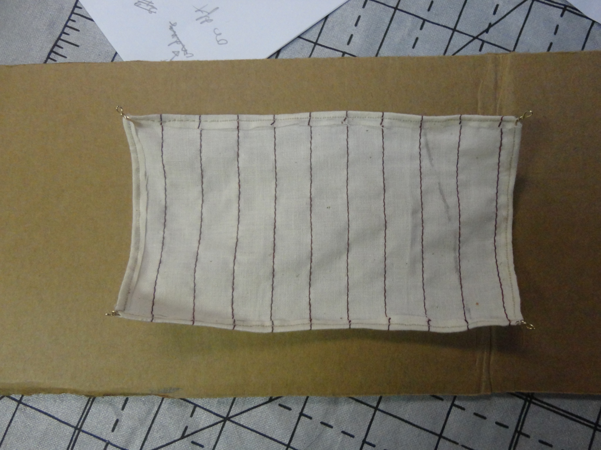
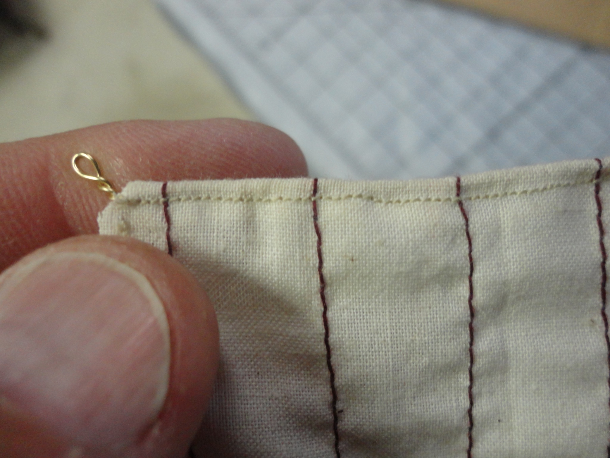
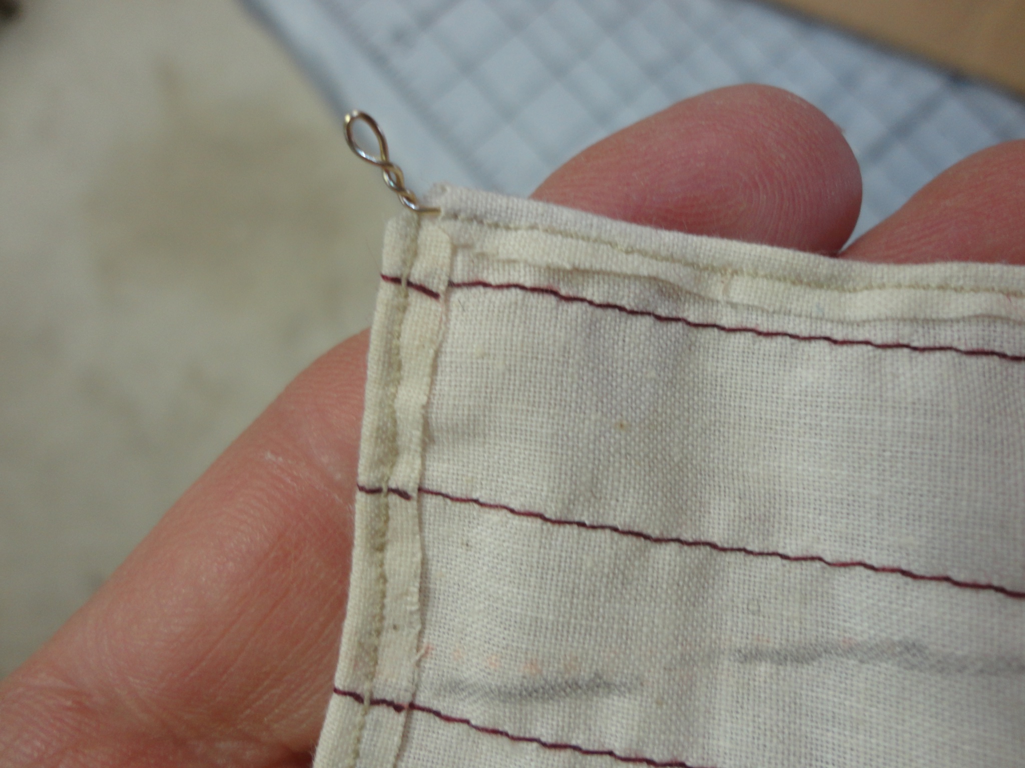
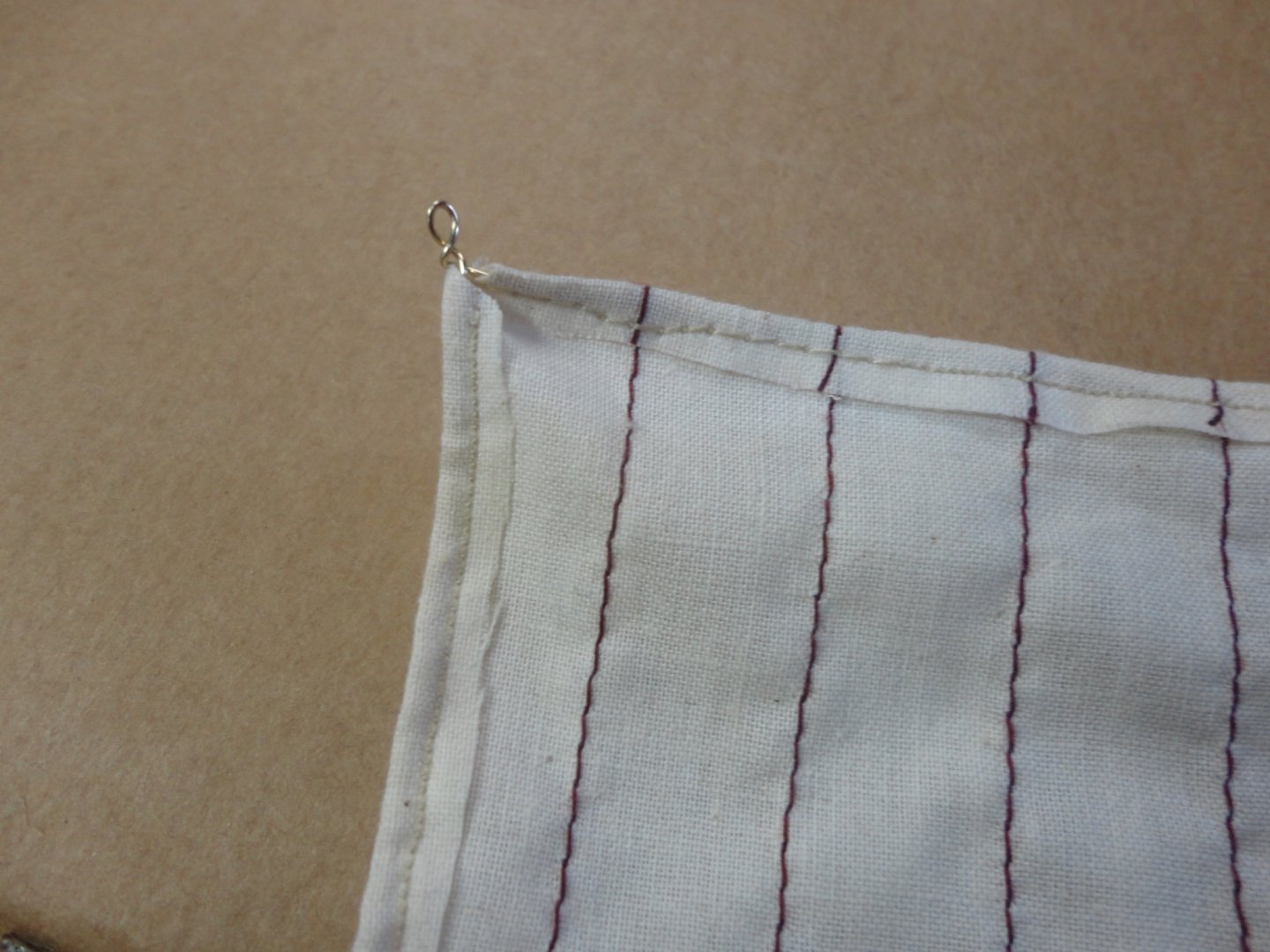
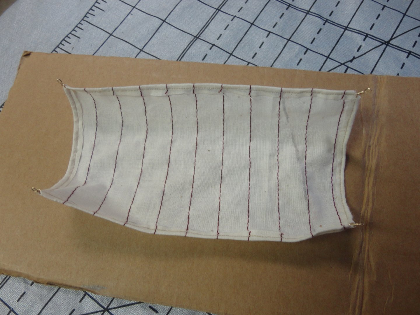
Ahoy! You started Johnny thinking about making sails, and some likely ideas came to mind ... and I thought (versus said) to myself, THIS time I've got to try one of my own ideas before suggesting them on the forum. Except for the full sized sail I made for my 12' Viking dinghy years ago (and sailed her too!), I have not made a model sail before. The idea was to use fine natural muslin, and that can be had in a fabric store (the Admiral got some at JoAnn's) - and it is at least 100 threads to the inch. So I fooled around with the Admirals sewing machine (a mid-grade Baby Lock with touch panel) and a scrap of muslin. She had burgundy thread in the machine, so I used that at the default 2.5mm stick length and sewed parallel lines by eye ... the presser foot was a handy guide. Johnny sews piecework of various re-enactor supplies, but he's got an old manual Kenmore thats been through the wars, and is otherwise a 'hack' sewer. This exercise is intended as a 'proof of concept', since I felt that I could do a lot better than the stock OcCre sail in my Endurance kit. Not that they are all that bad - and certainly a convenience for anyone without a decent (like the Admiral's) sewing machine or even knows how to sew. BTW I like thevbBeagle build you did, and want to get the kit for my stash. OK, once the vertical lines were sewn I realized that I could change the stitch length way down. 'Tried some at 0.2mm - but it turned out to be more 'theoretical' than practical. The setting of 1.0mm actually produced 33 stitches to the inch (0.75mm) , which I used around the perimeter with 'natural' thread. WOW, that actually looks nice and works out to a 'scale' (at 1:50) of about 1 1/2" long stitches on a full sized vessel. That is still a little large, but looks just fine to my eyes. If the vertical stitches were done in natural thread, it would be perfect. Compare the following photographs to the 'stock' sails in the kit. Now I didn't want the edges to fray, so I used a product called 'Fraycheck' - also found in a sewing store (or on line). It dries totally transparent. You can see the dark lines of stitches (again, just for this sample) which are 2.5mm (still too large, but I didn't know what I was doing at first), and compare them to the 0.75mm stitches around the edges. After the fray check dried, I pressed the edges one and clipped the corners, before sewing them down. Now then I took some 24 gauge brass beading wire from the Admirals supply and fed it through the pocket - making loops at the corners as I went. (I made one loop first to serve as a clew, fed the wire through one straight section, then made a clew by winding the wire around the narrow part of a dental tool.) In the above photo, the stitches started at 2.5mm, then I reduced to 0.75mm - and you can see how fine the smaller stitches look. The stitches on the left are 0.75mm. It is a trick not to 'kink' the wire when feeding through the next pocket along the edge. When the wire ended at the home position, it was just wrapped once around the clew and cut off with flush cutters. Note that bead working tools like fine, tapered round needle-nosed pliers (and the like) are very useful. (Thanks Admiral.) She 'caught' me at her machine, but was amused at the title sail I'd made. You can see that with the wire in place, one can gently bent it to simulate 'wind in the sail'. This is only a test piece, as mentioned above, and beading wire is available in many colors ... including shades of brown, so one would use brown colored beading wire (24 gauge) to made the clews - which I could have done a little finer with practice. But hey, this is a Johnny idea that has actually been tried! Below is the sample sail seen from the front at a corner. In the above photo the fine stitching is preferable to the coarse, and the Admiral says that if I pick a finer blond thread that what I used, I could probably make the 0.4mm setting work. - that would probably yield 0.3mm, which at 1:50 scale would be 15mm - or .6" stitches ... with approach real-life size range. (Don't know if I want to go that far, but she says that there are finer muslins approaching 200 threads to the inch!) Below is a corner from the back. Now the Admiral says that if I'm careful to press the edge over a little once, THEN press it over again before sewing the channel that runs along the edge (to feed the wire through), there will be no 'raw edge' - which is more like the real thing. Fray check is still a good precaution either way. I'm curious to hear what fellow builders think of this approach. Fair winds! Johnny


-
Ahoy! You've got me thinking again ... (I thought I smelled wood burning :D). Carpenters' nail sets (for tapping finishing nails below the surface of wood trim/millwork so that putty can be applied, then painted over (after the putty dries) are used so the wood work appears seamless with no fasteners apparent. OK, so I noticed that the working end of the hardened steel nail set has a spherical depression in the center and a tapered exterior that produced a circular edge to 'bite' into the small head of the finishing nail. This is so that the nail set won't 'walk' or slip to one side of the nail head (or side off the head altogether), which would further mar the woodwork (and require more putty). Now I suppose that the tapered exterior of the tool's nose could be ground or honed thinner so that this circular grip would be transformed into something like a cutter. Nail sets come in a variety of sized to suit the various diameters of finishing nails (8 penny, 6 penny, 4 penny), and some of them may be about the right scale for a tree nail of various scales. The modified nail set could be hand applied (with care) or even tapped gently to put a tiny ring-shaped cut into deck (or other) planking. Finish applied over a deck so marked would tend to accumulate more in this ring shape (but not too much more) and it would imitate caulked tree nails. Please note that this is old Johnny thinking out loud (or talking to himself again) with another idea he has yet to experiment with. Now I suppose that before using the nail set, one could apply a surface resist (a thin coat of shellac is one of my favorites for wood working in general), and THEN use the nail set. One could wipe a darker stain or filler that would seek the tiny circular recesses, yet tip away from the top surface that has been sealed. Scale, of course, would be the limiting factor. Johnny
-
I've used PVA for bookbinding because there is a slight 'flexibility' on the spine (built up thick) when cured. The book needs to flex without 'cracking' or breaking. When used thinly on paper on a porous substrate it is permanent alright. I think it would be better to use for deck planking that any contact cement, while carpenter's glue (Titebond) would be preferred for structural work (frames, bulkheads) where rigidity is required. Contact cement can de-bond over a long time frame, so I don't know why (other than for short-term convenience in some applications) it would be suggested by any kit manufacturer. Now I've considered a use for PVA to take advantage of some residual flexibility, yet permanence between flat porous surfaces - making my own thin hardwood plywood to use for planking (especially for ships where the natural wood will show, that is, unpainted or mostly unpainted). I have the Billings improved Oseberg kit, and the only thing I'm not crazy about is that the laser-cut strakes are made of bendable (formable) plywood where the exterior layers (each side) are of a nondescript 'white' wood that require staining after assembly. And while that can be done with care, I'm not crazy about the look of 'stained' wood. The old Billings kits (Vikings skibbe and Roar-edge for example) supplied mahogany - but the builder had to cut it out (time consuming) and as a single veneer the wood was prone to breakage along the grain. The original version of the Wasa (1:100, which I'm slowly building after many years of the planked hull on the shelf) had mahogany planking that did bend pretty well (single planked, no less) and looks beautiful as-is - no staining needed at all. OK, so I'm going to experiment with some typical thin black walnut veneer, and use three layers: one running at about a 30 degree angle one way, the middle layer vertical and the third layer at 30 degrees the other way. I'll brush on some slightly thinned PVA (water is the thinner) before assembly, perhaps running a very fine notched trowel (or equivalent) so there won't be too much glue, then press everything together on a flat surface with a board on top and a bunch of books for good measure. Once cured (like overnight), I believe that the resulting stock will be easy to slice (with a jig) using multiple X-acto cuts into whatever plank size I need for ordinary hull second planking - and the residual flexibility of the PVA will allow for forming without much risk of delimitation or breakage along a grain line. Other glues such as epoxy or carpenters glue dry too 'stiff'. In the case of the Oseberg, I'd have to trace around the strakes provided and cut out (like in the old kit versions) ... but this time the planking should be doable without breakage AND there will be a natural heartwood color that I find so attractive. Of course it could be lightly oiled to darken it somewhat, but it would still be the real color of the wood and the oil ('boiled' linseed, thinned a little with serpentine if desired) is a traditional finish I have used on reproduction match locks and flint lock rifles. A little rubbing with a fine cloth gives it a nice sheen. Now this is another 'Johnny supposition' that I think will work based on past experiences with other applications using PVA. 'Now its time for us to say good-bye - leave her Johnny leave her. The old pier head is a-drawin' nigh - and it's time for us to leave her. Leave her Johnny, leave her. Leave her Johnny leave her. Oh the voyage is done and the winds don't blow and its time for us to leave her.' Fair winds ... Johnny
-
Ahoy! your illustration puts me in mind of what I'll have to do to improve 4 of the five vessels in the new OcCre Endeavor kit ... Other than the title ship, what vessels are those? Why, the 4 life boats - which are all built on frames with planking at 1:70 scale. In fact, before trying to dive into the main event, I want to have a go at the lifeboats - and we're fortunate to have specification on the three use by Shackleton to escape from the Antarctic. The examples 'out of the box' are simplified (reduced # of ribs) - but still must be planked, footlings and thwarts installed and topped by an overly thick gunwale without any curve to it. So the 'bashing' job to take these small boats to the next level will be to put the gentle curve into them, as well as make them more to scale with what we know about the originals - and one of them survives to this day and can be seen in an English museum, the James Caird - a double ended life boat 22'6" long, 6' beam and 3'7" depth. The 4th boat not salvaged was apparently one of the same design as the James Caird. The other two boats had transoms: The Stancomb-Wills had a small transom and was 20'8" long, 5'6" beam and 2'3.5" inside depth. The other was the Dudley Docker having a larger transom - 22' long, 6' beam and 3' depth. All these lifeboats appear in many pictures of the ill fated expedition, and show a number of angles, how they were braced on davits when sailing and how they were modified and used for survival and escape. The framing will have to be modified to suit, and they can be equipped with oars and supplies - as well as eventually mounted where they were on the Endeavor as seen in photos. Hmmmm, sounds like a project. Johnny
-
Overall, a great job so far. Thanks for the tips on symmetry (or lack of it) on the stepped stern filler layers. One possible assembly technique might to 'dry fit' all the pieces to see if they are stacked correctly, then mark the top surface (actually that which faces the keel since the model is flipped for this assembly) plus R or L as each piece is removed sequentially - layed out to either side so they can be put back in the proper order with glue.
-
I'm relatively new on this site (and not that computer savvy), but what has worked for me is to have the images on the desktop (I'm on a Mac mini). I'll put some text in a log entry, then hit the spacebar several times to create 'blank space' below the text. Then I'll drag the desired photo into the empty space I've created (not the bar on the bottom). The photo has thus far been inserted into the empty space (and also a 'record' of the insertion in the bottom panel). Then I move the cursor with the mouse to the bottom right corner of the image just inserted, then hit the spacebar to add more 'empty space' below the image. Then I can type more text and it appears below the image already added. This process has been repeated to add a number of images. Note that there will still be 'duplicate' icons of all images in the 'panel' (bar?) at the bottom. You can ignore those. Johnny
-
You are indeed correct ... I never quite 'got my head around the math' of scale, and see now that fretting about infinitesimal marks on a hull below the waterline does not make for much fun in building - especially since the details ABOVE the water line are far more important (like rigging). Yet in some applications, a few items (judiciously) not quite to scale can lend a lot to the overall effect of an intermediate level build. For instance, if you peek at my (old Billings 1:100) Wasa build - I put in rows of round toothpicks where the bulkheads are (I was a teen then) as 'tree nails'. They are larger than scale tree nails should be, but still the light tan ends of toothpicks go well with the natural color of the mahogany planking. I'm rather happy with the look of it, even though ships so constructed have a lot more of them - and it seems the Wasa planks were nailed with iron rather than tree nailed. My job with recent work has been to correct major defects in the early version of the kit (loads more is known from Wasa reconstruction) in order to nudge the project closer to the prototype - but one can only do so much, yet still end up with something attractive to display.
-
Anyone out there working on a card model?
Snug Harbor Johnny replied to gagliano1770's topic in Card and Paper Models
Ahoy mates! You've jogged my memory enough to make me remember a paper model kit of the U.S.S. United States - a postwar luxury ocean liner originally built for speed with turbine engines. I think I was 8 or 9 years old, and the model I was able to make from the die-cut thick-stock color printed paper looked pretty good to my eyes. I can't remember whatever happened to that model. A few years a go I went down to the Philadelphia docks to view the United States tied-up in a state of limbo. I think the choice was either to turn it into a cruise liner (with standard engines as the turbines were reported to have been already removed) if a buyer could be found. Asbestos removal might have been an issue. Johnny -
I do some piecework Colonial soldier hats and haversacks for a supplier of American Rev. War stuff for re-enactors. He said that he lost his source for brass castings of buttons and buckles of various sizes, and the one he's forced to use (India or Pakistan - not sure) has sent items with a similar decrease in detail and workmanship. My guess is that they made new molds of some type (but cheaply or by an inferior process) from the good samples sent. The 'new' stuff from the foreign supplier just does not look as good as the stuff made before. A mold wouldn't suddenly go from good to 'so-so' overnight. Next time I deliver product I could try and get clarification on this. BTW he also lost his domestic caster of pewter buttons, and had to find someone else - except in this case I think the molds were returned from the guy who was retiring aft a long time doing buttons.