HOLIDAY DONATION DRIVE - SUPPORT MSW - DO YOUR PART TO KEEP THIS GREAT FORUM GOING! (Only 36 donations so far out of 49,000 members - C'mon guys!)
×


Snug Harbor Johnny
-
Posts
1,466 -
Joined
-
Last visited
Content Type
Profiles
Forums
Gallery
Events
Everything posted by Snug Harbor Johnny
-
 'Really like your brass work ... my thoughts were that brass might need soldering, but glueing seems to work fine ! I take it that you used CA glue? Perhaps the railing through the stanchions might look better with brass wire opposed to the rigging rope. I'm favoring the use of brass anywhere on most ship models, since brass will form a natural brown patina over time all on its own ... and it looks sharp besides. The view from above over the life boats is way cool, and I'll continue to pay close attention to both current Endurance builds for tips and ideas to use when I get to mine. Thanks mate! Johnny
 -
There was one clip I saw where a credible ship's wall was built for a naval gun test with solid shot, and there were quite a few splinters and shard sent flying. Any round hitting a gun or carriage would disable that piece.
-
Old planes not fit for 'restoration' can be had at reasonable prices on the U.S. east coast at antiques marts ... Southeastern PA has many in an arc well-away from Philadelphia. Useable boxwood for model ship work can be cut from these plane bodies. Nes pas?
-
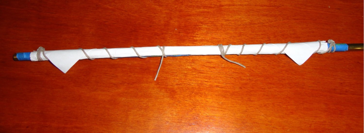
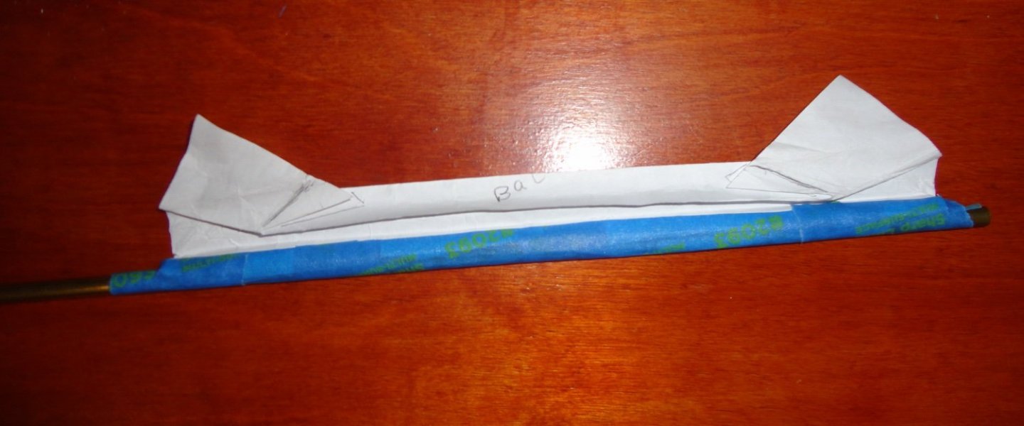
Grommet lines added. The view is angled more to the top of the yard. When viewed straight-on from the front, the blue tape (yard) is seen - but there are no raw edges of sail since it is accordion-folded. The lines are just some waxed linen awl cord lying around - not rope at all, which I intend to make myself. As mentioned, this was just an experiment to see how something like this might work - and I think it should with fine cloth, and look presentable on a ship represented as docked. With un-done grommet, the sheets pull the ears down and the sail unfurls (although the paper retains creases). Actual sails in real life behave much better.

- 399 replies
-
- 4
-

-
- cutty sark
- revell
- (and 2 more)
-
OK, I'll try to add the next picture. NOTE: didn't load again, but it has 5.3 mega byte, and the others are less. 'Took a break to open Photoshop and crop the image to try and reduce the file size. Let's see ... YES ! Since I reduced the mb of the image, I didn't get the "upload fail" message I had before. Some have commented on this forum that they were failing to get pictures uploaded to posts, with a message of a 'server error' (200) ... I think I've found out that there may be a practical size limit to the picture one tries to post. The picture below has the yard flipped right-side-up again as to viewed from the front - and the gathers were restored on the previous fold lines, and the furled sail is ready to lie on the yard and have the 'ears' descending in front. The next picture has the grommet lines added.
- 399 replies
-
- 3
-
-
- cutty sark
- revell
- (and 2 more)
-
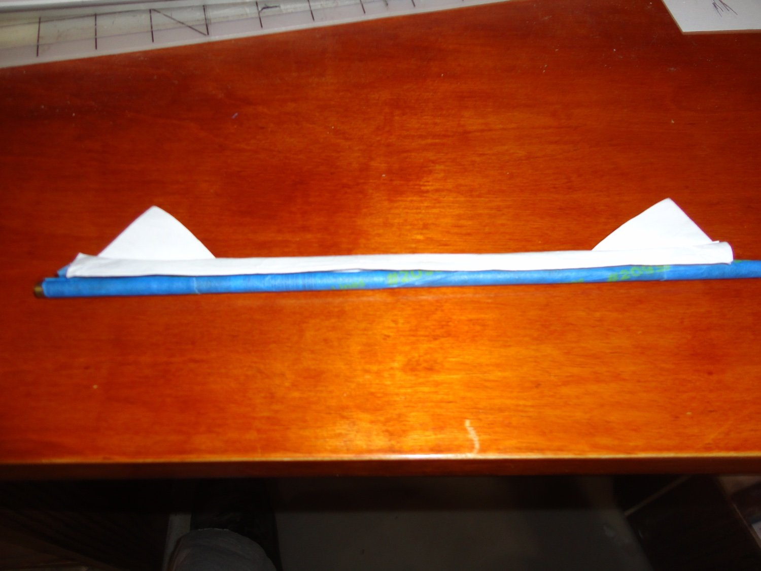
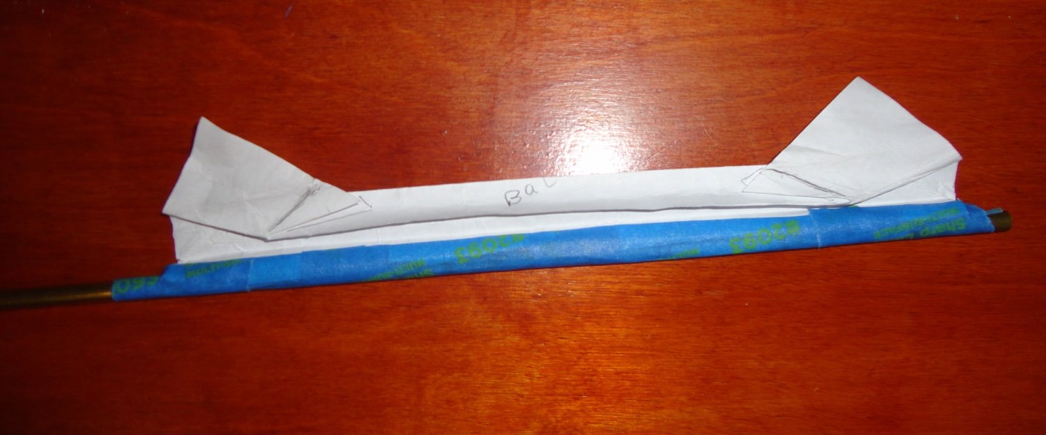
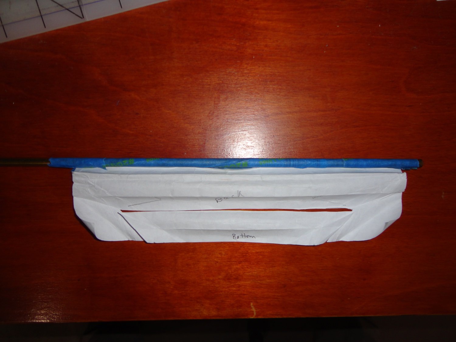
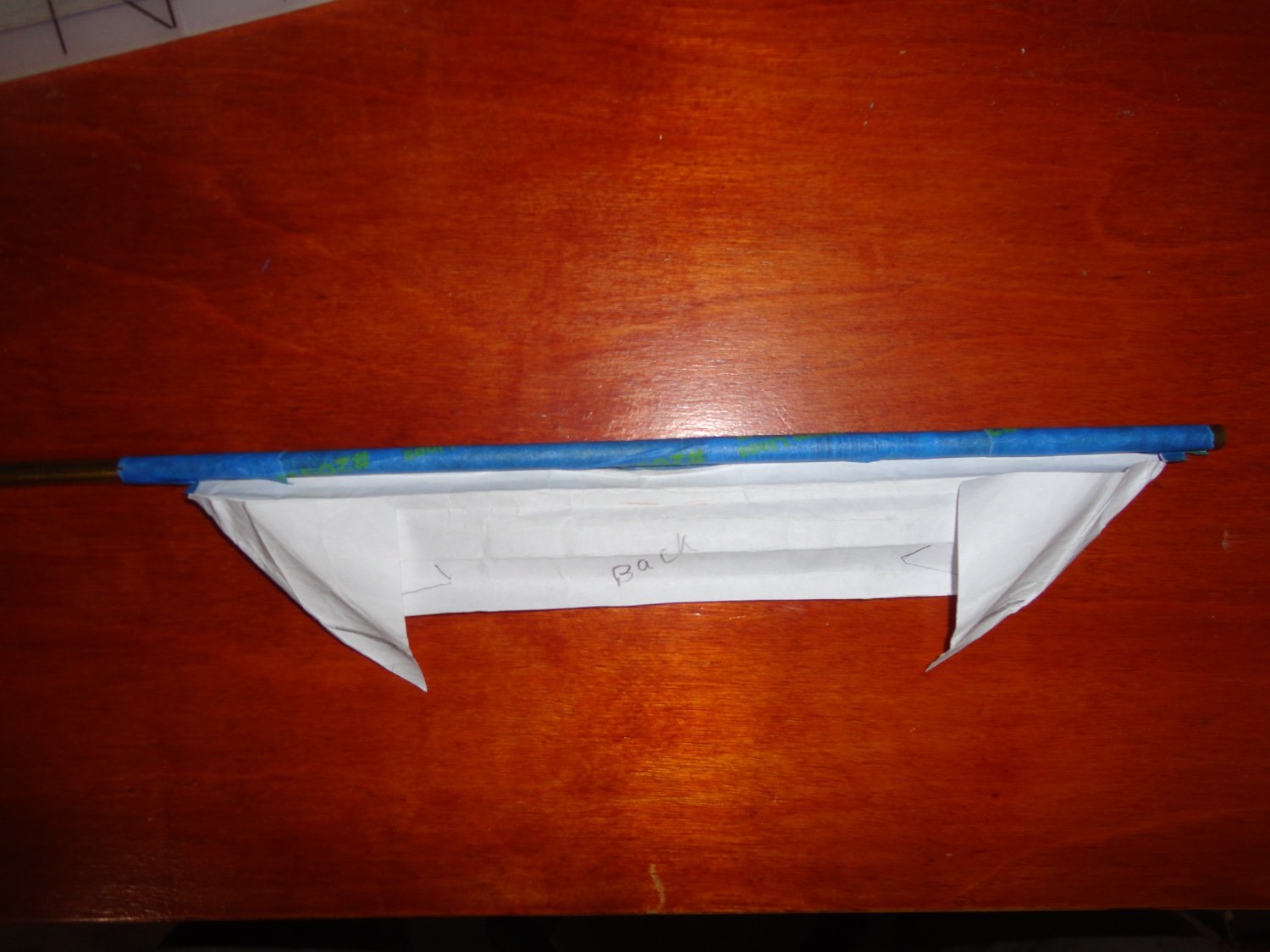
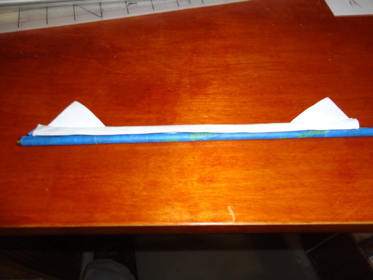
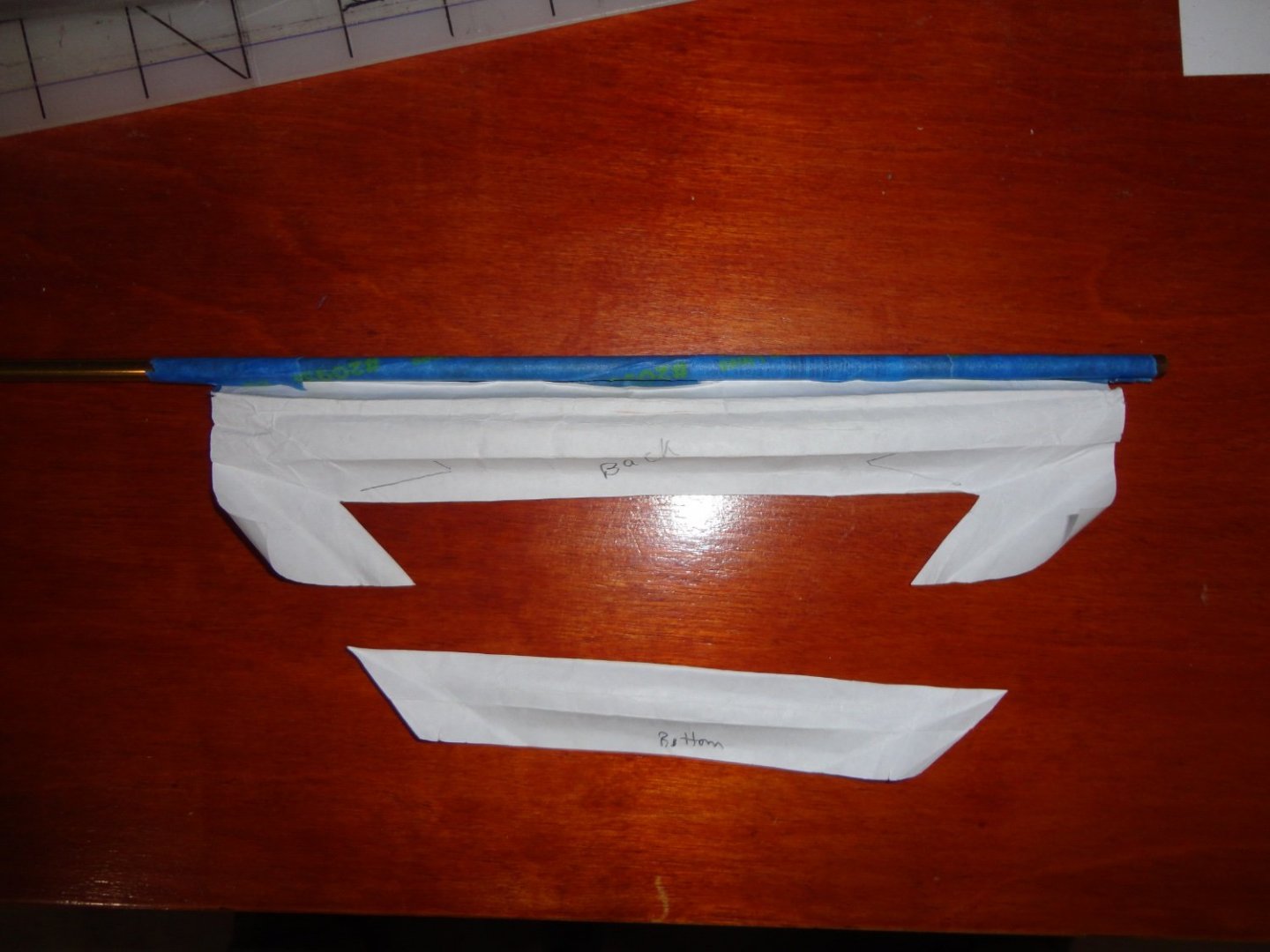
'Saw an interesting post a while back on folding a strip of thin cloth to represent a furled sail on a clipper ship yard - to reduce the bulk that results from trying to fold-up a full sail, since just about any fabric is way out of scale at 1:96. 'Mouse ear' (or dog ear) pieces were added to attach clew and sheet lines - these are the bottom corners of the sail that hang below the furled sail near the yard ends. Yet another post had a side-view diagram to show how bunt lines drew the bottom edge up the front of the sail, then crewmen standing on the foot ropes would gather some of the sail and pull it up over the yard (leaning forward to pinch the gather to the yard with the waist), then gather more sail to make pleats on the top of the yard. There were links to present-day clippers with furled sails appearing rather compact and neat. A length of line (grommet) is spiraled around the furled sail to keep it in place. Another source indicated that when sails are set, the grommet line is coiled and hung as convenient on the mast or trestle ... so ships modeled with set sails might include a few coils in those places. The sheets are hauled and they pull on the 'ears' to make the entire sail flop down and open up (the clew lines having been made loose to allow this). 'Kept thinking on a procedure to furl the sails from the start - and how to replicate it on a model - so I fooled around with paper taped to a brass tube (simulated yard and clipper split topsail) in 'origami fashion'. I finally got a reasonable facsimile that pleat-folded over the yard and had the actual corners of the sail just hanging down over the yard as I've seen in some pictures. (I saw another contemporary picture where they were done a little differently.) Tugging on the ears does indeed make the sail unfold, so I thought there must be a way of reducing the bulk without resorting to adding separate 'ear pieces'. Cutting out a trapezoid along a fold line seemed to do the trick. There are several modeling advantages to having furled sails. First, the jackstays are covered over - so one does not have to make them at all - which is rather fussy in 1:96 scale. The blocks for the buntlines are also covered ... so one can even omit the lines as well since the blocks are not seen (and so omitted entirely), and there will not be such a 'jungle' of lines going down to the pin rails. Ditto for luff lines. No short reefing ropes are needed since (if they were on the sail) they would be folded up inside the furled sail. The rope sewn around the edge of the sail will only be seen on the 'ears', so only has to be put on at the corners. Also, clipper sails are bent to the jackstays (not the yard), and since the jackstay is covered by the furled sail - one need not bend the sail at all to the non-existent jackstay. One WILL show the clews and sheets, plus lifts and braces - which will provide plenty of lines and blocks to properly mount on the model. Now I did take a few photos (one picture is worth a thousand words) to show this 'proof of concept'. The first one shows the paper sail taped (bent) to the yard (tubing) with blue tape. The lower corners of the sail are 'curling up' some, as the paper had been furled and unfurled a number of times. Also, the above mentioned trapezoid of paper that had been cut out to reduce bulk is positioned in its original place ... When doing the model, I have some VERY fine silk (also fine linen) that will be used for the furled sails. The next picture shows the trapezoid moved out of place. The shot below represents the corners of the sail pulled up by the clew lines OK, the next pic has the yard flipped over and inverted (as if one was leaning over the yard from above) ... Remember that originally the entire piece of paper representing the sail was pulled up from the bottom (which the bunt lines would have done), and a couple of gathers were done - folding each one (creasing the paper). Then the corners were re-positioned outward a bit, which changed the folds on the paper - but did not compromise the 'sail' at all and no cuts were required. There are a couple of pencil marks where the folds changed, and I have yet to re-fold the final gathers. (Hmmm, photo limit reached, so I'll have to 'submit', then continue.


- 399 replies
-
- 4
-
-

-
- cutty sark
- revell
- (and 2 more)
-
From the 'kinking' seen on the right side rope, it must be wire rope. My guess it that they pulled the rope through the stanchions as far as the space where the anchor goes over the cathead. 'Can't imagine them trying to pass the anchor under the rope. I'm almost certain that I saw another picture en route to the arctic where that section had been altered so that a piece of regular rope went between those particular stanchions (clipping on an 'eye' on the wire rope, the eye preventing the wire rope from passing back through the hole in the stanchion) - which is how I'd have ordered it modified ... but I can't lay hands on that picture right now.
-
The build log for Glory of the Seas (a long log indeed) has a section on a cool way to use copper tape - first passing it through a embossing process using an old-fashioned clothes wringer. Rob's log of Great Republic also goes into this method. Wringers may still be marked to the Amish.
-
Jason, Hull considerations aside, the care in rigging is what can show a model to its best - so the books on rigging suggested elsewhere in the forum will take precedence over the simplified version found in the kit's instructions. Once again, Bruma shows so many details in this area - and using real deadeyes, rope shrouds and ratlines are a standout. I've pondered how to do this on the gunwales molded on the bulwarks ... possibly drilling small holes for the wire wrapped around the lower deadeye to pass through and continue downward as the chainplate. Small notches would be made in the largest rub strake (could be filled afterwards) with an eye formed at the end of the wire to fasten through the hull with a tiny brass pin (predrilled hole). Of course, there may be a way to use the kit deadeyes but add rope shrouds instead of the provided plastic ones. The Cutty Sark has metal plating as the upper part of the bulwark, versus the wood of Thermopylae. Cuttl Sark also has a second proud strake below the gunwale (painted white) that is not present on Thermopylae. I'm considering dremeling off that bit and abrading the rivets (but keeping the port indications as-is), then using an engraver (or fine awl) to make plank lines and perhaps an indication of wood grain. Since the hull is painted it should look OK and be closer to the original. On the inside of the bulwark there are triangular bits down the sides that could be removed. A wood 'waterway' plank can go at the bottom so it will stand slightly higher than the wood deck to be applied. CA or epoxy will bond wood to plastic. Checking out the build of the Glory of the Seas talks about waterways (and a lot of other things as well). So here's my 'rabbit hole' - The molded gunwale is a tad narrow for the above mentioned hole-drilling, so it could be abraded off, the inside of the bulwark planked with thin strips (CA or epoxy). Vertical wood ribs would go next (wood glue for wood-to-wood), only part way up where any pin rail will go. I'd fashion wood pin rails (pre-drilling for whatever brass (possibly wood) belaying pins acquired and gluing to the bulwark, then add whatever ribbing to go up to where a new wider wood gunwale will mount. The area at the bow and stern where the railings go do not have gunwale on the hull, because the provided gunwale sections in those areas have stanchions for rope or wire railings. These could be used as-is. I suppose wood gunwales could be put there and 3-D brass stanchion used (Cornwall Boats is one source) ... All this would be quite a modification for a first ship, and using the provided pin rails and railings is certainly a less daunting way to go - also much less time consuming. You'll be spending time doing rigging to whatever level of detail you care to get into. I'm involved in a lot of things in what is turning out to be a 'working retirement' ... too many hours at the hospital as a Pharmacy Technician, teaching one night course and also a teachers aide at another night course, home improvements/maintenance, doing most of the shopping/cooking/cleaning to help the Admiral - who makes goods to sell on ETSY with me as shipper and bookkeeper, and managing some rescue parrots. Somehow there may be a little time here and there for model ship work - my build of an old Billings Wasa has been suspended for a while, but I now know where I want to go with it (masts only up to where they are at the museum in Stockholm, as if it were under construction). I also completed a build of the U.S.S. Arizona from a Metal Earth kit (tiny, but with a fair amount of detail). Both are on the forum. Johnny
- 399 replies
-
- 3
-
-
- cutty sark
- revell
- (and 2 more)
-
Ahoy, Jason. I also have an old Thermopylae kit (late 1950s, so the parts are pretty clean from fairly new molds) in store for building when current projects are done. Bruma's techniques and 'busts' are great - like reinforcing the bowsprit internally to avoid bending when rigged, and replacing the dolphin striker and the 'whiskers' on the catheads with stiff metal wire (can be found in some hobby stores) - as thin plastic is sooooo prone to accidental breakage. Since I've never been all that happy with plastic thats been painted wood color, there is a thin laser inscribed wooden deck made for this model (as well as the Cutty Sark) ... I found them on Ebay from an Eastern European source and obtained the one for the Thermie. Also obtained is a small photo etch sheet having the name to go across the stern (plus a couple other things), as the decal would be sure to 'crumble' if used. Some claim to have used a decal 'restoring' product - but the technique may be tricky. Altering the bow curvature to an "Aberdeen" shape won't be hard, but any changes to the angle of the stern involve a lot of complications. Same goes for altering the quarterdeck further forward to where it was on the original. As-is, the adaptations of the Cutty kit into one for Thermopylae was a 'reasonable' compromise by Revell - the rear cabin is about right and the deadeyes are mounted on top of the gunwale (as opposed to inside the gunwale on the Cutty) with approximate exterior chainplate. There is an option for barque rigging as she was for the five years of timber trade in the Northwest ... and I'm considering going that way. Adding thin layers of white until just a hint of the green shows beneath might simulate the weathered paint job she had before being sold abroad. Yet she looks best in the green of her prime. Neither kit has booms for studding sails, but this is not an issue for me since sources indicate the discarding of that tackle once steamers taking the Suez canal meant that maximum speed was not essential for clippers. Rather, crews could be cut to keep them cost-competitive for bulk cargoes like Australian wool. I'm not planning on sails either - unless represented as furled using narrow pieces of material to prevent 'bunching'. There are a lot of possibilities to choose from, mate. Fair sailing ! Johnny
- 399 replies
-
- 5
-
-
- cutty sark
- revell
- (and 2 more)
-
What's Your Favorite Hobby Supply Store?
Snug Harbor Johnny replied to Dave_E's topic in Wood ship model kits
I sometimes find old kits or partial kits at a flea market - sometimes at a train show/hobby show that is not super-strict on dealer/member 'swap table' items. One incomplete kit I inherited (yes, check-out estate sales) has a dozen canon on pretty good trucks, but the cannon don't suit what I'm working on. What I'm working on has lousy trucks for great looking guns, and when I popped a barrel off one of the better trucks and installed the gun barrel of my project - the result was a big improvement. (Note that there are half-barrels protruding from lower gun ports on my model, which is why everything should match.) Other orphan kits can have better blocks and fittings - also the nicest planking I've found in some of the old kits. Sometimes nice rope - often times, not. I've found pretty good ship's boats in various scales in old kits - some good as-is and others can be enhanced with a little creativity. Other finds include gratings, ladders or ladder components, deck eyes, hooks, tiny nails in steel or brass. Then again, one may find an old ship model in sad shape that has good salvage fittings and stuff ... unless one wants to revive and improve a perfectly good hull with better fittings and rigging. It's all up to you. -
Bravo Clearway - I've managed to find the stern photo in dry dock you mentioned ... Yup, a 2 bladed prop - and there is nice detail on how the rudder was hinged. It does look like there are metal plates on the periphery of the rudder going down to the level off the prop. There's no indication on what material was used (same with that on the leading edge of the keel), but perhaps it might have been painted steel - which would hold-up better than copper for the presumed purpose of reducing ice damage to the wood at those locations ... just a guess. The photo has excellent detail for the steering mechanism, and chain is wrapped around the horizontal drum. There is other good stuff, like the relative planking width (among other tidbits). Too bad there isn't ONE source or reference having all the known photos of Endurance together. There are a lot of old photos that have been the 'public domain' for some time - yet many museums, institutions and individuals are now claiming 'copyright' on the same photos ... I suppose 'just because they can try'. And there are sometimes multiple 'entities' claiming 'copyright' to the same photo. 'Gets me, since under the old laws copyrights had to be renewed at intervals and there was an absolute limit to the number of times this could be done. Once expired, material went into the public domain - and there are a lot of photos the were used for postcards in the early 20th century that never had a copyright in the first place, ergo they were public domain from the start. But the Disney lobby feared that their oldest movies nearing the limits could be openly copied and sold as public domain. This is aside from the fact that their images are registered 'trademarks' (look closely at Micky or Goofy and you'll see a little 'TM' somewhere), and those can be indefinitely renewed and can protect from 'copycat' images - even if original art. So the laws were changed so that a copyright holder has absolute rights for life (plus so many years for the estate) ... yet if the holder is a corporation, then as long as the corporation 'lives' (files tax returns) the copyright now holds effectively in perpetuity. OK, so one better have a license to sell any old movie. But as a result of re-writing the copyright laws, all kinds of entities and individuals are slapping copyrights on anything they happen to have. Different prints of the same old postcard will have different postmarks, scratches, stains (or whatnot) - and many claim that their 'version' is thus unique and copyrightable. Sadly, they overlook that once in the public domain - something can no longer be copyrighted. So the question revolves around whether a photo was published in a book or on a postcard or in a newspaper that was either not copyrighted or that the copyrights expired on. Photographs that were never published at all, but are in private collections may well be fair game for claiming protection nonetheless. Not affected is the 'fair use' doctrine - that if one buys or legally acquires a book or publication, one has the right to use it for personal reasons (including copying, enlarging, modifying, etc.) ... but not to reproduce for sale or distribution. Yet the original item can be sold to someone else, effecting a transfer of the single copy license. Fine lines, for sure - and anybody can sue anyone for anything. (Doesn't mean they will prevail.) Sorry to have gone into this 'rabbit hole', and Old Johnny is hauling himself out with blocks and tackle.
-
I'm learning more about the Endurance all the time - hence I'll wait until present builds are finished (and look for more info in the interim) before thinking about starting this project. I didn't know that she had a few plates at the bow (presumably to lessen ice wear on the keel), and she may well have had some at the stern. There are pictures of Polaris (before being modified into Endurance) that show the rear railing with three rails (versus the two that were on the Endurance - and the top rail being wood !). Polaris had a much smaller rear cabin and a photo shows no channels. Initial conversion to Endurance shows the enlarged rear cabin, channels for the deadeyes, the new name on the stern - and the ship above the waterline is still white ... but the kennels have not yet been built and there is no enclosure over the steering mechanism. I surmise that there was more work done subsequently to that photo (perhaps in South America while fitting for the expedition). That additional work included the kennels and steering shed - as well as painting the hull black above the waterline (rub rail excepted). My guess is that a black hull would be far more visible in the arctic than a white one - especially if there was anticipation that the ship would have ice all around, and scouting parties would need to see the ship from afar. So there are 'several' versions of the ship that can be modeled ... as Polaris (pre-conversion - and there are photos to go by), as a 'phase 1' conversion to Endurance per a few of the photos I've seen - and the hull would still be white then, or as the ship was finally modified just prior to setting out for the Antarctic (with a black hull and white 'pinstripe'). One could model it stuck on the ice, when the steering house was removed to be used for the first encampment - as well as stripped of some other stuff, and three of the lifeboats named and further modified. Check out the considerations surrounding the present build of the Glory of the Sea - and how there are separate time periods with their own modifications to choose from. The builder obviously had to make a choice among the many options. Same goes for the Thermopylae, that went from China tea clipper (maximum sail for speed and 'token' cannons as required for insurance) to Australian wool trade (where studding sails were discarded and mast height lessened since top speed wasn't essential, and a smaller crew kept her competitive with steamers - she also got re-painted green that covered the previously distinctive yellow rub rail) to working the Northwest timber trade where she was painted white and converted to a barque, to being outfitted as a trainer for the Portuguese Navy, to being used as a coal 'hulk' ... and ultimately sank as a Naval training target. ALL these were the same ship in a variety of forms, so whatever ship one wants to model - deciding what time period to represent will affect how one outfits and rigs the vessel. The search for knowledge is half the fun, as I see it. More to your point, had the entire hull of the Endurance (Polaris) been coppered below the water line - why would any owner gone to the trouble of removing all of that? Polaris was built for northern waters (gad, it had two feet thick sides! ... and only the Fram - used by Amundson - was stronger, per the builders) so ship worms only live so far north due to temperature extremes. The second factor is the development of effective anti-fouling paint - and that could be an avenue of separate research. But with a cheaper alternative than to copper an entire hull (just slap on the paint), they likely used metal only where deemed necessary for protection from ice - hence the prow and concerning the steering mechanism. My guess. Fair sailing - Johnny
-
Step one could be to remove the 'good wood' keel added. Since it appears straight you could support it on a table edge (after having a fine pencil line drawn to the trim point on the plywood as Harlequin suggested), use a metal rule as a guide (with wood planking to position it just about even with the GLUE line) and make successive light cuts with a fresh Xacto blade at the glue joint to free the keel piece. You'll need to support the hull hanging over the table edge with a stack of books or wood put on a chair before proceeding. If you have a 'miniature' modeler's plane - or better yet, a 'low angle' hand plane - (the blade must be quite sharp) plane away the unwanted plywood until the pencil line just disappears. As was said, the keel appears flat, so with a SHALLOW (real shallow - so test on scrap wood to produce a thin curl) blade setting, plane all the way across the plywood keel with each stroke. No plane (or planing experience)? Then use the Xacto cutting method to cut the keel where the pencil line is to remove the 'good wood' keel WITH the offending strip of plywood attached. Then trim off that unwanted piece from the 'good wood' keel on a working surface. You can make sure the remaining plywood keel is flat by lightly sanding with fine grit wrapped over a long straight piece of wood as a sanding block - moving the block straight down the keel until no trace of the pencil line is seen. The 'good wood' keel can be trued by working the cut edge against fine grit sanding paper on a flat work surface. Re-glue the keel together and ... you've got it.
-
The view from the quarterdeck has many fascinating details... The foremast yard is turned a bit to port, showing a pair of blocks that appear to be for the topsail sheets. The topsail is all wrapped up around the 'automatic furler' mounted below its yard - the mouse ear (some say dog ear) has a sheet line that you can trace down to what may be a pulley inside the main yard, then the line loops over to the aforementioned block. There is no main sail mounted, but the block for the clew line is at the end of the mast, with the line likely 'stopped' at the block, but it can be followed to the mast to a block concealed by the mast in this shot. The foot ropes are clear, and I think I can see a bit of the jackstay on the main yard - likely positioned slightly on the forward side of the yard enough so that just the top (and a couple mounts) can be visualized. There is great funnel detail for those who want to used a metal tube with added bands (there are several ways of fabricating this). Note the way the fore stay from the mizzen is terminated around the funnel to deck eyes. The fore-and-aft sails on the fore and main mast are likely furled to jackstays. Besides the boat rack, there are fascinating things going on amidships with railings, equipment and some sort of support bar going fore and aft . Someone seriously 'busting' the kit has a lot of photographic evidence to go on. BTW, your approach the the davits is a good one.
-
I notice the jackstays on the yards of your earlier Glory. Were these used as handholds? I might have misread a reference that sails could be bent to jackstays, unless it was talking about a vertical jackstay behind the first section of a mast where a spencer or spanker was attached. Given the potential wind forces, I imagine that square sails would be more secure bent to the yard. I'm still in a 'learning curve' - one reason I'm not proceeding with anything much right now.
-
Take notice of the furled sails, and how compact and 'un-bunched' they appear in real life ... something to think about if one wants a model to have some (or all ) of the sails furled. Likely that only a narrow strip of the finest material would be used in modeling applications to avoid the 'bunched' look of furled sails on a model if too much (and too heavy) fabric is used. One can see small 'dog ears' on either side of the sails.
-
You have a great method to make Ochre ship's boats - the Endurance has 4, and the Beagle more than that. I'll at least so that far when I get to that point ... But since they will be displayed open (with covering canvass bunched to one side - like they were checking each boat's provisions and equipment), more attention will have to go to how the inside looks. Hmmmm, one might even try 'busting' these little 'Kits within a Kit' by duplicating the ribs out of thinner birch ply (like used on model airplanes), so they will look better as ribs. False ribs can be added in between. It would make for good practice in planking and whatnot - plus making miniature oars, rowlocks, etc. They could be done first before starting the mother ship so later they would not represent a 'diversion' from the outfitting of the ship.
-
That's cool copper work on the prow, and great detail how you mounted the prop astern. And what will show best of all on the ship is the 3-D stanchions with metal railing - what a great upgrade! I've already ordered and received similar stanchions from Cornwall, and will find suitable brass wire locally - and am pondering whether to solder the railings (then bend the sections prior to placement on the ship) or feed wire through the stanchion locations. The Endurance had white painted railings, but I'd be tempted to leave them brass and acquire a patina over time ... can't decide really. 'Saw on Hake's build where he omitted the wooden housing over the steering mechanism so he could model the actual works. (He did a good job of it.) 'Guess they enclosed it prior to the Polar expedition to avoid ice accumulation in that critical area. They did remove the housing once stranded in the ice to use, and salvaged a bunch of other stuff as well. Reading the book 'Endurance', I found it hard to put down since the story was so compelling. My thoughts are (when I ever get to my own build) is to do the actual mechanism like Hake did, then put the housing over it - but removable for show. For sure, anyone with this Ochre kit in their stash will benefit greatly from both fine build on the forum right now.
-
Another great use for set-adhesive copper strip. Can you recommend a likely source for this material? I haven't seen any - but suspect that it is the stuff used with some types of security systems to go around glass windows.
-
A friend of mine made a fairly large scale hull model of an 18th c. English warship (Centurion) entirely out of balsa. Most of the ship is painted, and it looks alright. I've forgotten my model airplane work as a youth, and those were balsa flying models. I 'hardened' the balsa by diluting model aircraft 'dope' 50/50 with Aerogloss dope thinner. Then it would penetrate deeply into the balsa. When all the solvent outgassed (dried), the structure was substantially strengthened and the surface was 'harder', could be sanded lightly and then accepted the silk or paper covering to be glued and ... doped. I don't know if they still sell those products, as they needed adequate ventilation to prevent one from feeling ... 'dopy' - which is where the name came from when a lot was used on WWI aircraft fabric coverings to make the fabric water proof, grease/fuel resistant and air tight. I suup[ose one could used Duco cement thinned (acetone?) and it would do the same thing. I used thinned Duco (a clear hard drying cement) to soak into Myocene Era shell fossils to keep them from crumbling. Those were obtained from the fabled Calvert Cliffs of Maryland when one could still access the fossil bearing zones. These days opportunities are highly limited.
-
'Just can't resist this thread title ... I wonder if a Viagra solution would harden the wood 😉 (Johnny, don't quit your day job.)
-
Great job on the deck planks and the way you planked inside the bulwarks ... lots of detail. And what a concept - a metal funnel (like the original). You can add the bands to it, and photos show guy wires bracing the funnel.
-
I'm considering two options, in that an adhesive with some flexibility would be better than a 'hard cure' type like epoxy (also messy). One experiment I'll try is with 'craft glue' (PVA) sold as "Tacky Glue". This I've used for bookbinding, and it allows the book to be opened widely without 'cracking' the spine - which has a leather covering in that area. The idea is to apply a thin coat on the bottom veneer - perhaps using a glue spreader (found at Woodworker's Supply) - and then running a fine notched trowel down the strip to be sure the coverage is uniformly thin. Lay on the second piece with the grain at, say, a 30 degree angle to the first, apply more glue and lay the third piece going 30 degrees 'the other way' from the first piece. (Waxed paper would be on the very bottom over a wide board that is a base.) Add a top piece of waxed paper and cover with another board, then weigh down with books of any other weight. When cured, the ply should be nice and flexible without splitting. Another option I thought of was spray-on construction adhesive - but that can be messy with overspray, and I don't know how the bond would hold up over the decades. PVA (NOT the Titebond or wood-glue variety, as they can set 'harder' than craft glue - but not as hard as epoxy) has the advantage of cleaning up (before curing) with water and is easy on the hands.
-
I'm not sure, but a certain amount of the 'standing rigging' at the time was done with wire rope. Some sources have indicated that a reference to '4 inch rope' was talking about the circumference. Circumference = diameter x Pi , so diameter = Circumference/3.1416 Ergo a 4" circumference yields about 1.27" diameter. In wire rope, this will be quite strong - whereas a 4" diameter wire rope would be overkill, and I can't imagine shrouds of that width. 1.27" = 32.25 mm (1" is 25.4mm), so divide that by 70 and you get .46mm - pretty close to the .5mm dark thread. For the finer rigging rope, if one takes .15mm x 70 (the scale of the model), the result is 10.5mm at 'full scale' ... about .41" and probably meant to represent about 1/2" diameter rope for ratlines. Of course, they seem to be metal bars on the original (looking at the photos). There is no sagging in the least and the ends project slightly beyond the two shrouds they are attached to. So my curiosity got me to open my unbuilt Endurance kit and measure the 0.15mm rope (thread) material in the sail bag, and got about 0.008 on my dial verniers ... which is about 0.2mm (25.4/1000) x 8 . 'Guess that's not too far from the nominal 0.15mm printed on the spools, and under slight tension it may be closer still. I didn't want to open up the plastic parts box, but my guess that the thread labeled 0.5mm is about right. This rigging business will take further study - and the forum opinions on most provided rigging material leaves something to be desired. That must explain the popularity of buying Chuck's rope or that from the guy he trained. Better yet, making one's own rope on the 'rope rocket' (also from Syren Ships) can (with a little practice) high quality miniature rope. I have a Colonial Craft demonstration where I use a hand-cranked tri-gear made of wood with metal hooks and fasteners to make full-size rope, and often give samples away. The rope I make is around 1/2" diameter from 9 strands of jute twine. Making scale model rope will be interesting for me, and I've obtained the rope rocket to try over the winter. BTW, there is a "cheaper" mini hand-cranked rope walk being sold elsewhere that (as provided) does not go together very well. I'm a tinkerer and can figure out a way to get it to work - but its not worth the trouble ... and the amount of hand cranking to get a decent length of model rope would also be a pain. The better Syren rope walk is powered by most electric drills, and will save time and effort.