Snug Harbor Johnny
-
Posts
1,466 -
Joined
-
Last visited
Content Type
Profiles
Forums
Gallery
Events
Everything posted by Snug Harbor Johnny
-
 'Looks fine. Sworn testimony from deSilva (a Portuguese navigator Drake had on board from Brazil to the other side of Mexico) indicates a broadside of seven guns on each side - and period depictions of Drakes 'Caribbean Fleet' show 5 on each side on the weather deck (like your plans) plus 2 on each side of the quarter deck (presumably smaller guns) - just like many French race-built galleons that deSilva attested the Pelican (Golden Hind) to be. That left 2 stern guns and two bow chasers.
 -
'Love your build. I'm no planking expert, but what is not seen in the final version should bother anyone. One should build to suit ones self.
-
Rob, the most concentrated isopropanol commonly available is 90%. I presume the 10% water content has no significant effect on the process, or is 100% possible to get?
- 444 replies
-
- 2
-

-
- Cutty Sark
- Revell
- (and 2 more)
-
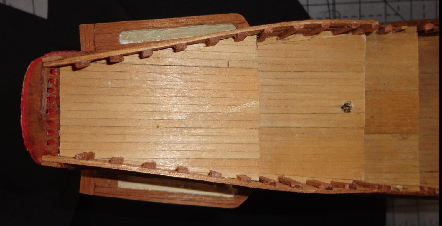
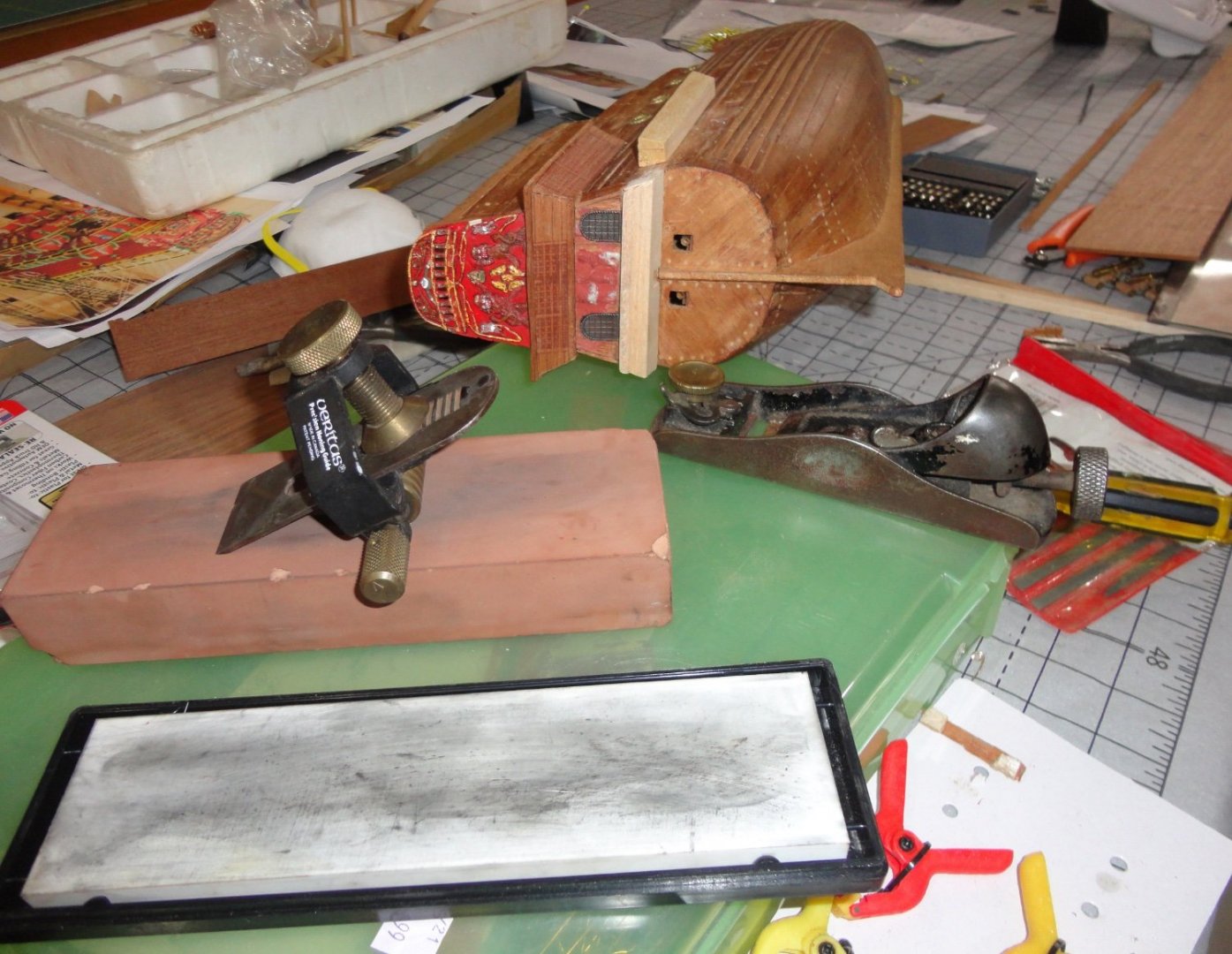
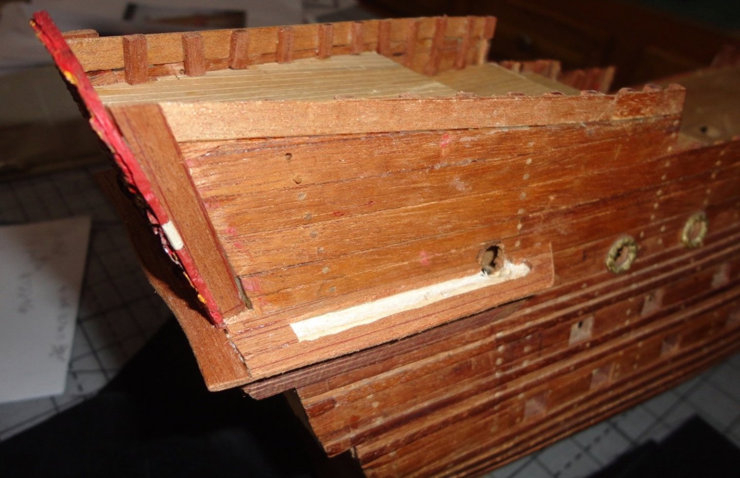
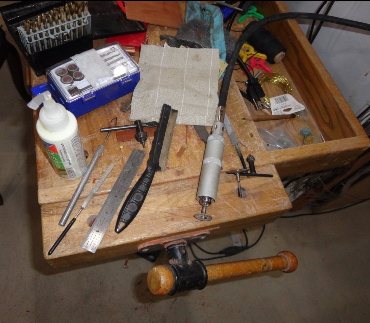
Thinking about the best grain orientation for re-sawing mahogany planking stock ... If one has a perfectly quarter sawn board (normally 3/4" thick in the U.S.) where the grain seen on the face runs parallel with the length of the board (one can always plane the edge to make that edge get parallel with the grain lines seen on the face), then cutting thin stock off the edge should provide the best bend-ability. The dots on the face of the planking are the 'rays' in the wood seen on-end. When cut at other angles, the rays present oblong to linear markings on the plank face. There are many books on woodworking and understanding grain, cutting stock, etc. Back to the model, I took a picture showing a number of things. Because the Cherub molding on the piece removed from the back broke, I glued the pieces to balsa substrate and made repairs her and there. I scrounged rear windows from another old kit I use for supplies, and realized that they should be recessed to become flush - since military miniature figures will have to be added later on either side of the windows. The rotary tool was used with a milling bit (hand held, I had to be extra careful not to remove too much material). Balsa pieces were glued below to provide the substrate for the lower gallery, and I used a low-angle plane to shave off the balsa on the stern - since the grain was oriented across. The blade had to be quite sharp, and you can see the Veritas holding jig to assure the bevel is even on the blade - which is on a Japanese water stone (here shown dry) 1200 'grit'. There is a tiny arrow on the end of the brass knurled cylinder if the sharpening jig that is shown pointing 'up' in the picture. When the bevel is cleaned-up, this arrow is positioned pointing 'down' (there are detents on the barrel of the jig) to create a 2 degree micro-bevel. The white stone at the bottom is a super- fine (6000 I think) finishing stone for the micro-bevel. Then the blade was remove and the back worked flat on the finishing stone. Stropping on a piece of thick leather was a final step in getting a razor sharp edge. Then the low-angle plane could shave off thin curls of wood going with the grain. I suppose that it could be used to taper planking as needed when doing planking. I've heard that miniature planes may be available. In the photo, you can see the side piece of wood I'm shaping before gluing to provide the substrate for the lower side gallery.
-
So very nice HakeZou ! - I will refer to your build (and others) when I get around to this project. I love the way you've put in decent steering tackle on deck astern. Your addition of hanks on the pin rails is practical and attractive. You have made great recommendations for enhancements, and one could add to them with: Install chainplate from the lower deadeyes to the hull; Use custom rigging rope made on a mini rope walk (done at home or purchased commercially) to limit 'fuzzies'; Copy the sails on finer material ... but even 'out of the box', Endurance is a fine intermediate kit. Fair sailing, mate ! Johnny
-
... A site I'll revisit as I cobble my old build into better conformity. Yours is looking good! Johnny
-
Metal bashing
Snug Harbor Johnny replied to michael mott's topic in Metal Work, Soldering and Metal Fittings
You are a machinist/builder par excellence ! My hat's off to you, sir. -
No picture in this post, mates - but comments on how I'm working with the mahogany - often found in older kits. Different stocks behave according to how the grain ran when cut. Thin veneers can spit, and planking stock can be weak in a certain direction where the grain runs. Handling the various pieces can reveal which are better to bend. The color van vary, but can be pretty closely matched. I'm talking about Honduran mahogany exclusively (there are other types like Philippine and African), and because of the present limitation on supply and high cost, one does not find find it much in new kits. It is most attractive for hulls that are mostly unpainted, since it does not need staining at all. The color can darken slowly with age, presumably to additional surface oxidation. It does not show glue from squeeze outs very much if aliphatic resin glues are used, and I find that excess can be scraped off in most cases. Because there will be no finish applied, the slight presence of dried glue is not an issue in my opinion. But if lighter woods are used that need finishing, any area affected by glue (not sanded away) will not take the stain and really show-up. I find that gaps or mistakes with mahogany can be remedied by fitting a suitable scrap and glueing for later re-cutting/sanding. The repairs blend well for the most part. Walnut is another dark wood needing no finish, and the same principles apply - except that wayward glue can show more on the darker walnut. Availability is good, for there are a number of species widely grown around the world. Perhaps working with colored woods on furniture projects over the years have endeared them to me.
-
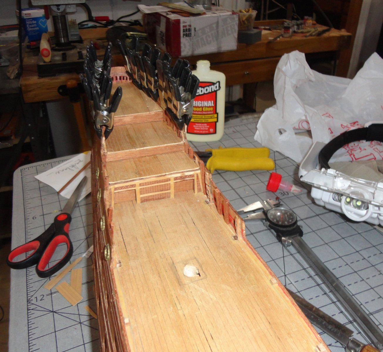
The next step was done on both sides - since someone looking closely (cringe) when the top part of the walkways are built will be able to see a little inside the 'gap' between the bottom and the top components, I decided to use a rotary tool to mill away some of the basswood/balsa underlayment where the walkway would be - as well as cut an access door in the side of the ship. I'll pain the light wood black, so it didn't have to be routed out very deeply, as the viewing gap (for any aboard to see out of) is relatively small, thus it restricts the angle that a human observer of the model will be able to peer inside. Below is a top view. A view from the side shows the little doorway cut into the hull. The wood across the stern was given a little undulation as seen on many models. There is a little improvising as each step is accomplished, since the alterations to the 'outdated' old kit have to be done without instructions ... but all the great builds and other museum information help in the process. And indeed, there are differences from model to model - as the finesse and detail seen on the original ship in Stockholm are challenging indeed.

-
Guterman thread is found (SE Pennsylvania, USA) in sewing or many quilt shops, and it has good strength in the sewing I've done. But I like Metrosene (made by Mettler - also a German company) even better. I'll try it for rope making - noting that the full-size demo rope I make at Colonial craft fairs on my hand-cranked gears rope walk has three strands of common jute cord on each of the three spinners that will make the three strands of the rope. When I get round to using the Rope Rocket (thankfully drill powered), the layup will be the same, as I haven't dabbled with any four strand rope (those using antique rope spinners with four hooks have that as an option). Different thickness of rope require different thicknesses of cord, and in the case of model ship rope that means different thread weight. The finest I can find is #80 in cotton, and it easy to break - but would make the thinnest rope, and would be reasonably strong once made from all the strands together. #60 and #40 will be progressively thicker. There are other weights going down to buttonhole twill.
-
'Love your furled sails ... something I want to do on a future project. Some of the blocks seen in your photos look like the Cutty/Thermie blocks in the Revell 1:96 classic kits. This is a good use of ready resources, and one I'm likely to make use of in time.
- 3,560 replies
-
- 1
-
-
- clipper
- hull model
- (and 2 more)
-
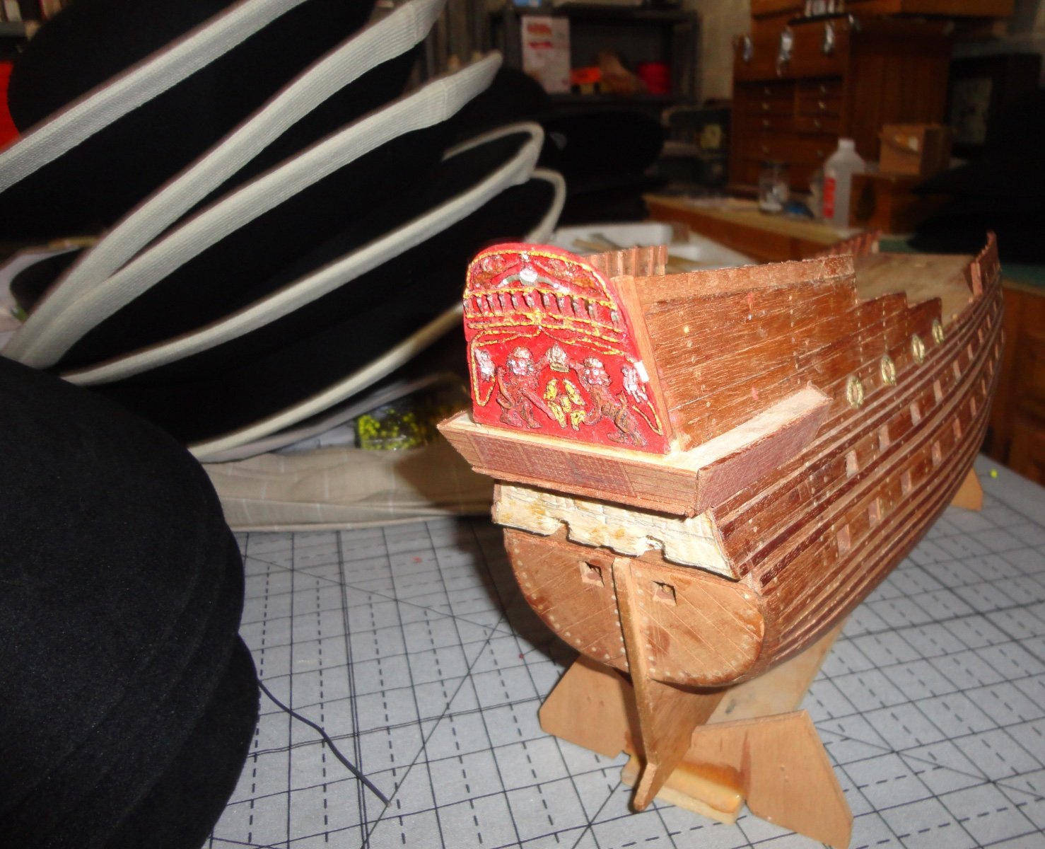
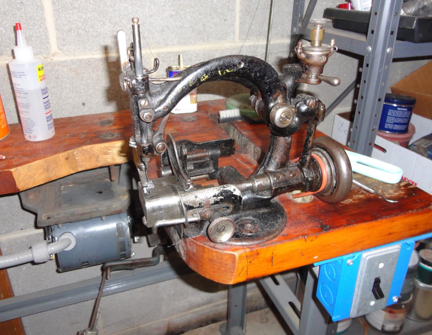
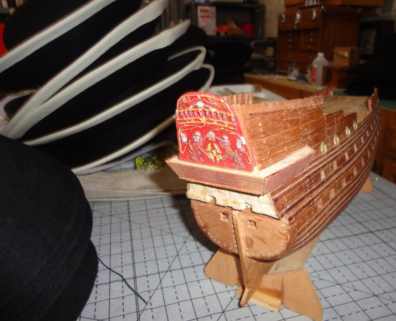
Ahoy! The angle-sliced basswood was saw trimmed (angled) as needed to glue on the sides as backers, then the 'blocky' balsa was sawed on the ends to match the angle of the new pieces. Knife cuts trimmed the stern angle on the balsa since it was with the grain, then I glued on some of the Billings scrap deck veneer and ... things are starting to take shape with the upper 'Captains Walk' - which will need a small gunwale and supports for the canopy that will have to be built. My interest is indeed renewed since gaining new inspiration through our forum (a shout-out to all who contribute) and I understand better the words of Einar Billing provided with his kit: "... this kit is intended to be built, and not merely assembled, in consequence, you must not expect the parts to fit together perfectly ," (no exaggeration there !) "it will be necessary to exercise skill and imagination in the building of this kit ... after all, any child could put a puzzle together." You may notice some black felt round hats piled on the table ... The Admiral is a costumer, and she also accepts orders from a purveyor of American Revolutionary War re-enactment goods for Colonial soldiers hats. I am the unpaid hatter who has to craft the hats from materials provided by the retailer - which involves cutting and sewing and installing draw-string hat liners to felt hat blanks, sewing worsted wool trim around the edge, making tasseled hat cords plus cockades. The retailer does the heat sizing and turns them into 'three cornered' hats. This rush order for 25 hats slows down progress on the model ... its my job to say 'Aye aye' to orders. Below is an image of my trusty Wilcox and Gibbs hat band sewing machine (well over 100 years old), which took me over a year to find - and even then I had to rebuild the stand, rewire the motor and recondition/adjust the machine to get it to work (finding specialty needles and grinding to suit was a challenge), then figure out how not to keep breaking needles. Once mastered, it took 90% of the work out of that part of the job ... and the old girl is quite solid and made entirely of durable alloy steel needing only a little oil now and then. For trim work and accessories I use an old Kenmore that I modified, and the drive works happen to be all metal in a plastic shell. As Louisa May Alcott (1832 - 1880) said, "I am not afraid of storms, for I am learning to sail my own ship."

-
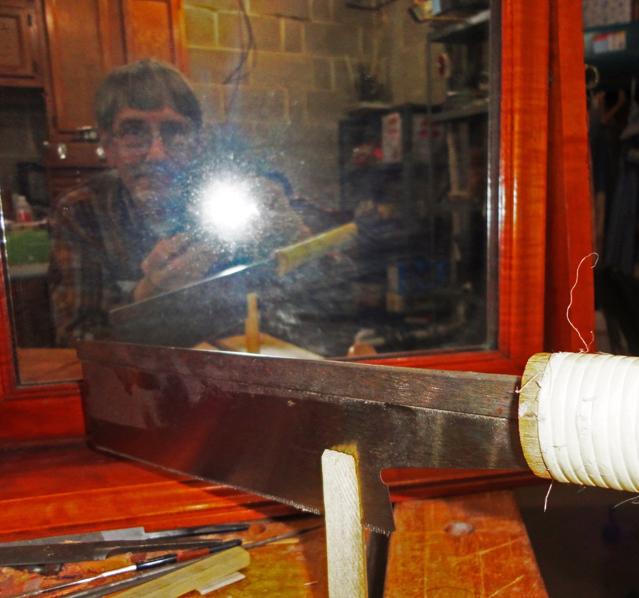
I understand that the name now is Vasa - but I'm not sure if I should change the title of this build. Anyway, I realized I had to cut into the stern a little more, than start gluing some balsa to be a backer for planking the upper gallery and stern wrap-around. Yes, balsa is not a great wood where it will show - and the relative softness of balsa stock can vary widely. The 'firmer' sort can be used a filler, backer and in a variety of ways - yet it still cuts easily with hobby knives. The image below shows step one. Once shaped and planked, it should look a lot better. I need to glue wedge-shaped side pieces for the lower part of the gallery, so I started to saw a suitable piece of basswood stock (better to use than balsa) with a Japanese dosuki saw. This is a 'pull' saw with a thin blade and narrow kerf - it allows pretty good control as long as one does not let the blade 'wander'. I tried a 'selfie' shot using a mirror, but the flash made a bright spot and I'm a rank beginner when it comes to Photoshop. The saw in mid cut on the basswood stock shows OK. Hmmm, it might be said here that the artist is no Botticelli - and the subject no Venus.


-
Hake, thats amazing! Watching the second boat from the front carefully - one can see that as the forward davit pivots inward, the prow of the life boat moves back enough to clear the davit ... and take note - while this is happening the rear davit tilts just a little toward the stern to accommodate the rearward motion of the boat. The forward davit continues to pivot (probably winched by a man at the davit - while the rear davit may be allowed to adjust itself freely by releasing a clutch ... or actively winched by another crewman). So the prow of the launch will clear the forward davit and as that davit continues to pivot fully out board, the rear davit just 'comes along' - perhaps assisted by engaging a winch for the outbound portion if its travel. That's a LONG way down from the deck of the ocean liner, and I noticed that some of the boats start tilting at what might seem an 'uncomfortable' angle due to the tackle on the ends being cranked down at different rates! Of course, somebody would be watching for this (perhaps prompted by yelling from below) and adjustments could be made to bring the affected lifeboat back to an even keel. Practice would improve performance. Now imagine doing this at night on the Titanic ... going slowly down by the bow ... in freezing cold and with scared people in the boats. Fair sailing! Johnny
-
'Just the engineer in me pondering how the launching process would go for those lifeboats stowed on the racks, since the distance between the davits is less than the length of the boat end-to-end. Maybe something like raising the boat, and then manhandling one end to get around the davit on that side somehow - then pivoting that davit to face outward. Then the second end would be easier to 'get around' the remaining davit before turning the second davit seaward.
-
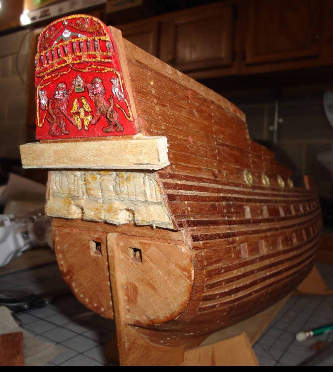
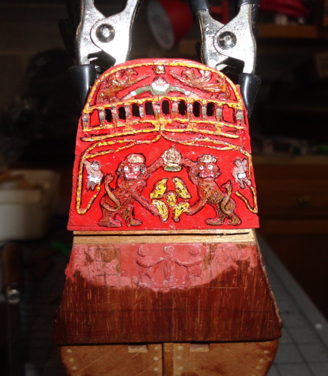
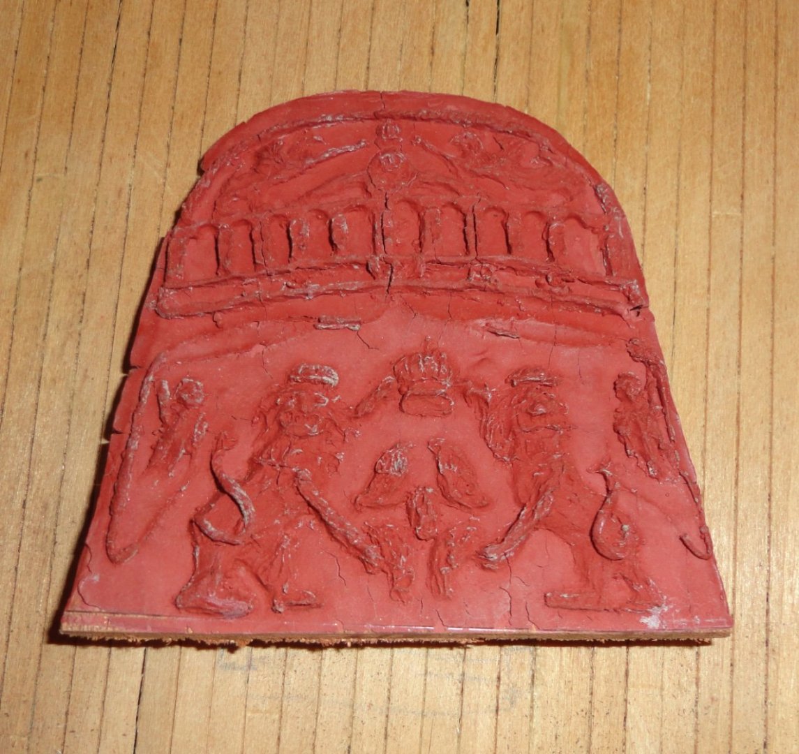
'Been a couple days, but there has been some progress. The first pic shows additional side planking being added to the stern. Before that, the 'three level' arrangement of decking was made - there middle level had a piece of balsa glued in and planked over ... not by individual planks, but by some scrap that was left of pre-scored birch (a guess) veneer from 40 years ago. I wonder if something like this is still available, 'cause it sure makes decking a snap ! There are just too many things that 'aren't made anymore' these days. Just as with the additional bulwarking needed up front, false ribs of mahogany were glued to whatever planking showed above the deck - and the little clamps pictured (bought at a Woodcraft store) are dandy to hold them fast while the titebond cures. I make them a little longer than needed, since they'll be trimmed later with a rotary tool. I like working with mahogany - just orient the grain as needed for the use and cut with the grain or saw against. Because it has natural color it doesn't need staining. With ribs in place, a side plank is added and the same clamps are used to hold. The stern panel (just seen on the inside) was trimmed and pierced (rotary stool to make holes, and mini files used to shape and clean), a piece of basswood was a spacer. There are no 'plans' per se at this stage - just photos from other builds to give me ideas. As previously mentioned, I'm free to take a few liberties in converting this old kit version to something better resembling the original ship. And I imagine that someone who had seen the ship being built (or sinking) back in the day might have desired to build a model after the fact (as was often the case) and had to rely on their memory. Very old ship models have a certain charm, and I agree that in restoring an antique model the best policy is to stay with how the builder made it - as opposed to making a lot of augmentations. Exception: the build of 'My Father's Ship' (Cutty Sark) is a labor of love to finish what was started in a legacy situation. I compare this 'free style' assembly perhaps to rock climbing. I have to look at it and decide what the next move will be. How do I get from 'point A to point B' - and what are the intermediate moves I have to make to get there. The next shot is of the re-mounted stern piece that I thought would be better if I painted it FIRST while still a separate piece. I used good-old Testors model paint (enamel) that comes in the tiny square bottles. I recall them seeming much bigger from when I was a kid, but my hands have grown to twice the size they were back then. My dexterity is not near as good, but my hands are still fairly steady - and the magnifying headgear makes up for the lack of close focus on my replacement eye lenses (from cataract surgery). I considered getting the close-up (reading) replacement lenses, but then I'd be dependent on glass for distance. So I got fixed distant lenses put in so if my Varilux glasses are misplaced, I can still drive without glass since the distance is sharp. As noted before, I used modeling clay on a piece of glass to get something resembling the wood carvings at 1:100 scale, then layered on latex compound (I hope one can still get that somewhere) to cover the sculpture. Dental plaster was used to make a back support of the latex mold before it was stripped away from the glass. Using drying clay might make cleaning out the rubber mold easier. Then some plastic wood was slathered on the mold before applying to the wood for the back piece. Cutting into the model took some guts, but once decided upon was done in a surgical manner ... not unlike a ship's doctor having to do amputations after a sea battle, or saving what he could while stitching up, etc. In this case the 'patient' (my model) was in no pain. The red background was applied first (mixing two colors to get the shade I wanted), then the other colors added to the higher reliefs with very small plastic applicators found at the hobby store. The polychrome effect is certainly nice - as we now know it to have been on the original. Application of gold leaf was kept to a minimum on the Wasa, but I used gold paint for the crowns, and little dots of gold over the yellow painted bits. Painting eyes on the figures really brought them 'to life', and the whites were applied by the tip of a mini round tapered file. The black pupils had to be dotted with a fine 'technical pen' (oo5 Micron pen bought at Michael's craft store). But the cherubs and the King's eyes were small enough that the pupil had to be applied with the tip of a sewing pin. Then I outlined the decorations in black with the technical pen - a technique used on illuminated manuscripts called 'limning' - which sets everything off nicely. This close-up magnifies the imperfections, but the appearance when just looking at the piece is pleasing. If this project inspires me to do another Wasa at the scale presently offered (1:70 ?), I wonder what the opinions are of the kits presently offered in terms of pros and cons about the quality of fittings, accuracy of plans and quality of instructions ? Any input would be appreciated - after all, this is a forum. I can't say what a pleasure it has been to review so many great builds at all skill levels available. Its like a primer, and one can find all kinds of helpful tips and tricks. The latest one I saw was an example of deck planking where after a plank is laid, a piece of black thread is put against the plank before butting the next plank against it - sort of like imitating real caulking. Fair sailing, Johnny


-
'Ever complete the Grand Prix car? I have the kit and intend to have a go at it eventually. I did build the Hurdy Gurdy and to make it work half good, there had to be MAJOR modifications, Wood-on-wood 'moving' faces were sealed with model airplane dope and sanded smooth with super-fine sandpaper. Then there could be a little PTFE model train lube added to reduce friction and noise.
Some of the journals had mini ball bearings installed (these were large enough to do that, but the car project is too small). I thinned the soundboard on places, enlarged the sound chamber and installed spring returns for the keys. With real instrument strings used its not half bad but ... I had fun doing it, staining the outside and varnishing. Looks wonderful.
So when I do the car its going to have to be done with enough care to make it operable (some builders have had troubles). Johnny
-

Nope. The Admiral insisted on parking her car in MY man cave! Rude, right? No priorities. Sold a 69 GTO and gave away the lift used for the off chases restore. JUST finished today moving my model workshop to a spare bedroom. 10'X10'. I was just getting ready to post pics in the "What have you done today" topic.
Lost too many parts in the move including major parts to my serving machine made by <SP?> Alexa Dominnov. I had version 2.5 and He's now at version 4 so I didn't mind getting a new one.
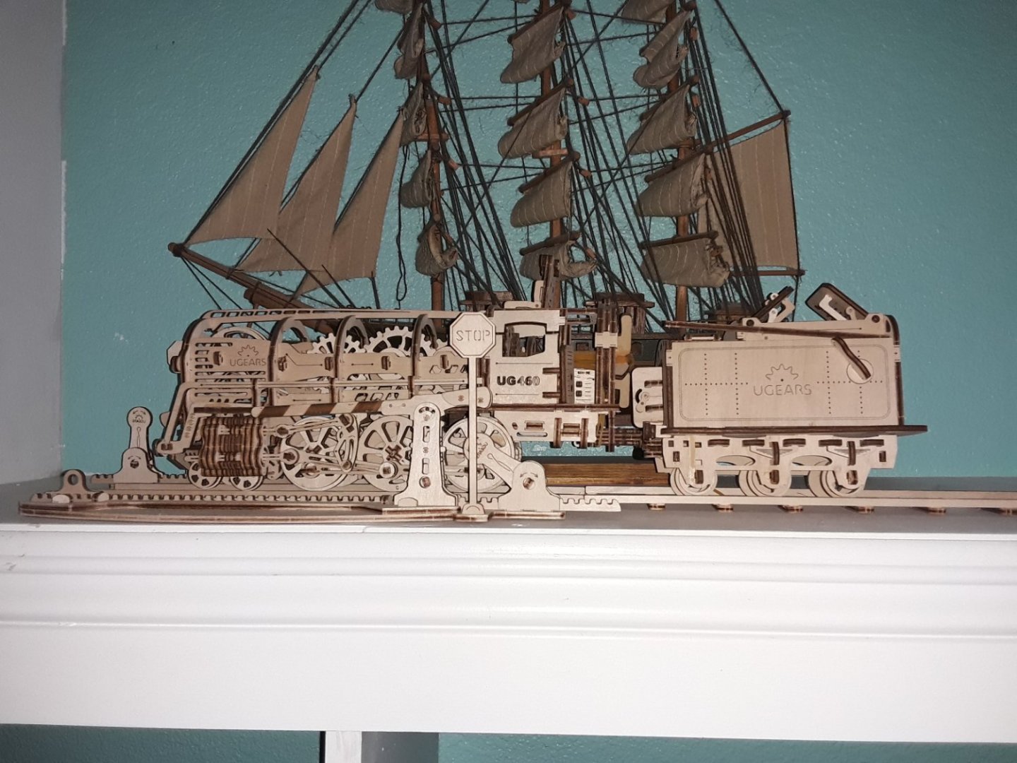
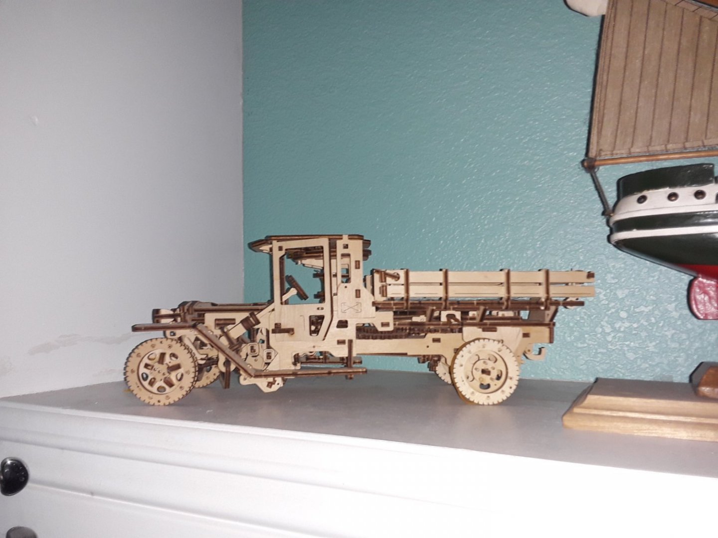
I did these a few years ago. They both work but the truck was supposed to have dualies and I just couldn't get the second set on.
Thanks for asking, though:)
-
Admirals ... gotta love 'em ! Fair sailing, mate. Johnny
-
-
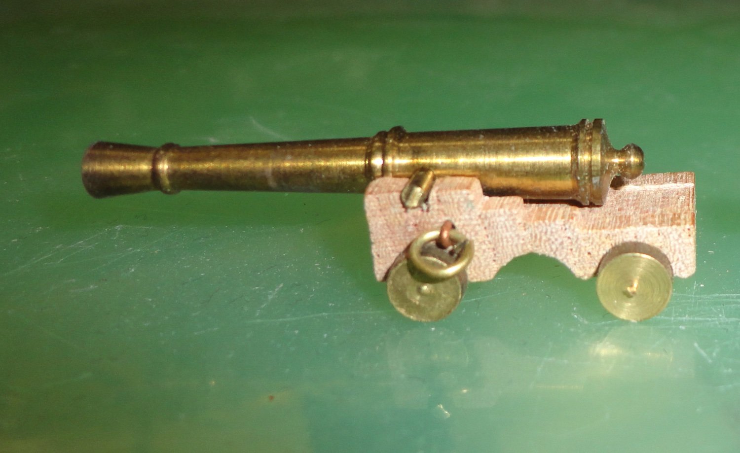
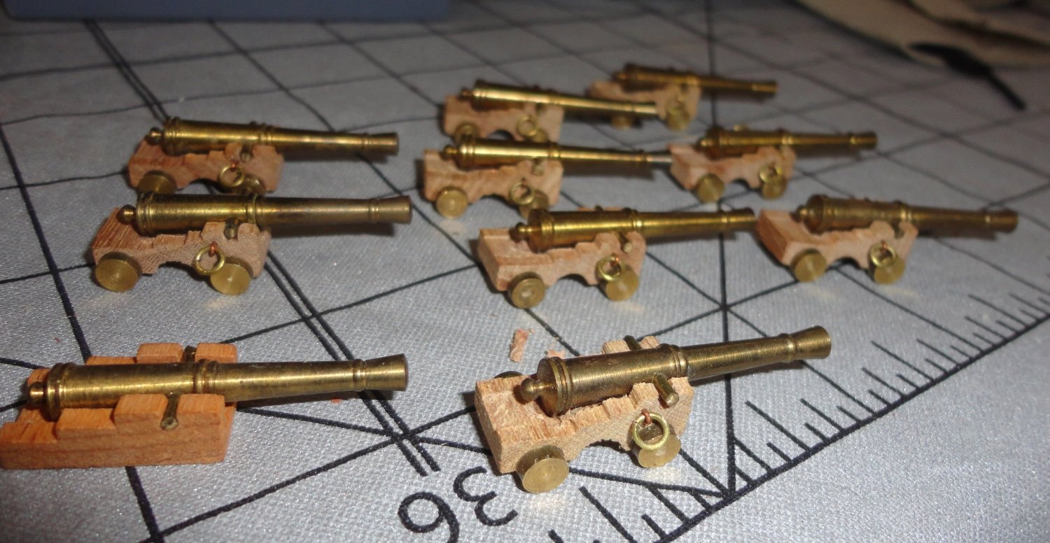
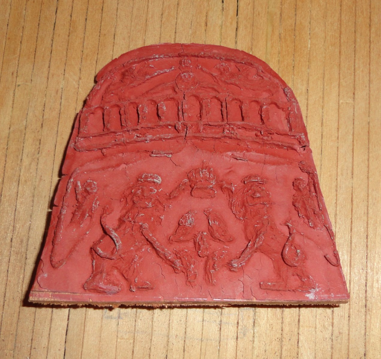
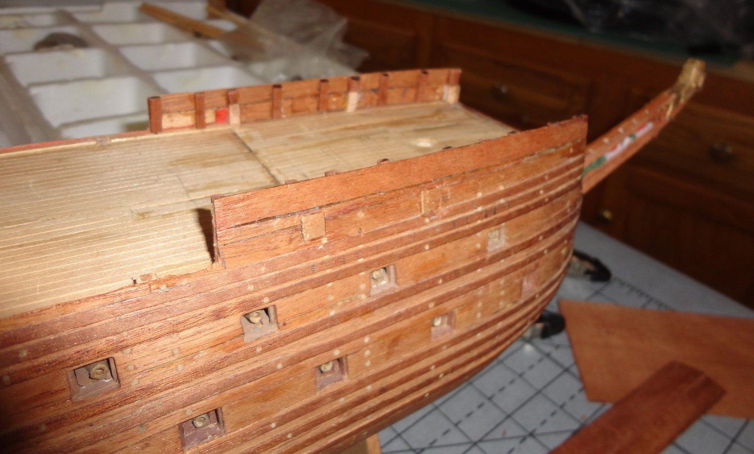
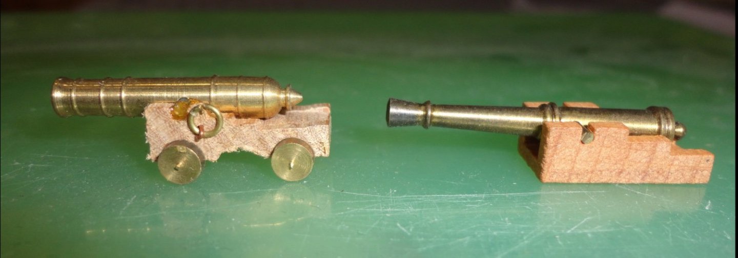
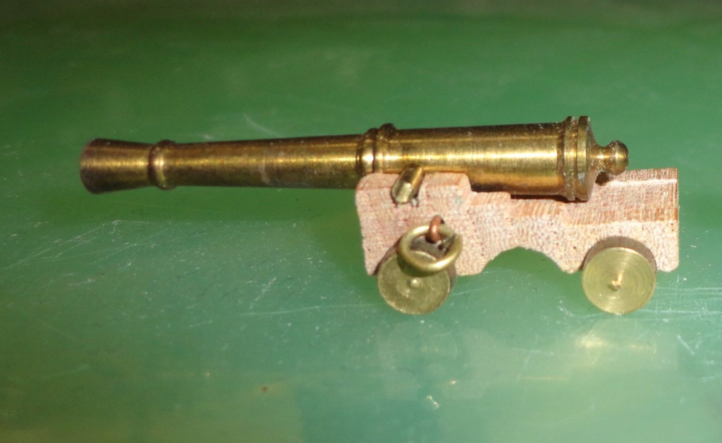
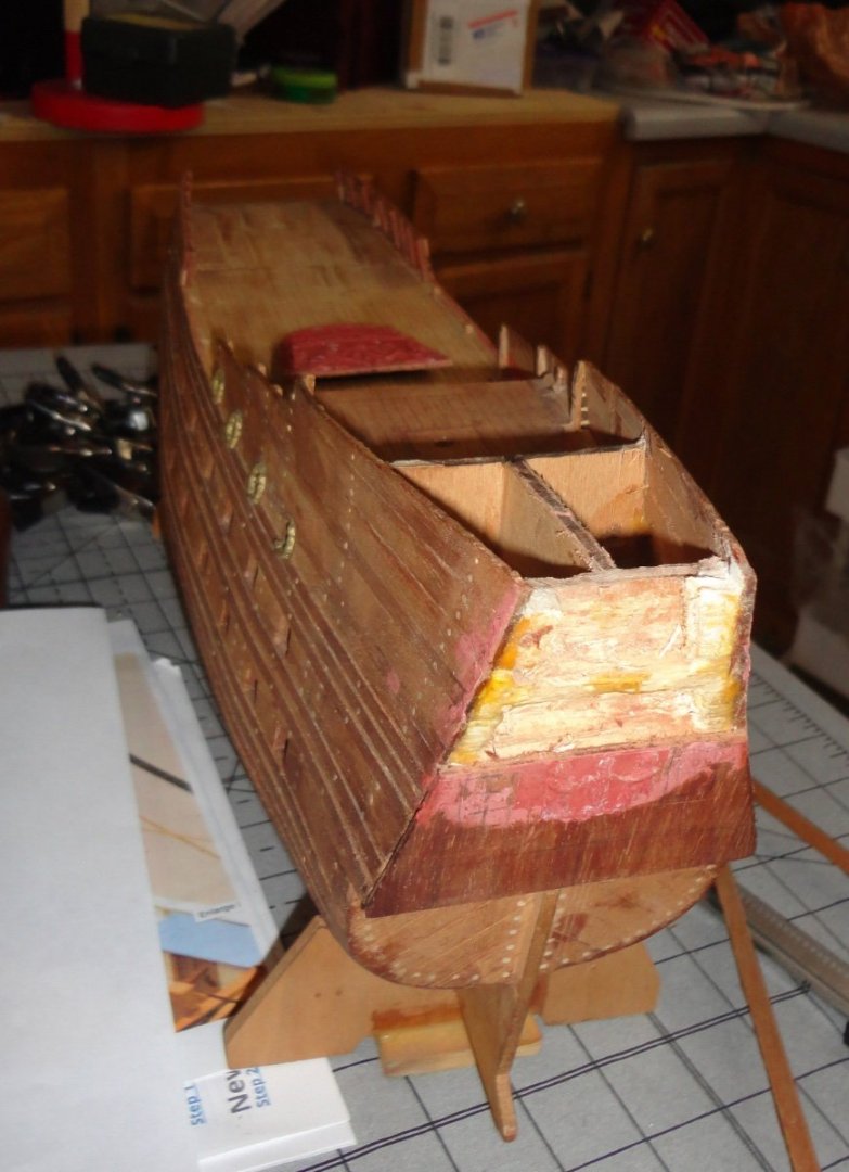
Ahoy mates ! (there's been a long hiatus on this build) After thinking a lot (yea - the Admiral said, "You've been thinking? I thought I smelled wood burning.") I've finally decided where I want to go with it. First off, a review of whats was 'wrong' with the first-issue Billings kit (actually a lack of all the information we have now following decades of recovery and restoration) that are likely not correctible. Billings is a good company and they have improve kits where needed. Which this old version, the lines are off, gun port placement off, the plank scale much too large, the cannons approximate but all of the same type, deck layout conjectural ... I'll stop there. So why go to great lengths to try and make masting/rigging kosher when the hull (with some corrections) will still be 'standoff scale' ? That is - something that will be recognized as the Wasa at first glance - but still not up to snuff when closely compared to the prototype in Sweden. Another option would be to be liberal with the masting/rigging (shortcuts and approximations, I mean) ... to go with the hull. There is a lot of work already invested in the hull, and it doesn't look half bad as is. Hmmm, but I'm taking option 3, which is to install the first section of masts and adding shrouds/ratlines like one can see on exhibit at the Wasa museum. This would represent the ship still under construction. I note that she was never under 'full sail' - just three on her disastrous 'maiden voyage'. To keep dust to a minimum, a display case has been recommended - plexiglass to lessen the risk of breaking window glass, so therefore the case size will bess daunting as well as more portable - so a greater chance that a relative might want to have it when I'm gone. I've always been a 'hammer and chisel' guy, and a jack of all trades - many projects (an outside deck, two kitchens plus several bathrooms over the years, a greenhouse, three scratch-built telescopes, sundry models, historic costumes, three harpsichords, bookbinding, candle making, several muzzle loaders - to name a few) have been useable, but the quality of work far less than 'craftsman' level. No worries mate, I only have to please myself - and its the 'doing' (and preceding that the 'thinking out' stage) that is the interesting part - dare I say 'fun'? The picture below shows a gun taken from an old Steingraeber 'Fair American' kit (harvested for parts, etc. since there are better more recent kits available) and the gun looks a little 'fat' for the carriage. On the right is the gun from the Billing accessory kit (for the 1:100 scale model), where the barrel seems alright for my purposes - but the carriage is simple and would need more work to upgrade. So it hit me that I might put the Wasa gun on the better carriage and - shazam - look OK to me. Now I'll have to tweak things a bit, add straps over the trunnions, wedge and whatnot - then change some of the gun port heights and they'll be serviceable. Below are more of the guns to be seen on the weather deck. Now to some more 'surgery' on the hull. It was with great trepidation that I sawed across the stern piece (glued-on many years ago). I feared that the applied 'plastic wood' (pressed by a mold I made of the stern decoration) might come off, but it seems to have enough 'grab' to be stable. Remember, all this gets painted in polychrome like the original. I cut the glue around the periphery with an X-acto, then pried with a flat chisel from the top and ... POP ... off came the piece, revealing some balsa underneath put in as a spacer. Thank goodness that balsa has far less strength than hardwoods. I have to make the high stern decks into 3 tiers, rather than the two that were on the model. Using a flex-shaft variable speed tool was very helpful in a number of areas. The only thing better would be an old-fashioned dental drill with right angle head. Below is the piece I removed, and it is a close enough approximation of the upper part of the stern decoration. Note that the old kit did not have ANY of the many sculpture carved on the original ship ... so the later kits are a real advantage to any modeler. To change the forecastle area of the ship, false ribs were cut from mahogany stock and glued into place (titebond), before additional planking was added to get the height desired. I believe the original was designed to have a forecastle deck, but after unreasonable design changes were demanded from authorities many at the build site knew there would be stability problems - what, with 30 added feet of length and an additional gun deck! So instead of adding the weight of framing and decking (plus additional armaments), the builders left that area open. Look at pictures from before, during and after 1628 and you will see forecastle decks everywhere. The absence of one (confirmed by the restoration of the original) shows the Wasa to be an exception to the 'norm'. I'll offer a view of part of my work area - disheveled as it is - to show some of the tools I use most often. You can see the flex-shat rotary tool (yup, Harbor Freight) that is better than a stock Dremel due to the foot operated speed control. I also have (not shown) the mini saw (another cheapie) for trimming stock. I think a better mini table saw will be a better investment. I use a model railroading 'track cutter' (so-called 'snap' saw) for cutting off. Needle files of various shapes (including bent 'riffler' files) are invaluable, as is the 'good old' X-acto knife. Straight edge, pencils, titebond glue (aliphatic resin) augmented sometimes by fast cure epoxy (I have yet to make use of CA, but will try some in future) mini-clamps and, of course, sandpaper of various grits round-out the tool kit. When I have more to show, I'll add progress pics. Fair sailing! Johnny


-
How far could a ship of the line travel?
Snug Harbor Johnny replied to Admiral Beez's topic in Nautical/Naval History
Without enough vitamin C, survey among the crew was a problem until the British navy took up the suggestion for the mandatory consumption of limes ... hence the term Limie (alt. Lyme). -
I'll apologize in advance, but I wonder if anyone in the forum has ever tried putting sandpaper on a vibrator to fair planking ... just a crazy idea. I mean, it could do well for the inside curves below the stern, but I'm not sure whether I dare ask the Admiral if she has one handy.
-
I recall reading that Scott pressured Schakleton to promise not to use Scotts abandoned shelter prior to Schakleton's attempt to be the first to the Southern Pole. The time spent unsuccessfully looking for a landing meant that Scotts works were used anyway, but not enough depots could be laid before winter set in (if I recall correctly). The promise should have been 'qualified' (safety of the crew first, you know), and if Shackleton had occupied the abandoned works sooner, he may well have laid the depots needed to be first to the pole. Hmmmm, dogs would have helped a lot regardless, but one may recall the 'mindset' of dong it by human effort alone. Amundson was a better planner and a more practical man.
-
Ahoy Rob ! With your project there's been a lot of work done already - and the Billings kit (although not the current one) is definitely an improvement over the 'original' version issued in the late 60s ... the one whose hull I built back then and recently have re-started the work in light of present-day knowledge. I'll soon be adding a couple of images to my build dealing with corrective issues - such as they are. The lines on your version are much better, and the fittings in the box are more extensive. As far as the gun ports are concerned, somehow I had the vision as a 14-year old to cut the ports in the planking before any decking was installed - then I glued pieces of 'false decking' on the inside of the hull below the holes. Dummy carriages were made of balsa and dowel pieces (with one end drilled to accept the half cannons) representing the back end of the canon were glued in the dummy carriages. Balsa strips were glued around the inside of the square holes in the planking and tinted brown. The effect is pleasing seen from the outside. Fair sailing! Johnny
-
Hey Rob, when done with the Glory (and a glorious project she is) - how 'bout trying a bigger clipper ... the Preussen (1902) with 5 masts and a hull over over 430 feet and more than a 50 foot beam. 😉 Today is a 'red letter' day for my Wasa project (dormant since March of last year). So many things have been done on the Admiral's 'honey do' list (and Winter precludes anything outside), so I just 'up and started'. Now there was much to think about in the intervening months, and think/research I did. I concluded that there was so many inaccuracies in the late 60s 1:100 Billings kit partially done (due to far less being KNOWN then), a 'standoff scale' approach is appropriate without worrying too much about what is off from the prototype - and there is much I can do to correct some key things. I'll focus on the hull appearance and just put in the first sections of masts (like in the museum) to represent her still under construction. After all, she didn't get very far with only three sails set before sinking on her maiden voyage. Wood is a fairly forgiving medium, and all I had to do was start cutting and gluing in a logical order to start making more corrections. The 'Harbor Fright' mini table saw was acceptable (although there is no fence - so a clamped piece of wood had to do) once I installed a much higher tooth-count and thinner blade I was able to find with a 1/2" arbor hole (not easily located). Discovering that the arbor threads were reversed helped - 'leftie loosie' did not work, it turned out to be righty loosie! Slow and steady she goes. Johnny
- 3,560 replies
-
- 1
-
-
- clipper
- hull model
- (and 2 more)
-
Incidentally, Marx 'scale tinplate' has S gauge bodies on O gauge trucks. This is why some S scale train operators drill out the trucks of Marx rolling stock and replace them with S scale trucks. Great idea for figures, and I found a hobby store with 'old' stock figures in several sizes ... such stores are still 'here and there' but growing fewer as the years pass. 'Just viewed 'Master and Commander' again on cable streaming ... good to see once in a while. Now there was a flogging in the film (not uncommon in the British Navy back in the day), and I wonder if anyone put figures on a sailing ship model representing such a punishment witnessed by the crew (standard procedure).
-
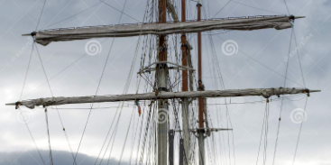
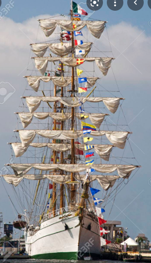
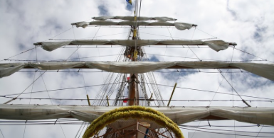
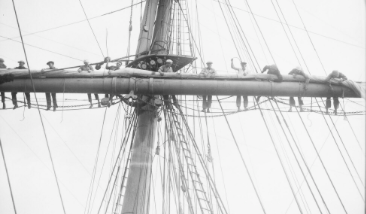
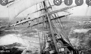
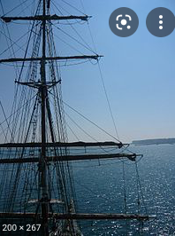
Ahoy Bruma ! I'm not finding the furled sail pictures I recall seeing, but did see another forum-posted approach by Lubber that could be made a little less 'bunchy' by using a narrower strip (from side to side). So I 'Googled' "furled sails" and found a few shots for educational purposes - The first one has the 'compactness' that I've seen a number of times. Note that these are photographs of ships versus artist's pictures - there are many examples of contemporary and 'period' (typically engraved) representations of all sorts of sails in all weather. The photos also show several appearances : The first is once and compact, yet the second has a 'festooned' appearance (perhaps for show) where the sail cloth looks like bunting across a stage (the origin of bunt lines?). Another shows more prominent hanging 'ears', and there are a couple of old shots of men working the yard ... the one at sea in sort-of rough conditions makes one think how challenging life at sea under sail can be.
- 399 replies
-
- 4
-
-

-
- cutty sark
- revell
- (and 2 more)