

Gregory
-
Posts
2,694 -
Joined
-
Last visited
Content Type
Profiles
Forums
Gallery
Events
Posts posted by Gregory
-
-
-
-
-
You may have already been there, but in the Gallery under “Contemporary Models “, page 2, there are several cutter models. You might get some different ideas about companion ways.
- mtaylor, iMustBeCrazy and oakheart
-
 3
3
-
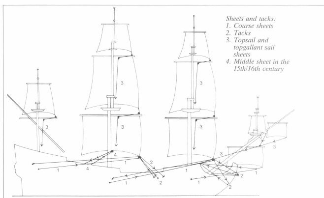
There is not a simple answer to your question, and that is a very simplified rigging diagram.
It is difficult for me to tell which line/s are represented by your green highlights.
They might be the sheet lines that would be attached to the lower corner of the sail ( not the middle of the yard ) and go through a series of blocks to be tied off/belayed on the deck or higher up in the rigging.
There are lines to control the yards and lines to control the sails. Some do a little of each.
The best starting advise you could get would come from a book such as Historic Ship Models by by Wolfram zu Mondfeld.
It has some very good rigging details, such as:
There will be help from many here, but the best help you will get is pointing you to the resources where this information can be found.
Another good rigging resource for beginners is Rigging Period Ship Models by Lennarth Petersson.
It provides a point to point guide for every line on the ship..
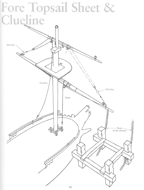
Petersson diagrams every line on the model like this.
Hope this helps.
-
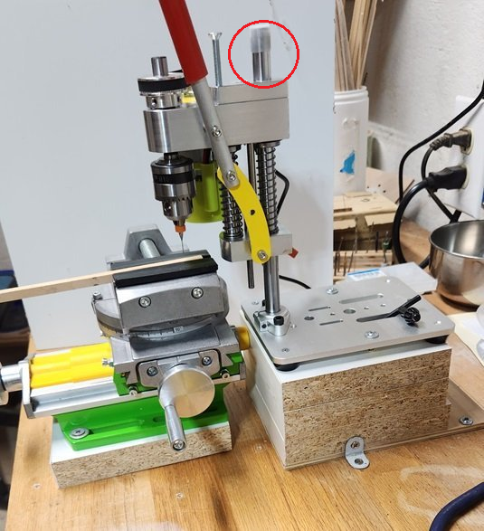
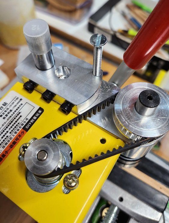
Here's with the new 12.2" ( 310mm ) rod installed.
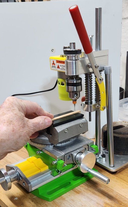
I set the old one there for compare. The rod from Amazon is very good quality and a perfect 12mm fit.
I set the height for the micro bit, but there is plenty of room for longer tools.
I don't have anything screwed down yet, but it will be a nice fit for my limited workspace.
Here is a rundown of basic cost.
Time will tell if it is good for the work to be done. I look forward to working with it.
- Chuck Seiler, Canute, kgstakes and 3 others
-
6
-
-
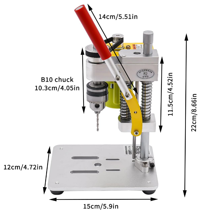
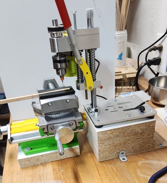
Take a look at the dimensions early in the thread. It has a really small footprint..
Here's a repost since we are on page 3 now..
- Chuck Seiler, mtaylor and Canute
-
3
-
4 hours ago, kgstakes said:
Would you say it is way better than a dremel tool in their drill press stand?
I think it's going to be better for me. Time will tell.
- kgstakes, Chuck Seiler, Canute and 1 other
-
4
-
-
-
-
14 minutes ago, kgstakes said:
Chuck is that post solid or hollow? If hollow you need a hacksaw hand drill and some bolts. No special tools needed.
How would that solve the problem of the bearings made for a 12mm post?
- Chuck Seiler, mtaylor and Canute
-
3
-
-
-
-
-
9 hours ago, grsjax said:
Specs said the shaft turned in a brass sleeve.
I can't seem to find anything about a brass sleeve in this particular one.
The one that Ron Burns posted about, and got me started on this does talk about a brass spindle and sleeve..
- mtaylor, Canute and Chuck Seiler
-
3
-
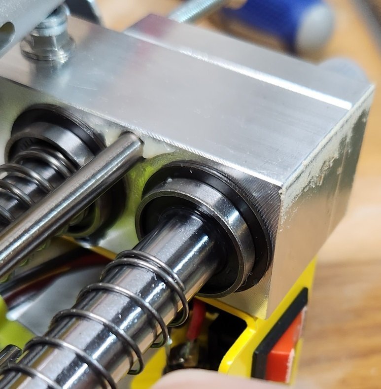
There is a bearing with a very tight fit, so I think 12.9 could be a problem.
- Chuck Seiler, Canute and mtaylor
-
3
-
2 hours ago, Chuck Seiler said:
Were you able to determine if the vertical post could be removed/replaced?
Definitely, now that you asked.
Want to kick me now, or later?
I could have got almost 2" of elevation by removing that plastic cap and moving the head up on the post.
There are scads of 12mm chrome rods at Amazon.
Here is a 23" for $18.99. A 12" would do it for my purposes..
Edit: Now I see you can choose from 200 to 1000mm.
Standby for super mini drill V2.0
Forget you saw that melamine crap, and thanks for the wake-up call.
-
40 minutes ago, grsjax said:
Should be ok for light work
It's not really intended for anything but light work.
The head moves up and down as smooth as can be. The spindle and motor are very quiet. I believe the spindle uses some type of roller or ball bearings.
Is their any way to tell without taking it apart?
- Chuck Seiler, Canute and mtaylor
-
3
-
Well, the mini drill press is a little more of a beast now.
I used some scrap melamine to elevate the drill and the X-Y table a net of a little over 2 inches.
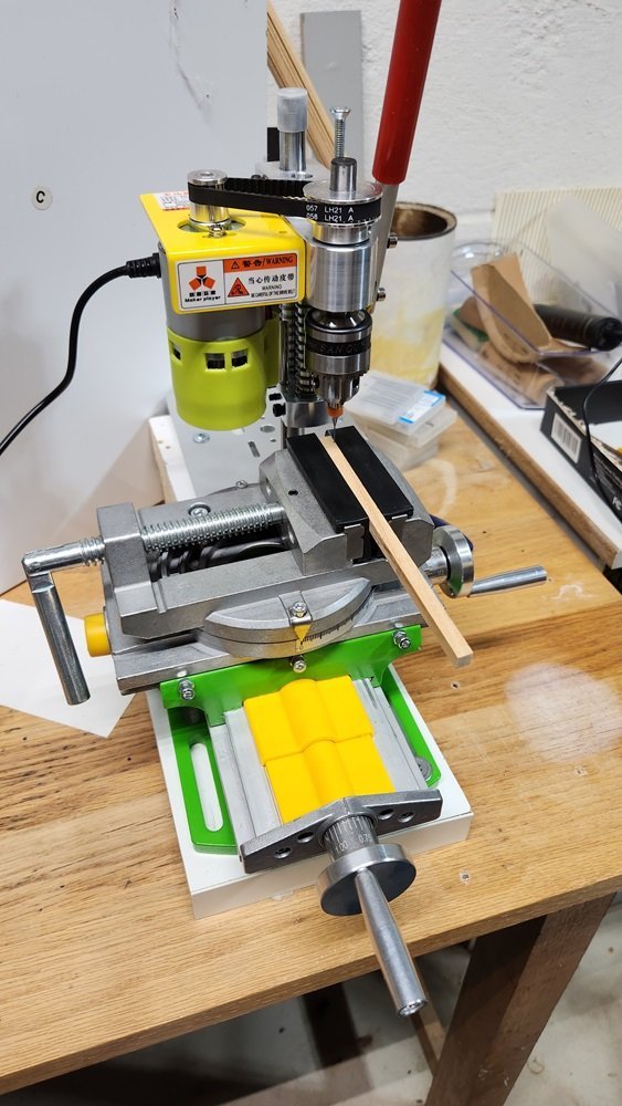
The little X-Y table is surprisingly well made considering the price. It seems very stable but doesn't have the precision that serious milling would require.
I could have done without the rotary table, but it will add a little more versatility should the need arise.
They do have a similar table on amazon without the rotary function at essentially the same price..
I discovered that the fixed part of the head has a threaded hole with which you can use a screw to fix the Z depth for milling.
I don't really have any jobs to do right now, but I feel like I have my micro drilling needs well covered as they come up.
I will do my best to answer any questions or try your suggestions.
It wouldn't surprise me if some of you could come up with a little more sophisticated configuration than I have managed.
- JpR62, Thukydides, Canute and 2 others
-
5
-
1 hour ago, Snug Harbor Johnny said:
Looking at this rig, what the problem might be is that the planetary gears that turn the spools don't twist enough in relation to the revolutions of the large disc laying the strands on the other side (not quite sure what the exact ratio needs to be).
I mentioned earlier that there is apparently something lacking in the tightness of the lay .
The Rope Rocket and the Frolic style rope makers twist the strands hundreds if not thousands of times to create the tension that causes the rope to form.
The Domanoff machine doesn't appear to be twisting the strands more than a few tens of revolutions. Perhaps someone with more knowledge could give a more precise number.
- modeller_masa and mtaylor
-
2
-
I Have a full sized house brand drill press outside in my workshop where my other full sized tools are.
I don't want to take my model work outside, bring my full sized tools into my relatively small modeling area, nor re-configure my full sized tools to work on a one-off modeling project.
Still, I guess it remains an option.
- Thukydides, oakheart, mtaylor and 1 other
-
4


Mini Bench Drill Press
in Modeling tools and Workshop Equipment
Posted · Edited by Gregory
What do you mean by " preciseness " in a vise ?