
Gregory
-
Posts
2,694 -
Joined
-
Last visited
Content Type
Profiles
Forums
Gallery
Events
Posts posted by Gregory
-
-
Thanks Glenn. Always glad to know you are watching. I continue to be inspired by your craftsmanship.
Thanks to everyone for the 'Likes' . I appreciate everyone who is looking over my shoulder.
- glbarlow, Dave_E, scrubbyj427 and 1 other
-
 4
4
-
1 hour ago, Diver said:
I took 2 short pieces of the planking, glued them together with CA.
Do you have a picture? Trying to understand what you mean by gluing the planking together. Are you saying gluing the planks onto the frames?
What type of CA? Medium consistency or gel should work.
-
Long time no update but I haven't been idle.. Sidetracked on a couple of other projects, and being less satisfied with how the hull is shaping up. I will have more on that later.
They say " The Devil is in The Details ", and boy, is it. In any event it all has to be done sooner or later.
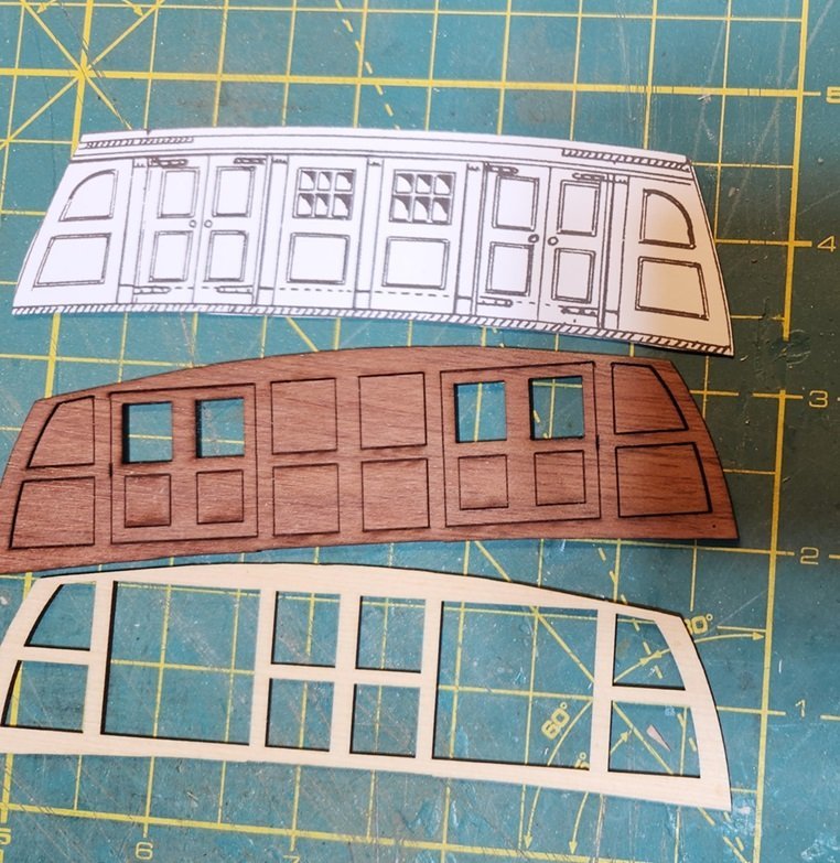
I discussed the design of the quarterdeck bulkhead a while back. As discussed, the drawing in the MS plans by Campbell is his ( expert? ) interpretation, and essentially duplicated by Hahn and Mamoli. No expert here, but I find the windows in the center panels and not the doors a bit incongruous. I made a back piece with etching on it and a frame to fit over the back, in which I was thinking about inserting panels and doors.
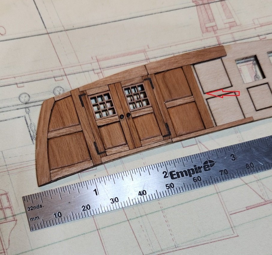
Going forward with a prototype, I decided to try some laser assisted carpentry. I don't want to paint, but going with bare wood calls for careful planning to avoid wood grain going in one direction in a continuous pattern, and I also want to avoid a strong variation in wood color across the whole assembly. I am also learning some important considerations when doing this with a laser. The arrow points to where the middle column should fit, and there is about a 1mm gap. What I didn't account for is what I now call " Kerf Creeping ". The kerf of my laser is less than .5mm and there is a kerf offset built into the software to account for the kerf, but it takes some tweaking, as well as optimizing the focus and keeping the lens clean. Considering I had 12 vertical joints going from left to right, and a gap of ~1mm, that means my kerf was too big by about .08 mm. So, I am going to have to adjust for that next go around. It might just be a matter of cleaning the Laser lens.
I didn't spend a lot of time cleaning off the laser char, and I think doing more of that will make for a better look. I think the upper and lower framing might look better if there is one continuous piece/ beam.
I'm also looking forward to see how Chuck approaches the bulkhead with his Speedwell build. I'm sure I will get some ideas for refining my methods.
-
15 hours ago, Chapman said:
Why not build another Spanish three-decker like that, based on better sources and a modern reconstruction?
Because developing a totally new kit is very costly?
Put a bunch of old parts in a new box and see who bites.. You might make enough money to develop a new kit.
-
That does look like a very nice kit, with a lot of detail due to the new techology available such as laser cutting and PE.
However , I would really like to see some more realistic columns instead of those generic balusters that have been around for 40 years and part of innumerable kits from any number of kit manufacturers.
-
21 minutes ago, Malcolm Brown said:
“Reply to this Topic” and continue as above?
Yes
21 minutes ago, Malcolm Brown said:at what point is the content parsed into “pages’ - does the tool do this automatically
Yes
22 minutes ago, Malcolm Brown said:If you add several pictures at once, can you go back and add text and/or caption them or do you have to do this for each picture as it’s being added?
After you add the pictures, you can place the cursor to the right of a picture and press 'enter. You may then add text under the picture.
-
I think it's a Model making workshop..😁
-
Dead. Deadeyes.. I guess we're still on topic..😁
- ferretmary1 and mtaylor
-
 2
2
-
-
-
-
-
16 minutes ago, Jaager said:
Is this thread limited to this particular unbranded machine?
I don't think it should be. It's a good place to share experience and ideas about machines of comparable size.
It might be a good idea to limit it to these " mini " machines, and not try to compare performance to machines that are much bigger.
-
I'm reading through the book " Legacy of a Ship Model " by Rob Napier .

Something I noticed, and have seen on other contemporary models, is that the deadeyes are almost spherical .
Does anyone know if this was just a modeling convention, or if actual practice ever consisted of deadeyes shaped like this?
-
-
-
-
26 minutes ago, mtbediz said:
I don't know the purpose of this spherical assembly in the pump,
You may have this picture but it shows a little more detail.
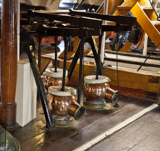
It looks like some copper vessels that allowed for a larger volume of liquid to be discharged as opposed to just the diameter of the main pump body.
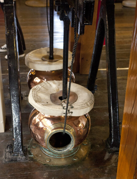
Another view. This appears to be a different set of pumps consisting of two pumps.
- GGibson, GrandpaPhil, mtbediz and 2 others
-
5
-
-
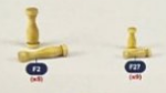
Another quick little job.
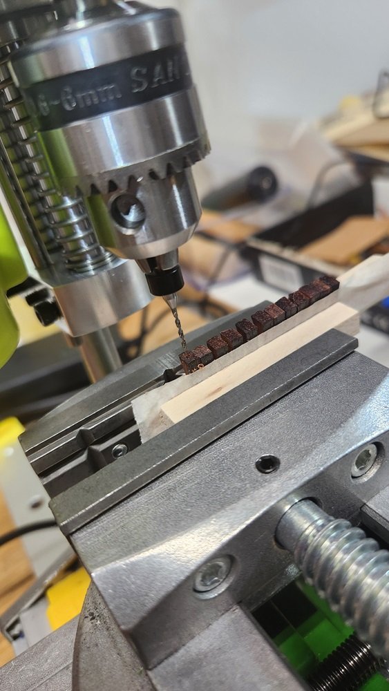
I didn't set this up as tight as I could have. I wasn't concerned with small deviations, but maybe should have been.
These pieces are the tentative quoins for my tentative Rattlesnake cannon. I needed a hole to insert the quoin handle.
With hind sight, a little jig to do them securely one at a time, would give me more precision.. Next time.
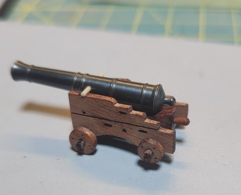
Still in prototyping phase. Experimenting with mahogany for some contrast on the gun deck, as I have chose not to paint.
I will probably go back and do a better job of centering the quoin handles, because it's one of those things I would lose sleep over.
Anyway, just another sea trial for the drill press. It is really up to the task, but I need to prep better.
-
-
I did a little milling operation today.
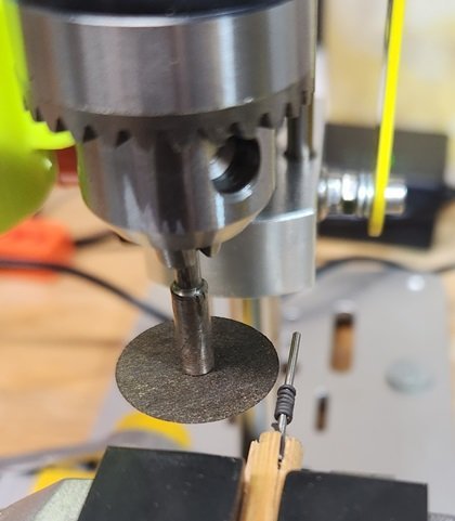
I'm working on some cannon for my Rattlesnake, and they require a lot of split rings and eyebolts.
This method has been gleaned from a lot of discussion about making these things. I would have to say Chuck Passaro is my primary instructor on this.
I have wrapped some 24 gauge annealed steel wire around a #56 drill bit fixed in a dowel.
All the X, Y and Z adjustments took a little doing and there were a few oopsies before I got it where I wanted it.
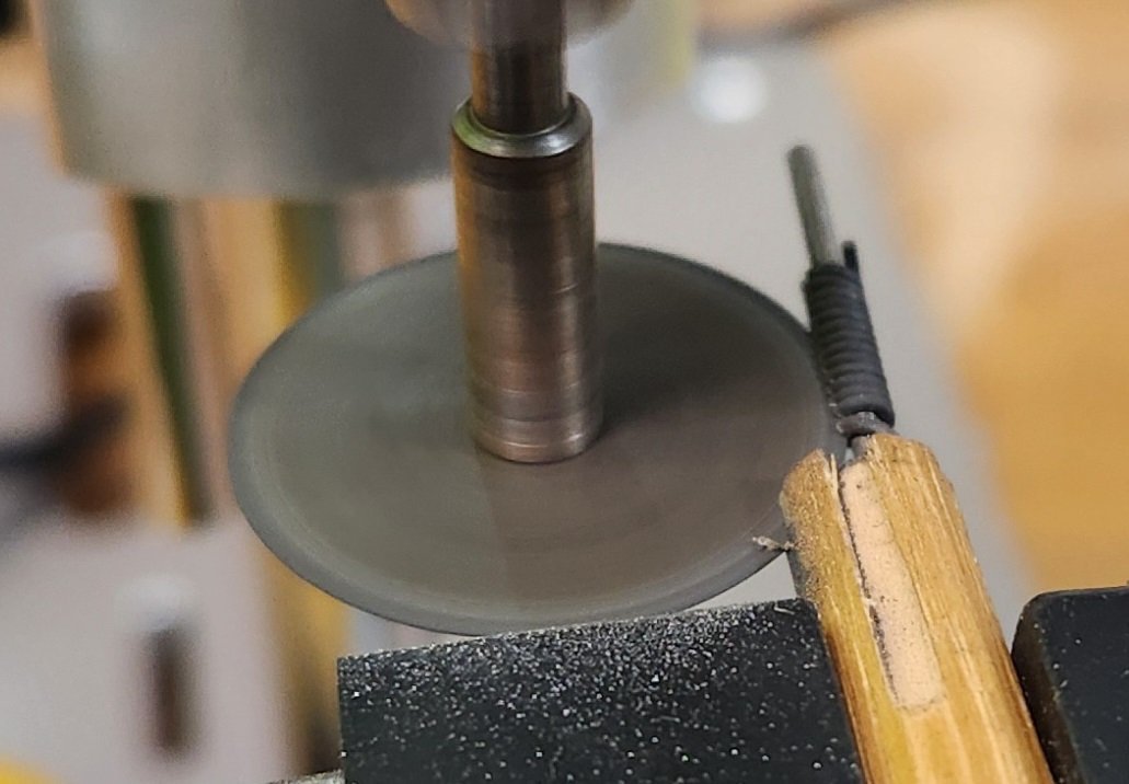
The tool is a .009 separation disk. Chuck P. says he has a saw he uses, but I have decided to go with this. Anyone who uses these discs can attest to how fragile they are. It's not unusual for me to break one just setting it up in the mandrel. If this set-up were not tight, the disc would not make it through the job. I can actually hear/feel a little click when one of the rings is cut through.
This picture is toward the end of the operation.
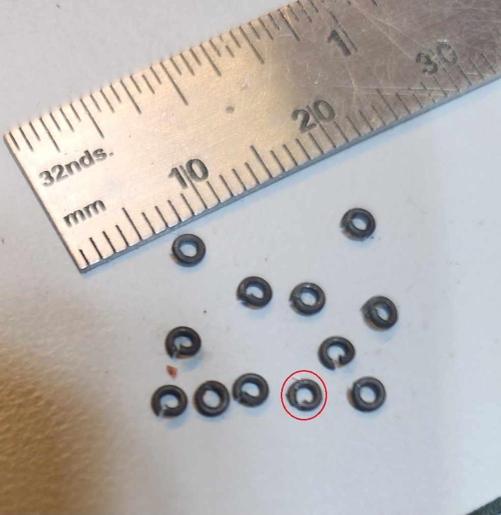
Here is the result. The one with a circle around it snuck in from an earlier effort with a different method.
The open rings close up almost flush with very little pressure.
- oakheart, Thukydides, tkay11 and 5 others
-
8
-
Since you are exploring ideas..
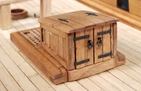
I did a little mix and match on my companion for Resolution. I make my hinges out of black paper.
- iMustBeCrazy, mtaylor and oakheart
-
3
-
Thanks for the info.
I guess I've never done the type of work that calls for that type of precision.
I 'll just have to see if this set up does what I need to do.
- Chuck Seiler, mtaylor and Canute
-
3


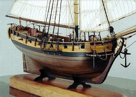
Rattlesnake 1782 by Gregory - Scale 1:48 - Plans from ModelShipways & NMM
in - Build logs for subjects built 1751 - 1800
Posted
Thanks scrubbyj. Really means a lot coming from you, considering the work you do with the laser.