Thukydides
-
Posts
1,270 -
Joined
-
Last visited
Content Type
Profiles
Forums
Gallery
Events
Everything posted by Thukydides
-
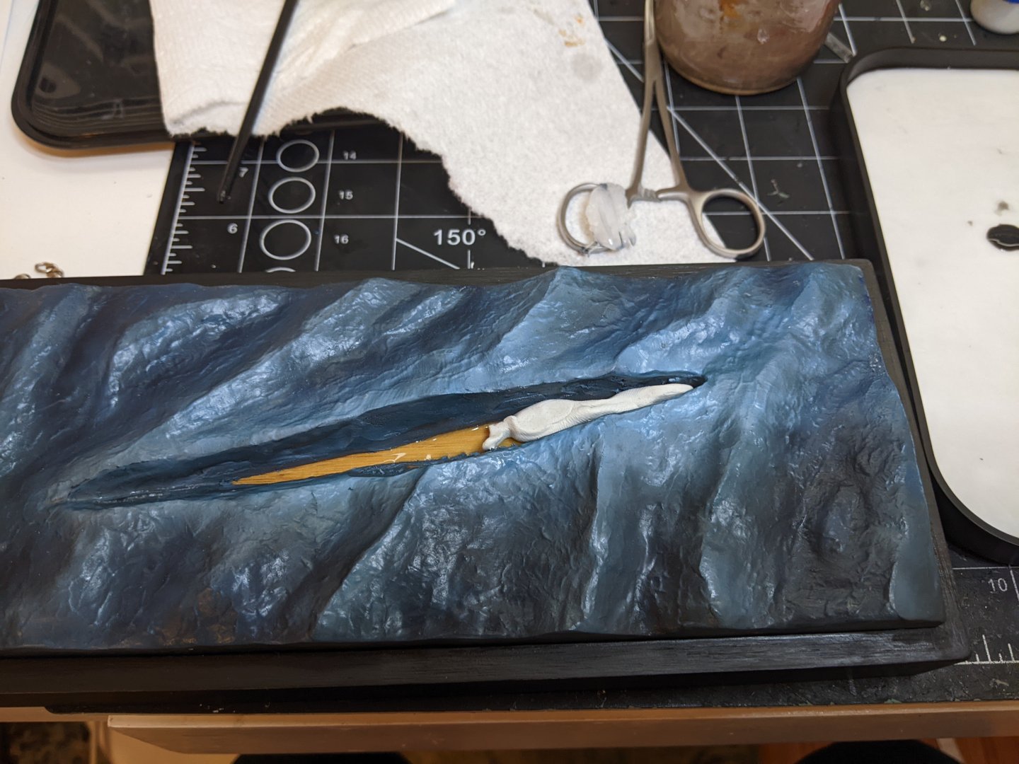
 Painting is now pretty much complete with only a few minor touchup still necessary. However, these will be made after I have secured the model to the base so that was the next step. After test fitting things I added some epoxy putty to the stern area as I needed to make sure it stayed at the correct angle. This will also help to hold the model in place. Then I placed the model in the base positioning it so that the the stern is pretty much level with the water. I want the waves to just be washing over the very end, but not to obscure too much of the model. Then with a toothpick I carefully applied gesso around the edges to fill in the gaps. This doubles as both the means of securing the model, but also is what I will be using for the foam. At this point I was just trying to carefully fill in the gap between the water and the model. Once everything is dried then I will move on to deciding where the foam will extend to.
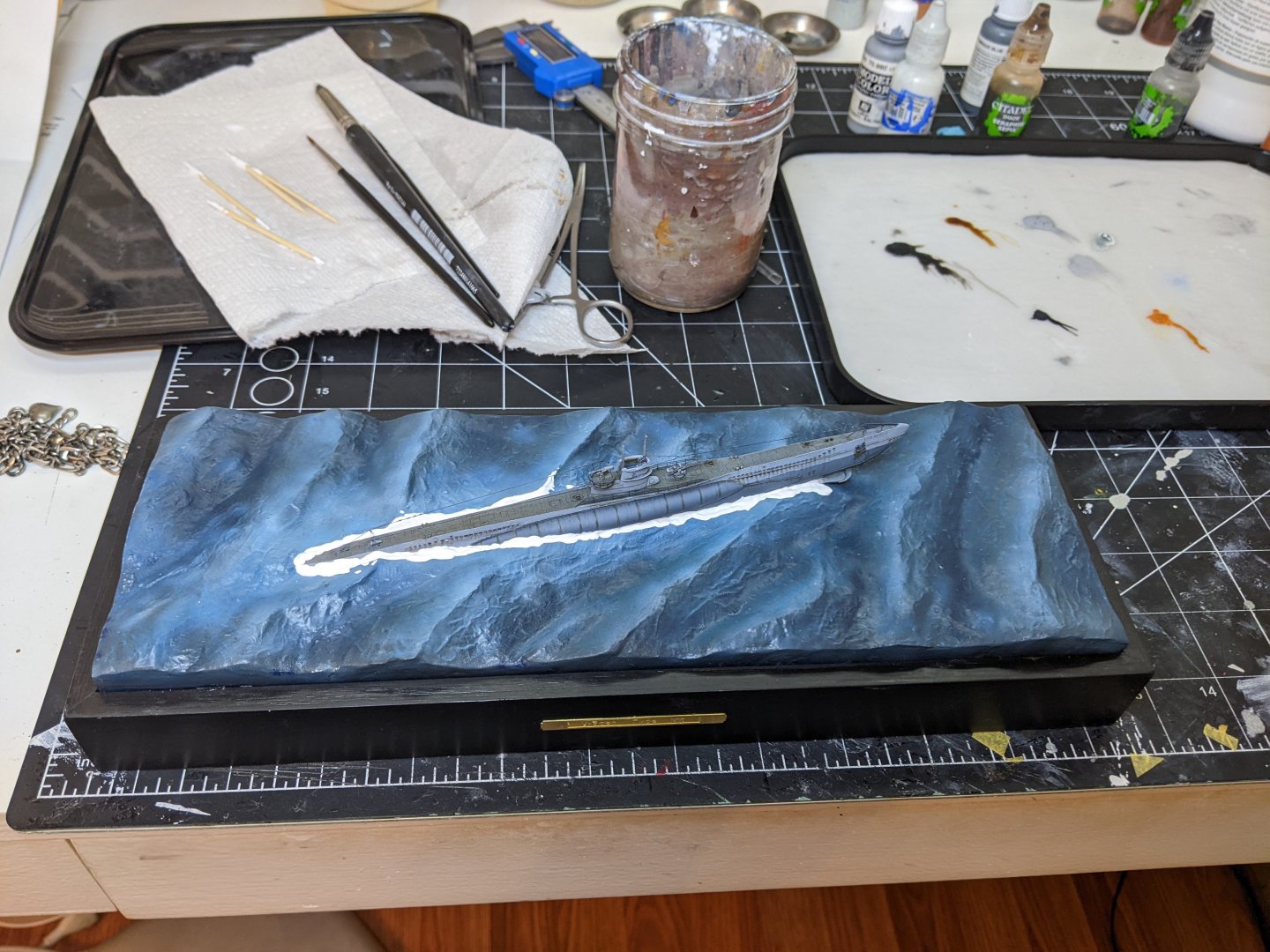

-
I love the miniature lobster trap. On the lobster itself have you ever tried drybrushing. That is a really easy way to pick out detail and generate contrast. Then you could coat it with a few washes of various shades of black and brown to darken the recesses.
- 65 replies
-
- 3
-

-

-
- Maine Peapod
- Midwest Products
- (and 1 more)
-
The top of the sub deck should show you the faring line for that part of the hull, but the angle that the fairing occurs at will change depending where on the bulkhead you are sanding. The best way to do it is to have a test batten ready to hold against the bulkheads at various angles. When it is bent over the bulkheads there should be no space between the batten and the bulkheads. If there is then the hull is not faired enough. In general the process for me is take a sanding stick and fair over multiple bulkheads at once. That helps to get the correct curve. The amount of char visible can also serve as an indicator. However the best check is the batten test.
-
Great job, I like the black background. It makes the excellent planking job really stand out.
- 82 replies
-
- 2
-
-
-
- half hull planking project
- half hull
- (and 2 more)
-
Out of curiosity, I can see from your picture the hooks seem to be cast. Do you cast them yourself?
-
Great job, the boat looks lovely.
-
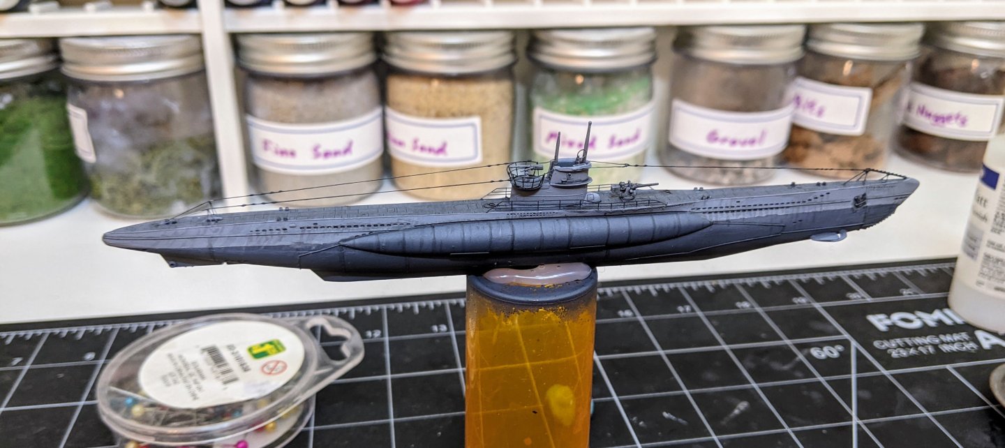
Minor update. I got some more time to paint this evening and made a lot of progress on the weathering. Still some minor adjustments to go, but she is starting to look more like what I was aiming for.
-
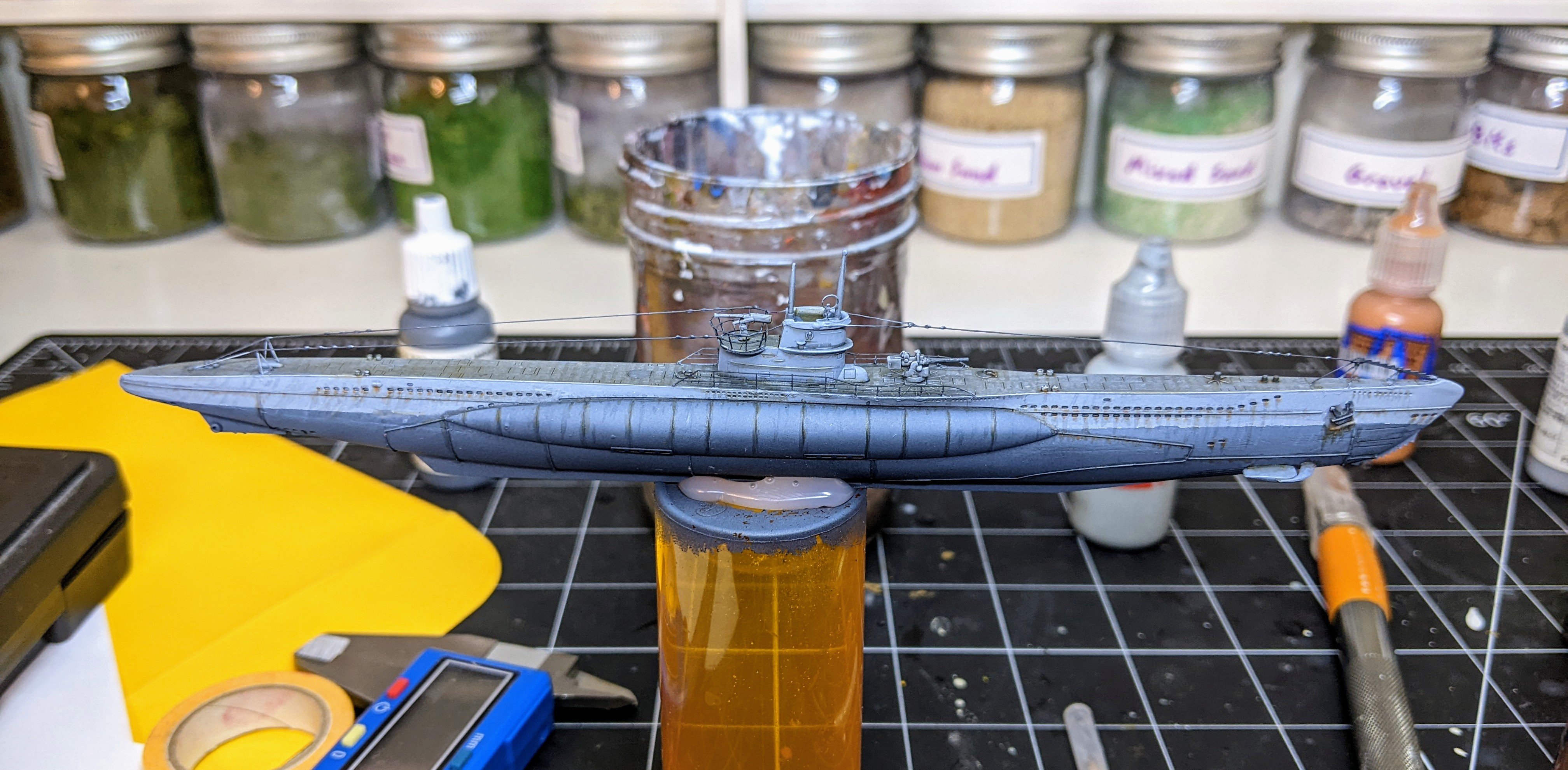
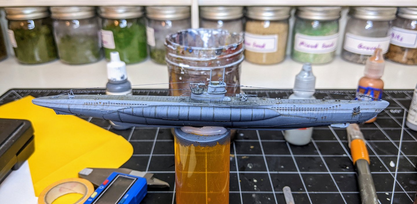
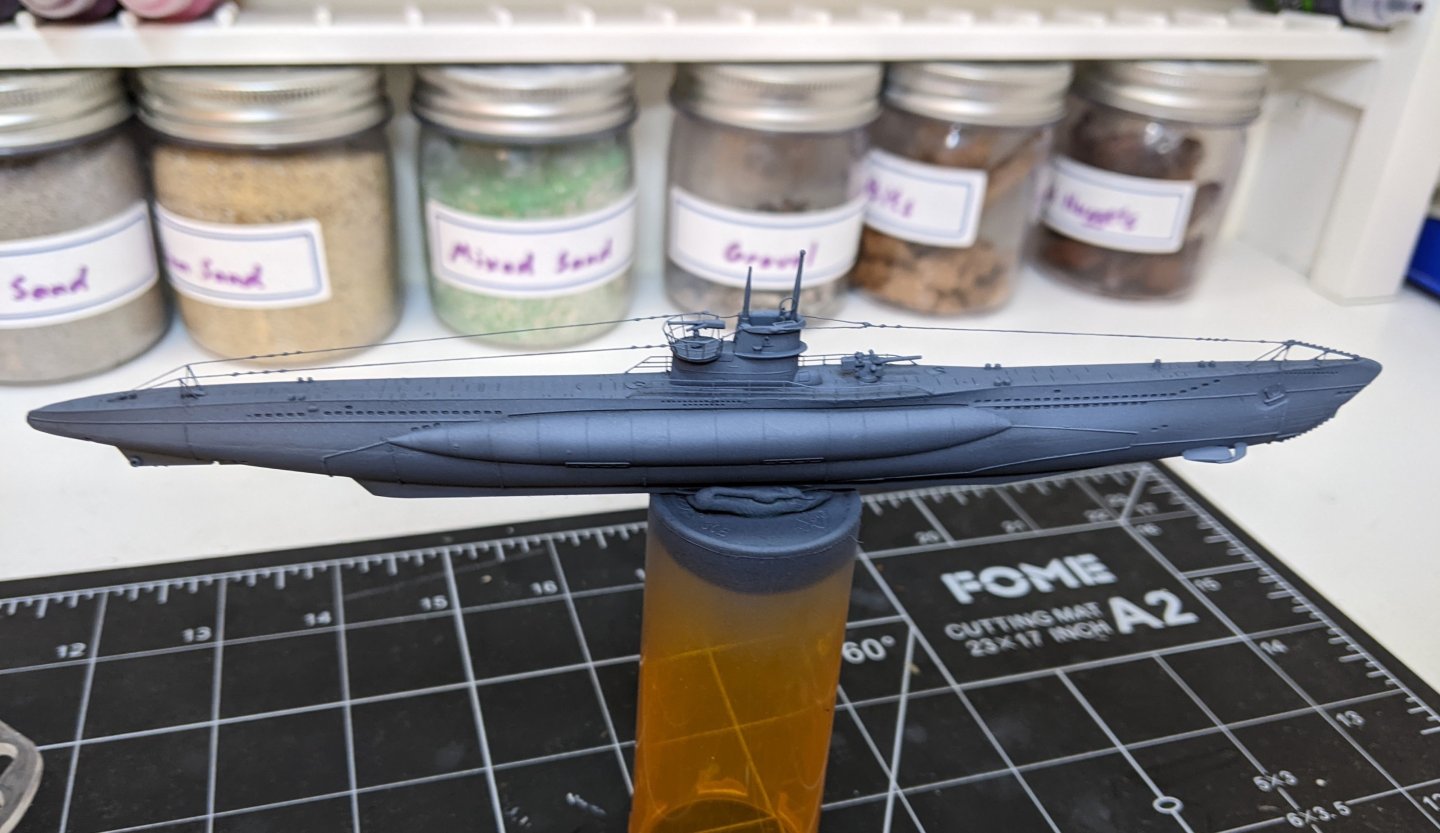
Painting and weathering of the submarine has now begun. The first step was to spray on the colour of the lower hull and also block in some highlights. I used VMC french mirage blue for this. Then I masked off the lower part of the hull and sprayed in a lighter grey (VMC light grey). I was reminded of how much I hate masking off and spraying so I decided to keep it to the bare minimum and rely on brush work for most of the painting. The above picture was taken after I had already applied some black wash to the deck and used a darker colour on a few details., but this is essentially what she looked like after spraying the light grey. Next up is the fun part, weathering and highlighting. My personal workflow tends to see me going back and forth over areas, adding in shadows and weathering and then going back with highlights to correct the lack of contrast and mistakes. I am currently only going back and forth with light grey and black wash trying to get the balance of light and dark streaks right while also lining the panels and picking out the edge highlights. You can see the current state of affairs below. I am not as please with the stern as I am with the bow, but on the bright side most of that will be under water. Also some of the wash has gotten in places it shouldn’t so there is some work remaining to clean up those areas. Once all the highlighting and shading is done I will need to repeat it on the other side and then move on to rust.
-
Not sure what specifically you are referring to, but the gripe does look a bit odd. It is a strange shape, there is no scarph joining it to the knee of the head and the joint is in the same location as the stem joint when they really should be shifted. Also I would imagine that in reality the knee of the head would have been made of at least a few different pieces. That being said most contemporary models just used one piece as they didn’t bother to show this detail. In many cases the joints would be covered up by the cheeks. Thanks, that is totally the reason. One of the issues was most shipwrights were illiterate and even if they could write, describing this would be revealing trade secrets and might put you out of a job.
-
Welcome Nick You should still do one. It is the best way to get help as you go along. I also personally found the practice of documenting my build kept me motivated when I got bogged down in the middle. The help and feedback I got on my log made my first model way better than it ever could have been had I just done it on my own. As others have said you have picked a lot of ship for your first build and I would still advise you to pick something smaller to try first (Vanguard has some really nice cutters). But at the end of the day you need to be interested in your subject or you will never finish it. Good luck.
-
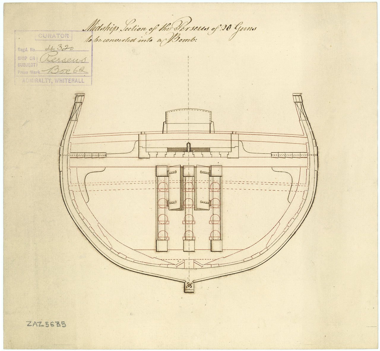
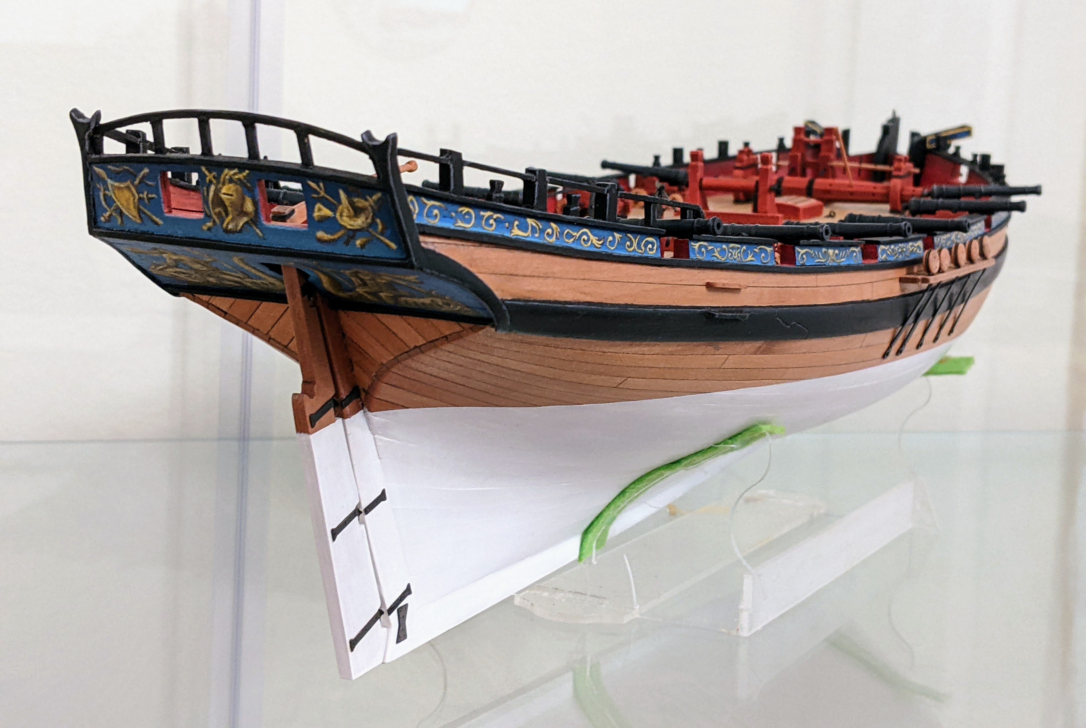
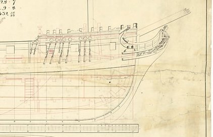
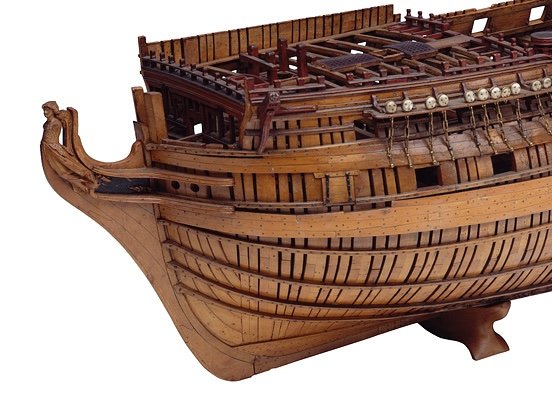
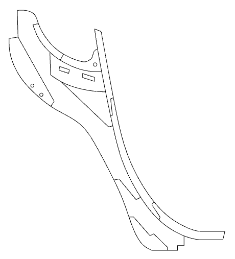
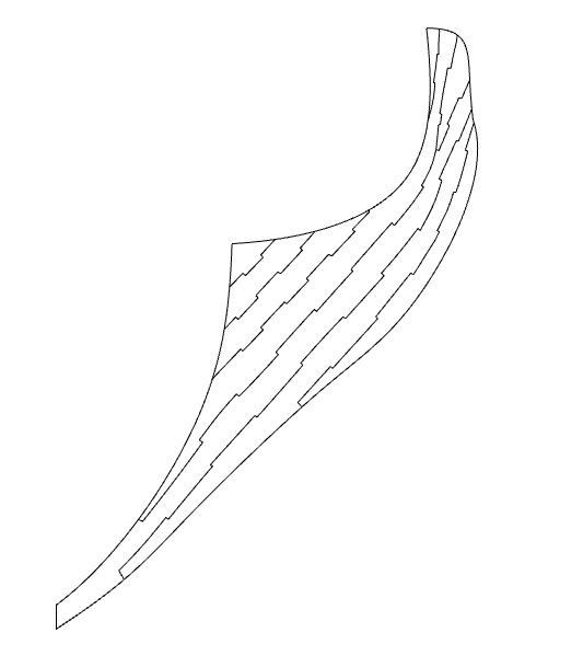
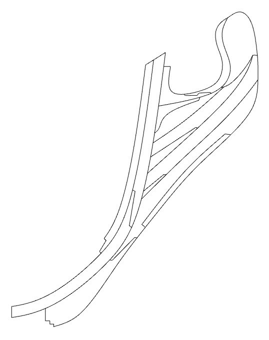
Log #9: Researching the Knee of the Head Part I My design work is getting to the point where I need to start making some decisions regarding how I am going to model the ship. One of the more consequential of these things that need to be decided on is the knee of the head. I am still doing a bunch of reading, but I thought I would share some of what I have found in case anyone has any ideas of other places to look. My goal with this model has been to trace everything back to primary sources wherever possible. I found myself dissatisfied by the information I found in the many modern sources, mostly because they so rarely pointed to any primary documents. This is not to say these works are wrong and I don’t want anyone to take this a a criticism of them. Shipbuilding practices varied considerably from yard to yard. Blaise Ollivier, in his 1737 remarks on english shipbuilding practices (otherwise known as his spying expedition) notes that Depford, Woolwich and Chatham all used different building methods. This means that historical examples of the knee of the head should be viewed not as proscriptive, but as examples. One could probably make a case for just about any reasonable arrangement. That being said, my desire is to stay as close to documented historical practice as I can so that will guide my design decisions. Information on Perseus’ Construction There is limited detail in the contract regarding the construction of the knee of the head for Perseus. The stem is clearly laid out on the draft and the contract specifies that it should be in two pieces with a 3 ½ foot scarf. However, apart from the overall shape of the knee of the head laid out in the draft, the only details given are directions for the gripe to be covered in lead on the leading edge up to the waterline and for the end of the head to extend 8 ft 5 in from the stem. Draught of Camilla, National Maritime Museum Four draughts for Perseus’ sister ships, Sphinx, Camilla, Daphne and Vestal showing the carvings and decorations also show the location of the gammoning hole. It is reasonable to assume that the location would be similar on Perseus. However there is no info provided for any of the Sphinx class regarding the specific makeup of the knee of the head. Knee of the Head Examples 1737-1760 Contemporary depictions of the knee of the head are few and far between. Much of this relates to the lack of publications from the period on shipbuilding practices. Modern secondary sources when depicting the knee of the head tend to show similar patterns typified by the below example from Goodwin. However, contemporary records are far more varied and it is unclear what the original source for this arrangement is. The Knee of the Head, 18th Century, Goodwin, The Construction and Fitting, Redrawn Ollivier’s 1737 observations on English shipbuilding practices includes one diagram of the knee of the head as part of his observations of the Deptford dockyard. He describes how English shipwrights made a mould of the various parts (lacing, face piece, etc…) and then filled these moulds with what timbers all with a common curve. These timbers were fastened together with hooked scarphs. Ollivier was clearly impressed by this method of construction which he said was “more simple, no less solid, and beyond compare less costly than that which we employ.” Ollivier also notes the use of an iron dovetail plate used to fasten the gripe to the stem. This contrasts with later examples which show a horseshoe plate. Knee of the Head for a Ship of 80 Guns, 1737 Ollivier, 18th Century Shipbuilding, redrawn The next example shows up sometime after 1745 in a sectional drawing held by Sjöhistoriska Museet. The drawing is reproduced by Lavery in his book Ship of the Line and shows a 60 gun ship built according to the 1745 establishment. The knee of the head is made up of a large number of roughly parallel strakes though, unlike the Olliver example, they are not scarfed into one another. The drawing features a much longer cutwater than generally is depicted on modern reproductions, and like the Ollivier example, the lacing buts against the stem instead of running down to the gripe. Curiously, it appears that it has two false keels, though as the picture is at low resolution it is hard to tell for sure. Knee of the Head for a Ship of 60 Guns, 1745 Establishment, Sjöhistoriska Museet, redrawn This practice appears to have continued on into 1760 as can be seen on a model of Bellona (74). The Bellona model is unique in that it is the only contemporary model I have been able to identify which shows the components of the knee of the head. Though the pieces that make up the knee of the head are larger than both Ollivier’s diagram and the example reproduced in Lavery, they do follow the principle of the common curve. There are no scarfs locking the pieces together and this could indicate either they were not used by this particular shipwright or possibly that the model maker simply neglected to include those details. One particular detail on the model which stands out is the long cutwater which extends from the main piece all the way to the gripe. This is even longer than the cutwater on the Lavery example and contrasts with the relatively short cutwater that can be seen on many modern examples. There is no plate fastening the gripe to the stem shown on the model. Model of HMS Bellona, Circa 1760, National Maritime Museum I am still working on documenting and researching early 1800s examples though it is questionable how applicable they are to Perseus given that around 1800 there was a number of changes to how the knee of the head was constructed. They and also a french example from around the time of Perseus’ construction will be discussed in Part II. If anyone knows of any other examples, particularly any dating to the late 1700s I would love to hear about them.
-
As always your research and execution on the rigging is second to none.
-
HMS Sherborne - Caldercraft vs Vanguard
Thukydides replied to nheather's topic in Wood ship model kits
If money is no object then yes I think the Vanguard one is a better choice. That being said if you take your time you should be able to do a fine job of the Caldercraft one. Another option I would throw my two cents in for is Vanguard's Alert. A slightly bigger cutter I feel it has more scope for kitbashing if that is your thing. -
Yes I know the feeling. Trying to puzzle out technical french with a combination of google translate and my limited high school French is a difficult process. Looking forward to seeing what you find.
-
She is looking fantastic Derek. Good to see you back at it.
-
I am always in favour of more painting so give it a try you have nothing to loose painting onto the paper. Just painting over it will give it a more natural look than a printed design will. If it doesn’t turn out well you can always default to just using the printed version.
-
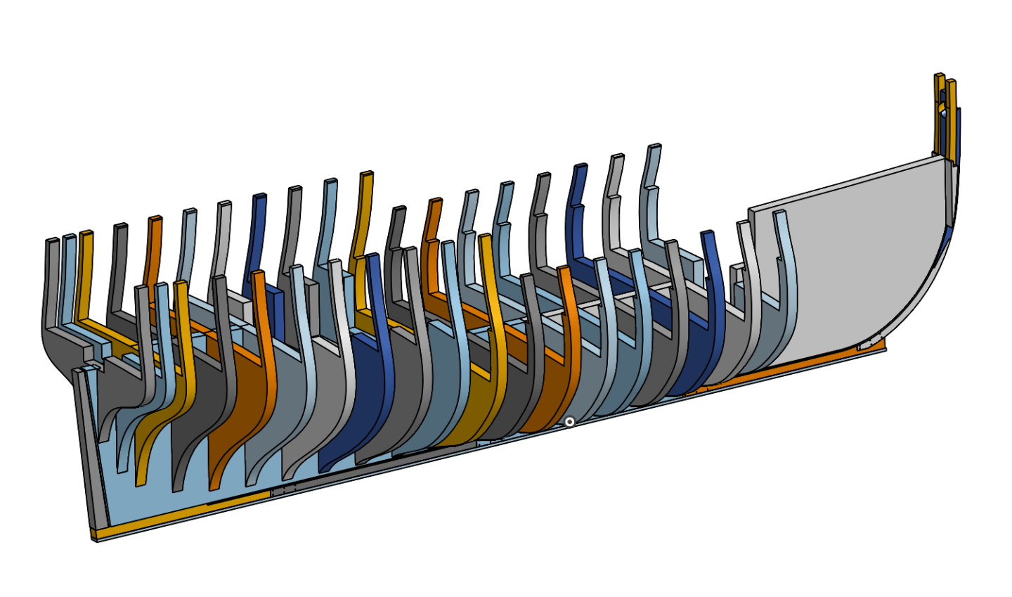
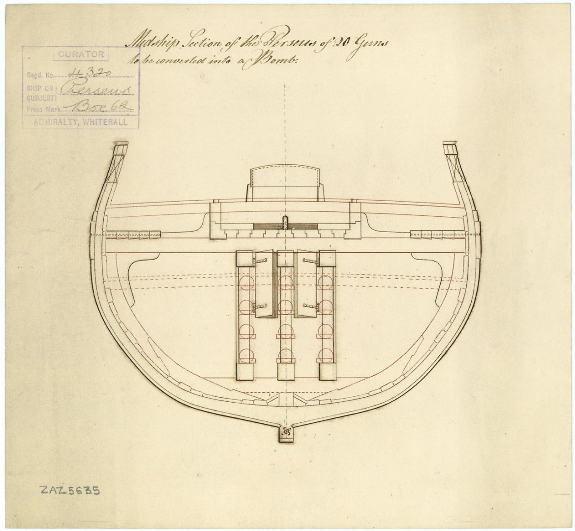
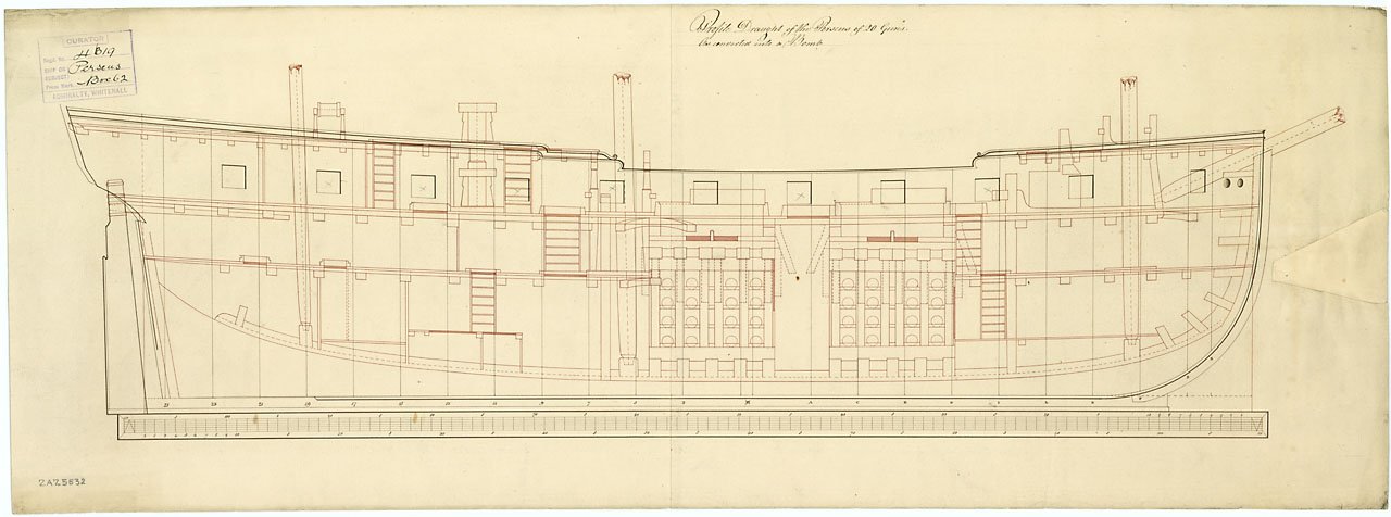
Log #8: Service History Part VI - Conversion to an Unrated Bomb Ship Perseus’ time as a 6th Rate Post ship came to an end when she was converted to an unrated bomb vessel. The plans for her conversion were drawn up sometime in 1797 and in May of 1798 she was commissioned as a 10 gun bomb ship under Commander James Oswald. The plan for her convesion is interesting as it shows a number of changes to her layout including an extra bulkhead under the quarterdeck and changes to the positioning of the ladderways. The former likely occured early on in her career as I have a letter from George Keith Elphinstone to the dockyard requesting the alteration, but in the case of the ladderways it is impossible to know for sure if they represented changes made at the time of conversion or if they simply were documenting changes previously made. The sectional plan confirms many of the timber dimensions in the contract indicating that there were limited changes in this regard to the ship over her lifetime. She served under Oswald until August 1799 when he was succeeded by Lieutenant Henry Compton who was subsequently promoted to commander. Perseus served in the Mediterranean for this period participating in the blockade of Malta. However, by this point Perseus was showing her age and sustained so much damage in a gale that she could not be repaired on station. Compton was ordered by Lord Keith (the same Lord Keith who was her first captain) to return to England with a convoy. The poor state of the Perseus resulted in her being ordered to Woolwich for repairs. In March 1803, Commander John Melhuish took command of Perseus. The most notable action of Melhish’s command was the Bombardment of Dieppe in September 1803. In company with HMS Immortalite(36) and HMS Explosion, another bomb vessel, Perseus bombarded the Dieppe batteries and seventeen vessels, most of which were in the process of being constructed in the port. They then proceeded to St. Valery-en-Caux and bombarded ships under construction there. However, as historian William Clowes notes, “It is doubtful whether very much damage was done.” In May 1804, Commander Thomas Searl was given command of Perseus. There are no significant events recorded for his time in command and Perseus was broken up in September of 1805 bringing to an end an almost 30 year career. On the design side of things I am slowly working on finalizing the bulkhead structure. I realized during my redesign that I actually had room to increase to a larger thickness of plywood for the bulkheads and so have done so to give greater strength to the design. You can see a picture of the current state of affairs below. Thanks to everyone who has stopped by to take a look and for the encouragement.
-
In terms of which has the most info, there is a surprising amount on all of them (except for narcissus). I would recommend taking a look at three decks (https://threedecks.org/index.php?display_type=show_class&id=229) which lists the history of them all. It is a great starting point for research. There are very few paintings of sphinx class ships so not much in the way of visual representation other than the bowl I mentioned above. There is one painting of Camilla, but very late in her career. There is one other painting claimed to be of camilla, but I am pretty sure it is not her. There is one painting by Serres which shows a number of English ships (two of which are Camilla and Galatea), but it is impossible to know which ones are them. In terms of plans full sets of plans are available for them all, but Sphinx, Camilla, Vestal and Daphne all have plans which include their figurehead and decorations so maybe that makes them a better choice.
-
Fantastic work. I look forward to seeing the carrack, I think that should be a very interesting build.
-
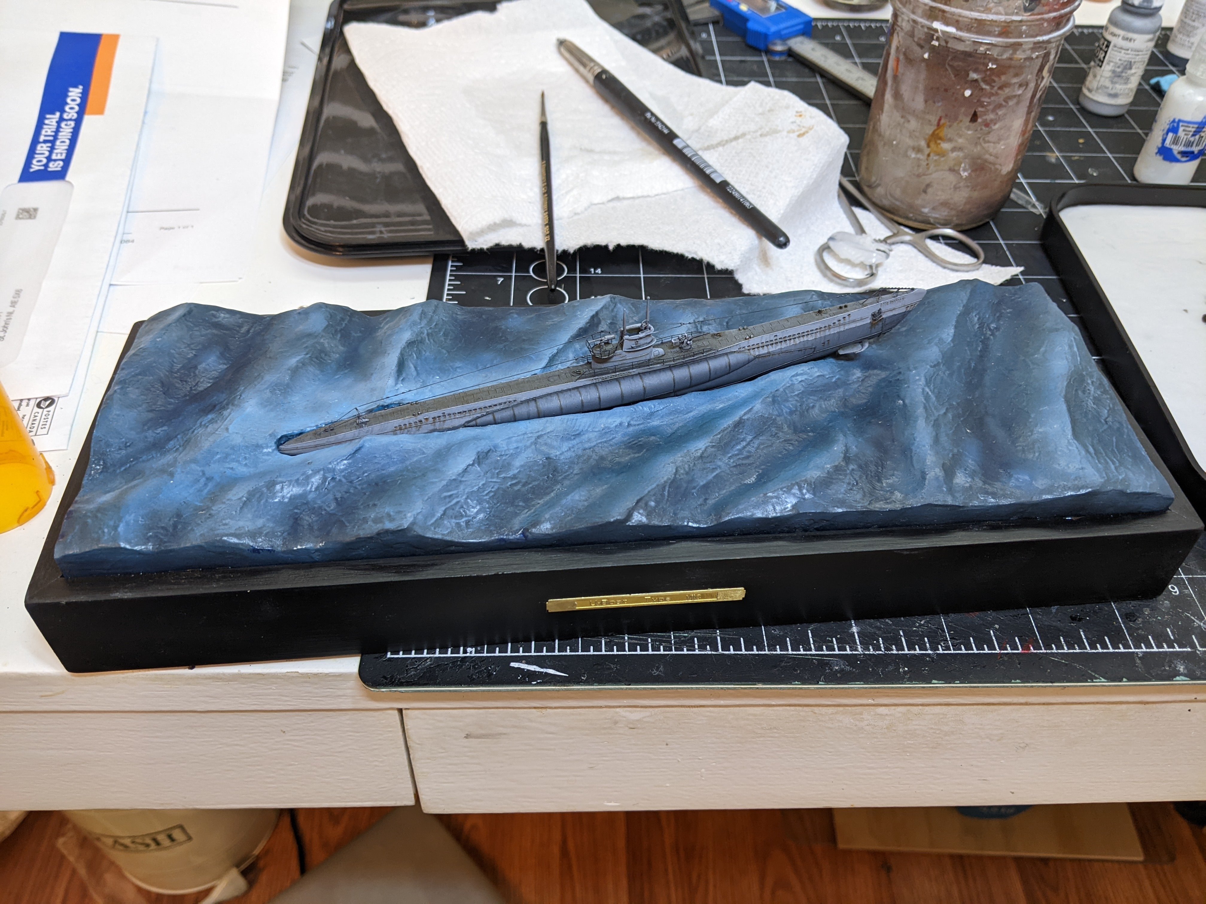
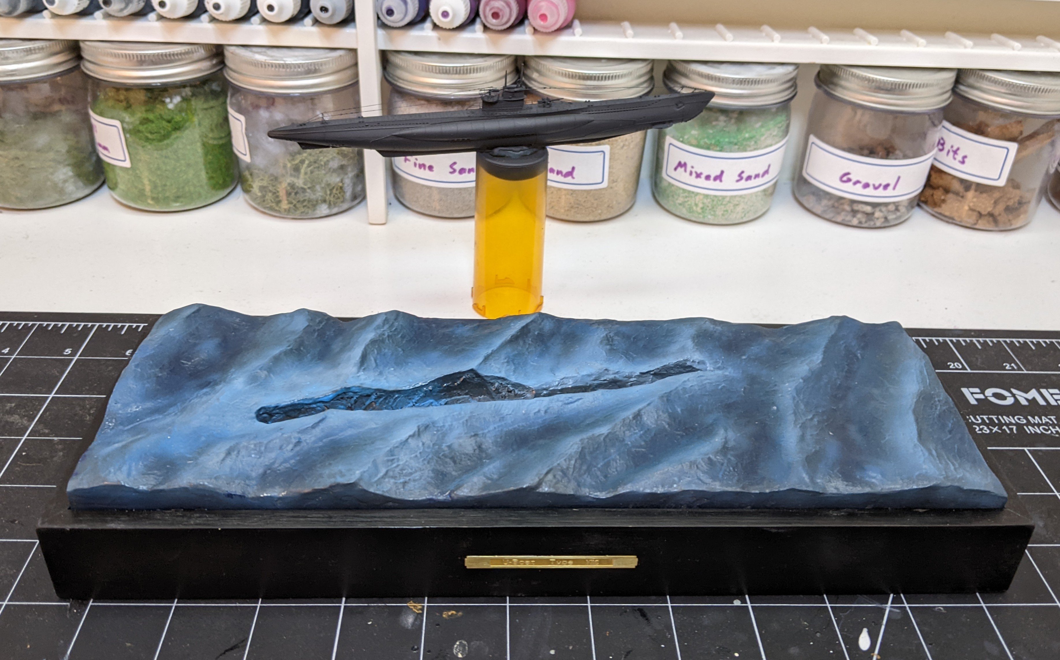
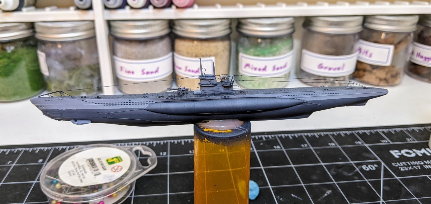
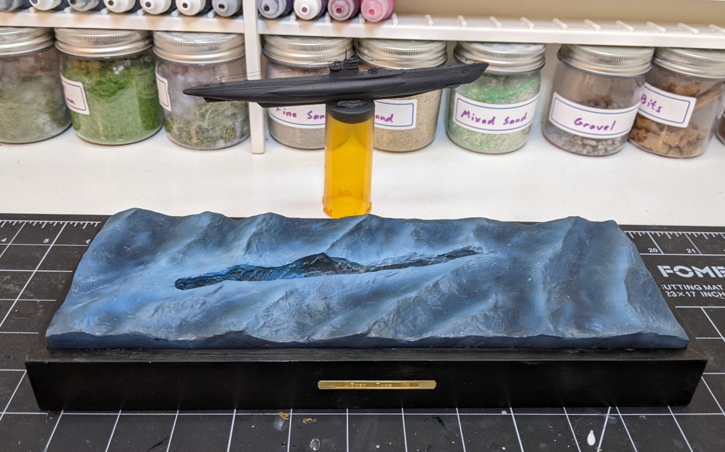
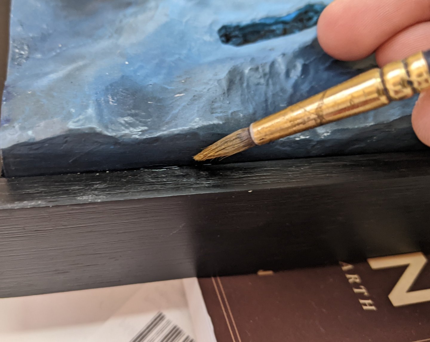
Minor update. I have finished the base of the water. All the foam details still need to be added, but those won't go on till the uboat is ready to go in. I covered the whole thing with two coats of gloss varnish, but it ended up a bit too shiny so I went over it all with a coat of satin. Since I am depicting a relatively stormy sea I don't want a huge amount of reflections. I also glued it onto the base and added the brass label that came with the kit. Next up I need to break out the airbrush again and get back at the uboat itself.
-
Great job Ronald. Those joints look nice and precise.
-
The boats are looking really good. Those ebony Wales do look very nice.
-
If it was me I would do it in the opposite order and not bother with masking tape. Masking tape when hand painting has a tendancy to have paint bleed under it unless it is placed perfectly and on curved surfaces it is pretty much impossible to place it perfectly. I would paint the rail first not worrying about if I go over as the black will cover grey very easily. As a general rule all other considerations aside you paint the colours that cover best last. Also in this case getting a clean line will be much easier with the black. Just drag a round brush at an angle along the flat surface just short of where you want the line to be. Then with you second stroke do it again, but just edge a tiny bit closer. If you are methodical and careful making sure to have your hand resting on something you should get a very clean line. Getting a clean line in the other order will likely be harder as you are having to point your brush in towards the hull to get the sides of the rail. I show the proper positioning for the brush in the picture below (note this is a bad brush, you should use one with a sharper point). Just imagine the black part is the top of your rail and the side I am running the brush against is the hull above it.
-
That is always the problem. By the time I finish the model I sort of know what I am doing. Unfortunately too late to benefit the model...