


Paul Le Wol
-
Posts
486 -
Joined
-
Last visited
Content Type
Profiles
Forums
Gallery
Events
Posts posted by Paul Le Wol
-
-
Hi Gary, thank you for joining the adventure. I’ve been enjoying this scratch building so far. Seems to be a more relaxed pace. Just a pile of wood patiently waiting to become something. ( Hopefully 🤞 )
- thibaultron, FriedClams and robert952
-
 3
3
-
Panteg, your planking is looking great!
-
Hey Denis, thank you. It’s great to have you along!
- robert952 and thibaultron
-
2
-
-
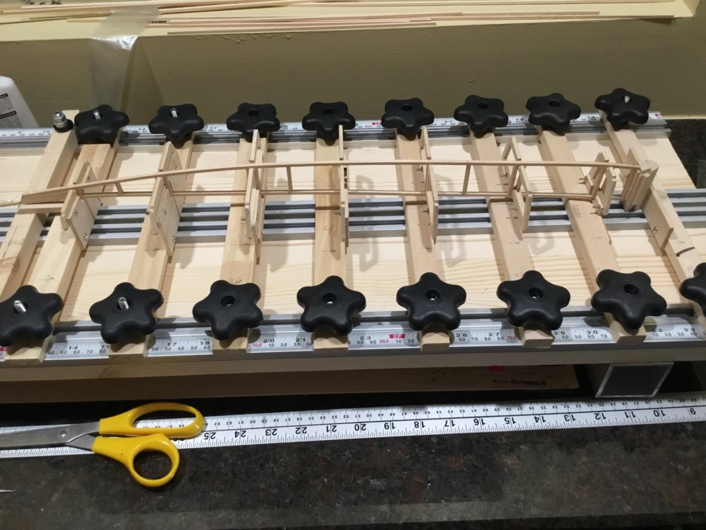
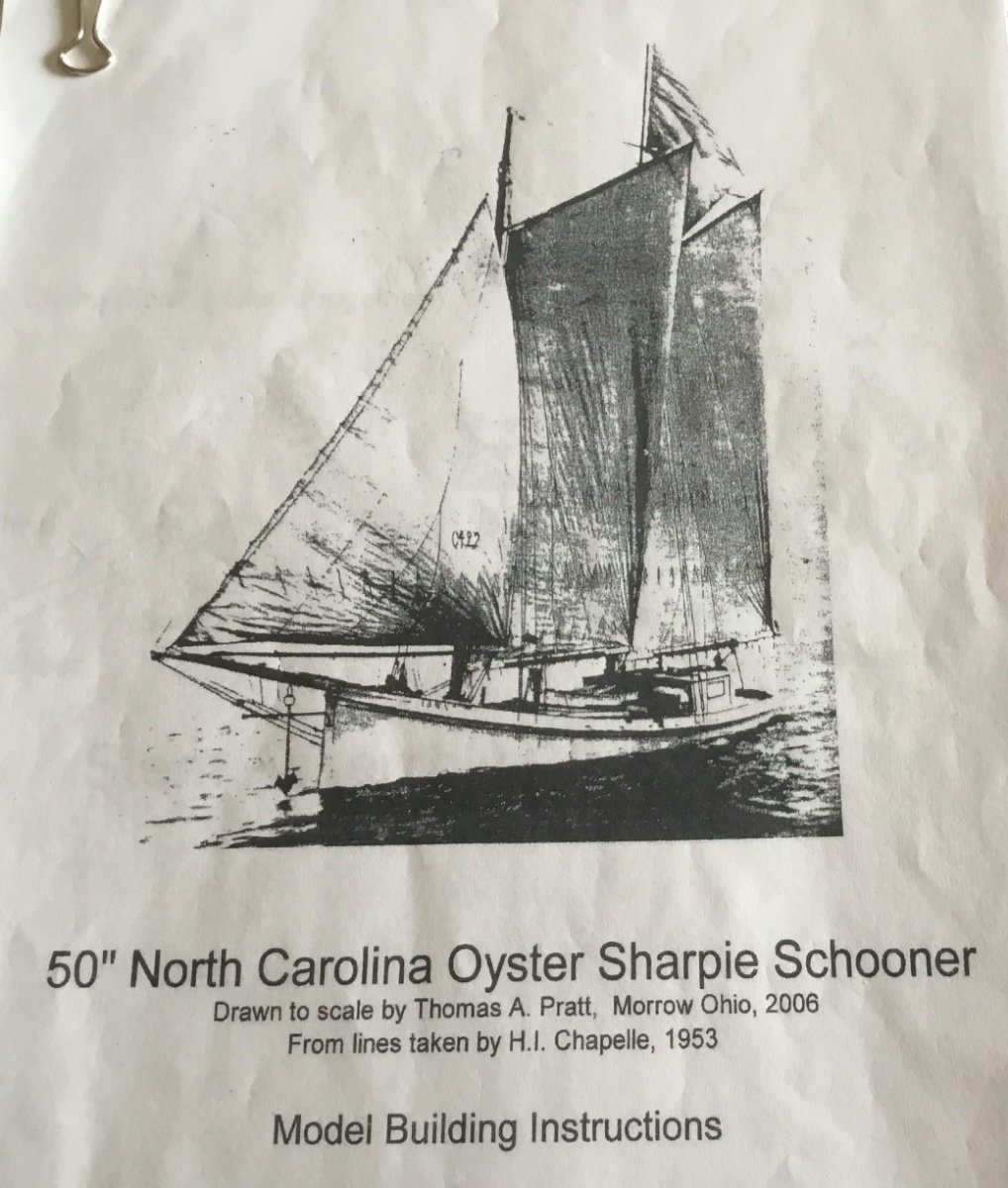
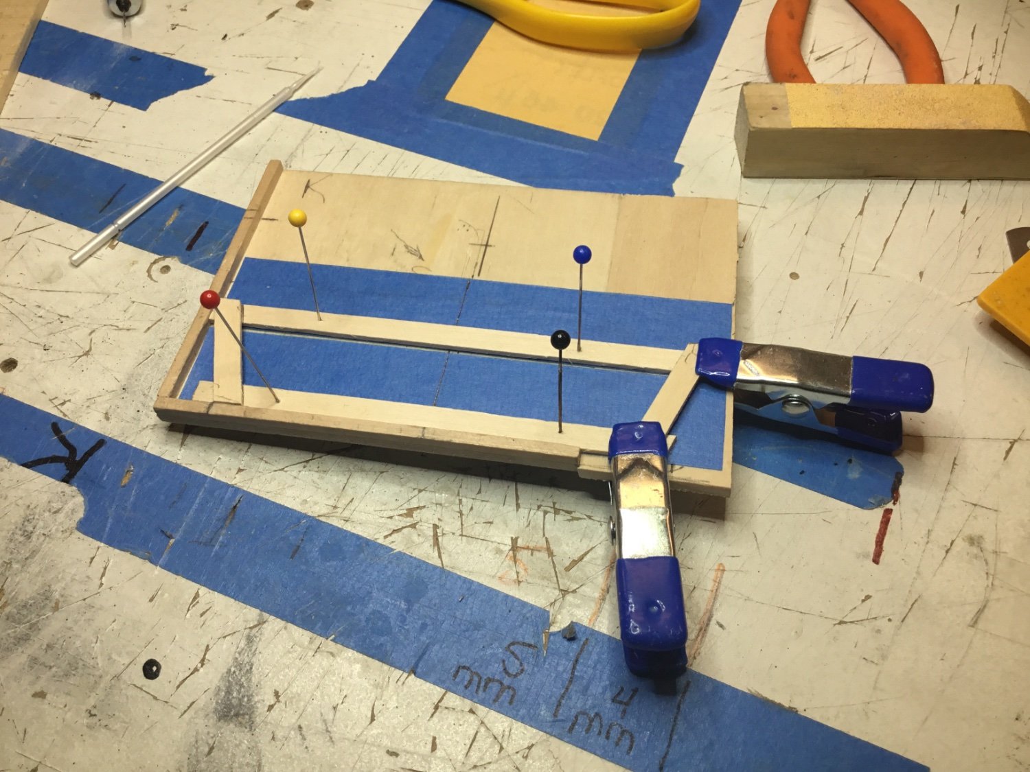
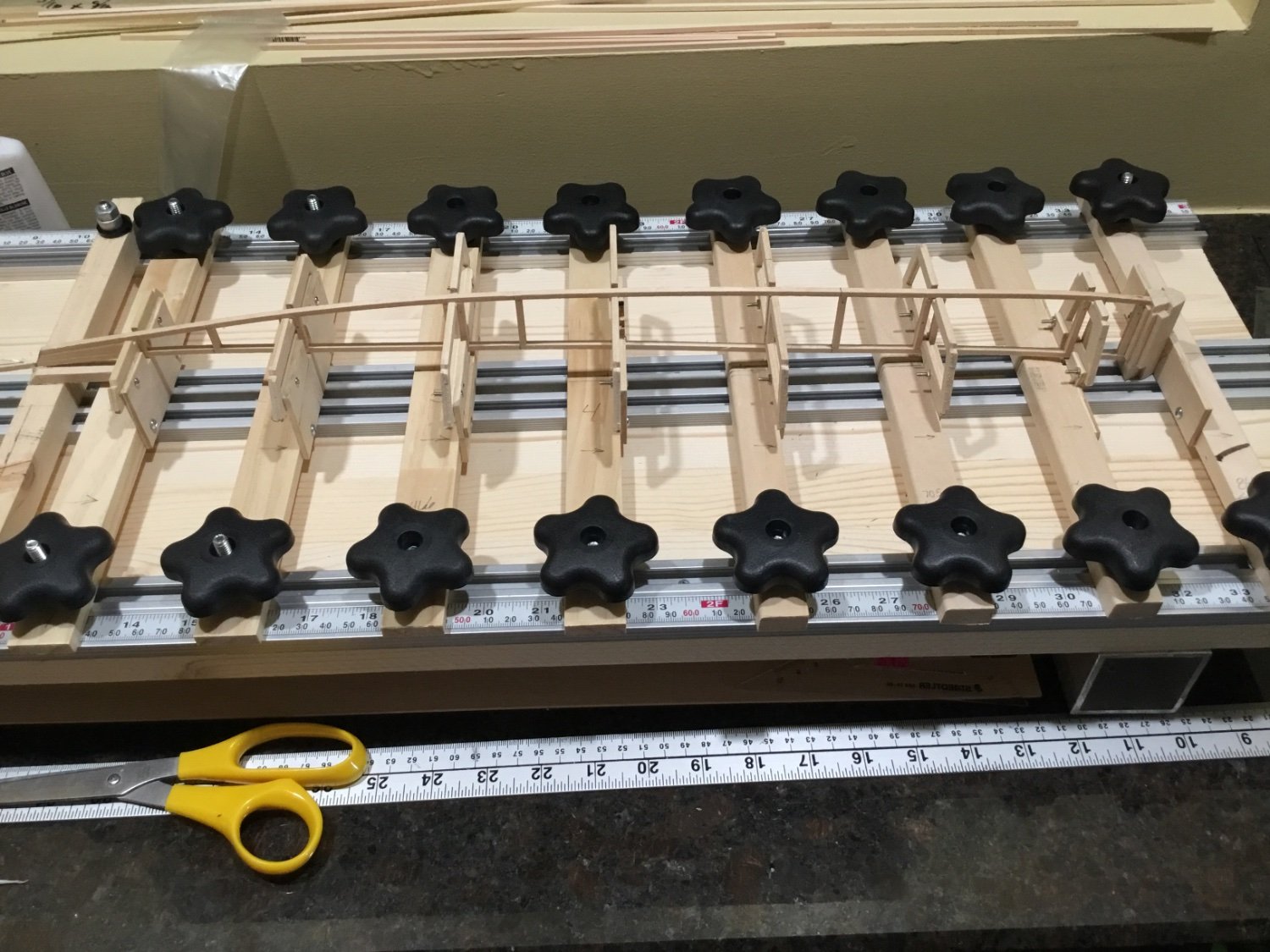
Hi Everyone, this build of a 44’ North Carolina Oyster Sharpie will be my first scratch build. The plans were bought from US Vintage Model Yacht Group. ( USVMYG ) They are drawn by Thomas A Pratt, taken from the lines of Howard Chapelle. They are a digital download with the plans and directions for a 50” model on one pdf and photos and directions of a 50” model being assembled on a second pdf. Acrobat Pro was used to scale the drawings to 1/24 ( 22”) using the tile function to print them out. All of the measurements are taken directly from the printed drawings. Detailed instructions are given on how to make the build board but I’m using the adjustable board that I already have. The inner stem is made first.
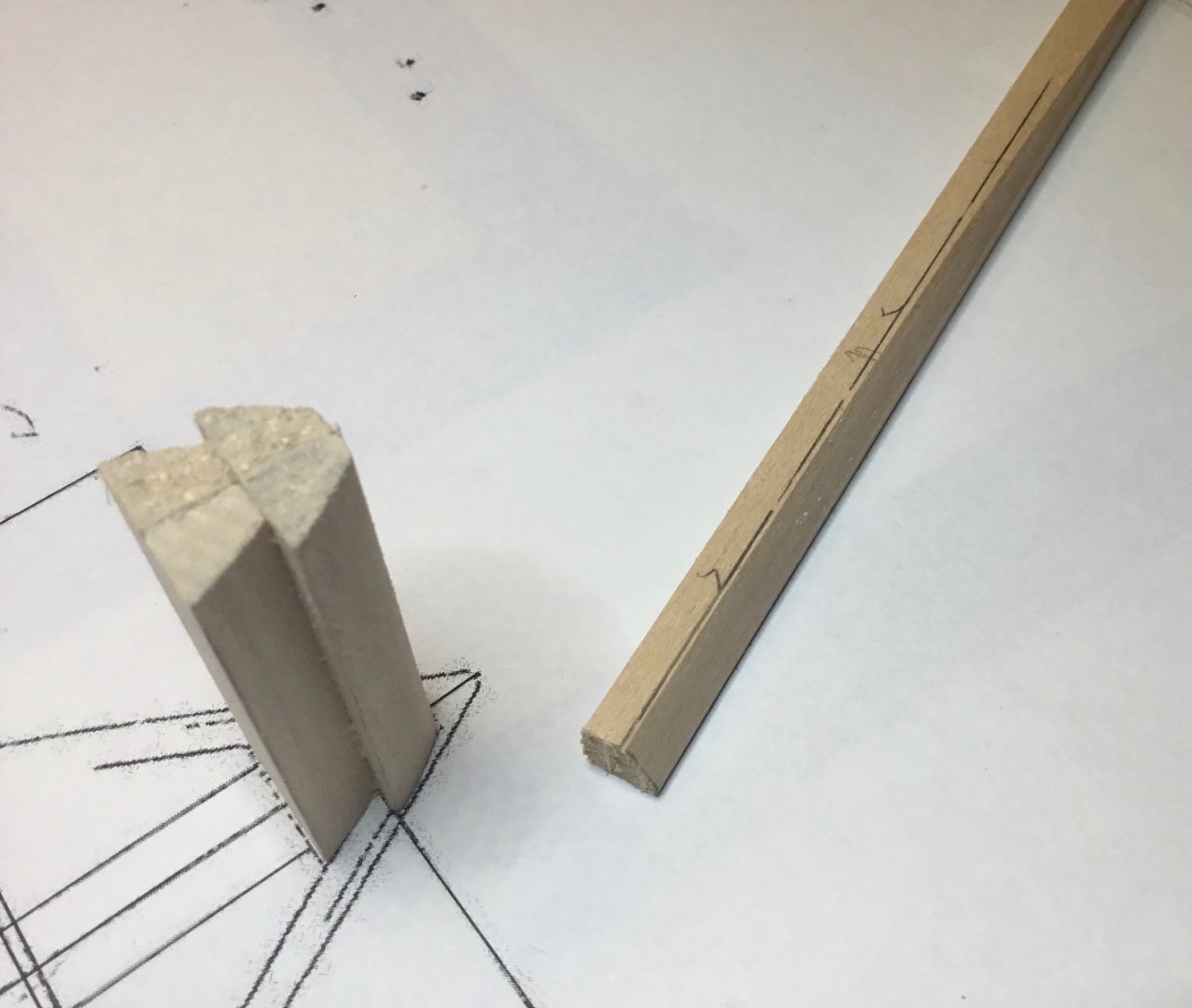
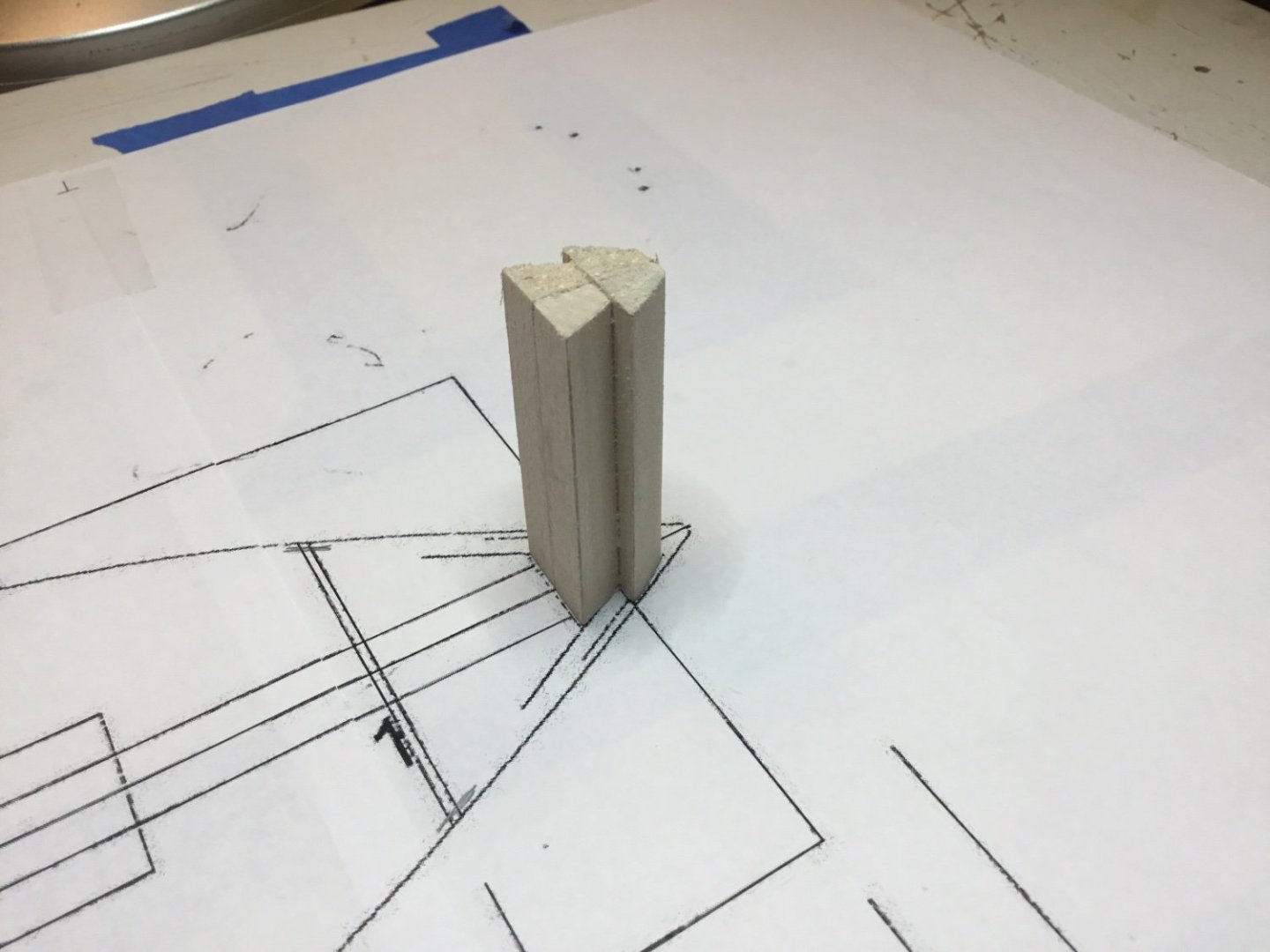


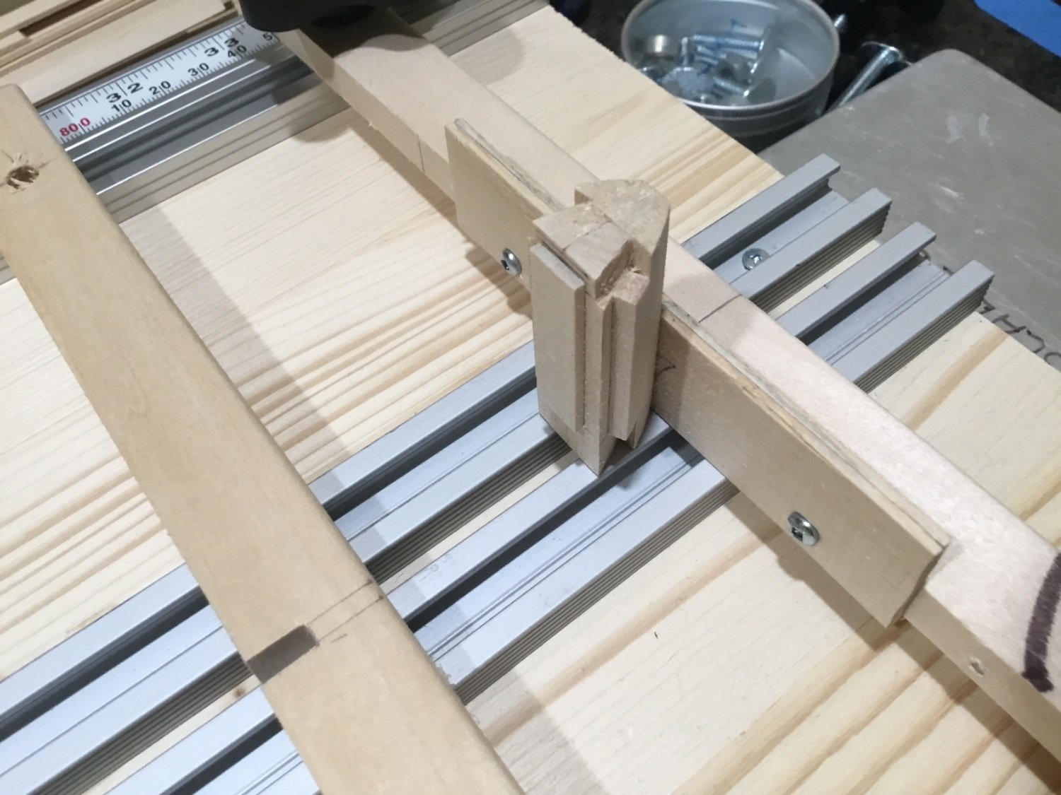
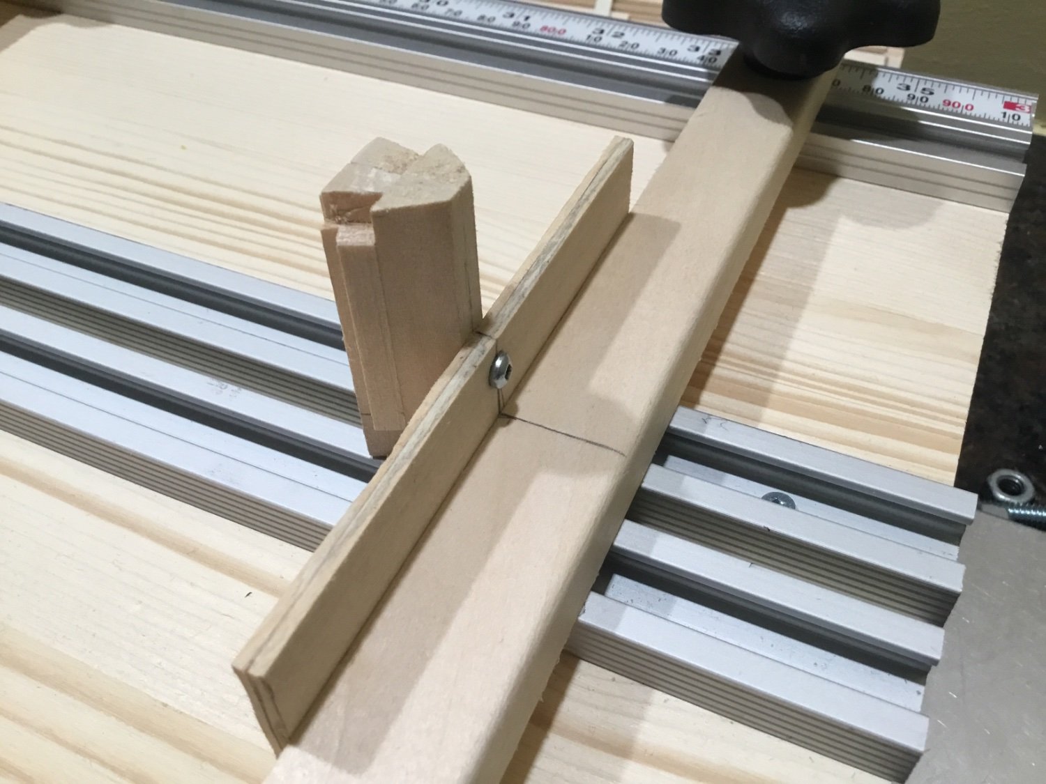
The inner stem is made from 1/4 x 1/4” basswood strip with one side planed at an angle so that the adjacent side is 1/8” wide. When all four pieces are glued together the forward side will be 1/4” wide to accept the 1/4 “ stem. Notches are cut at this time to accept the shear logs and the chine logs.It is mounted to the build board and all measurements are taken from this point.. The hull lines are all straight so I took the measurements from the drawing and started making frames from 1/16” strips of basswood.
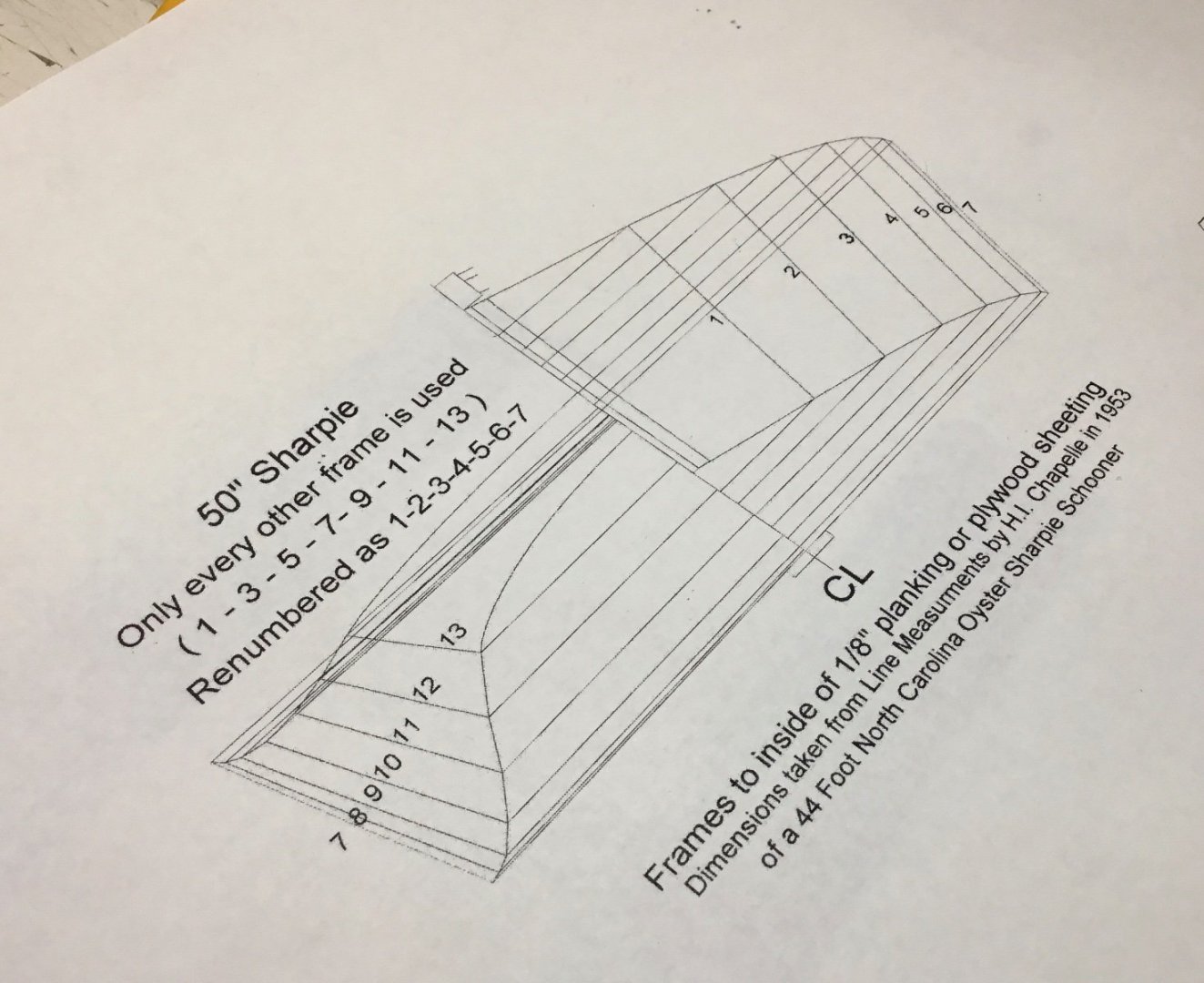

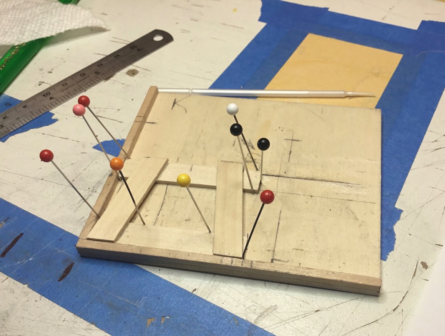
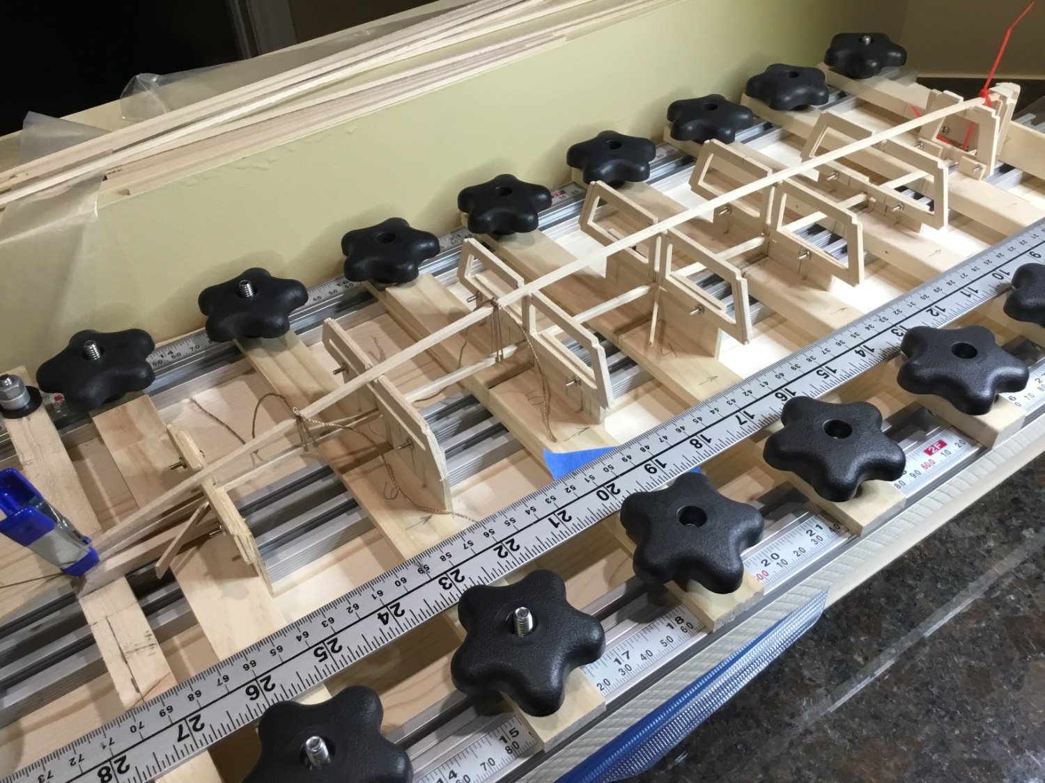
The frames are attached to the build board using 4-40 hardware to eliminate any cutting later on. Notches are cut for the keelson which consists of three 1/8” strips of wood. The king plank sits on top of the frame and will eventually be adjusted for the curvature of the deck. Three 1/8” strips were used in case the center piece needs to be removed for the center board. ( But that probably won’t happen)


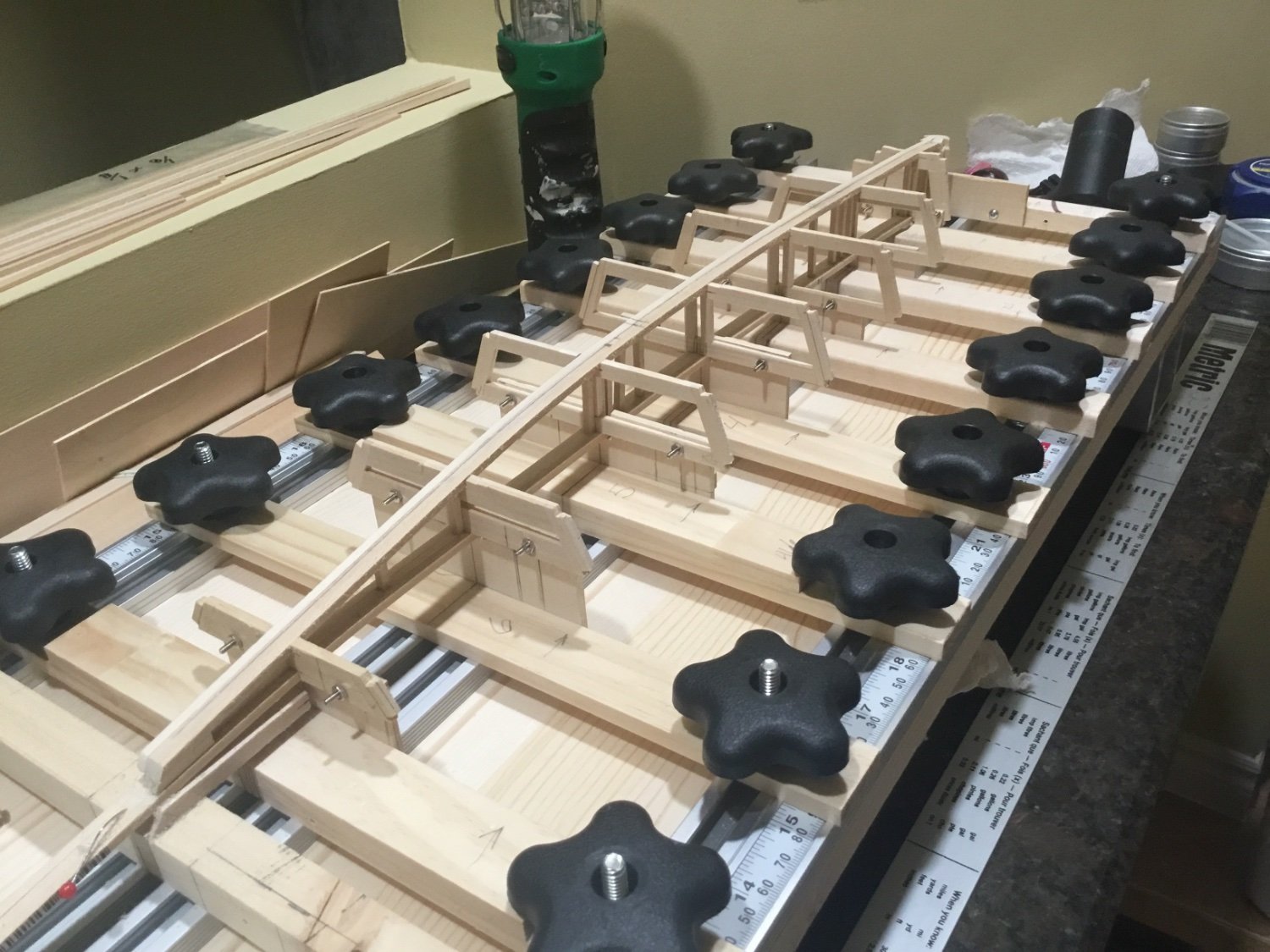
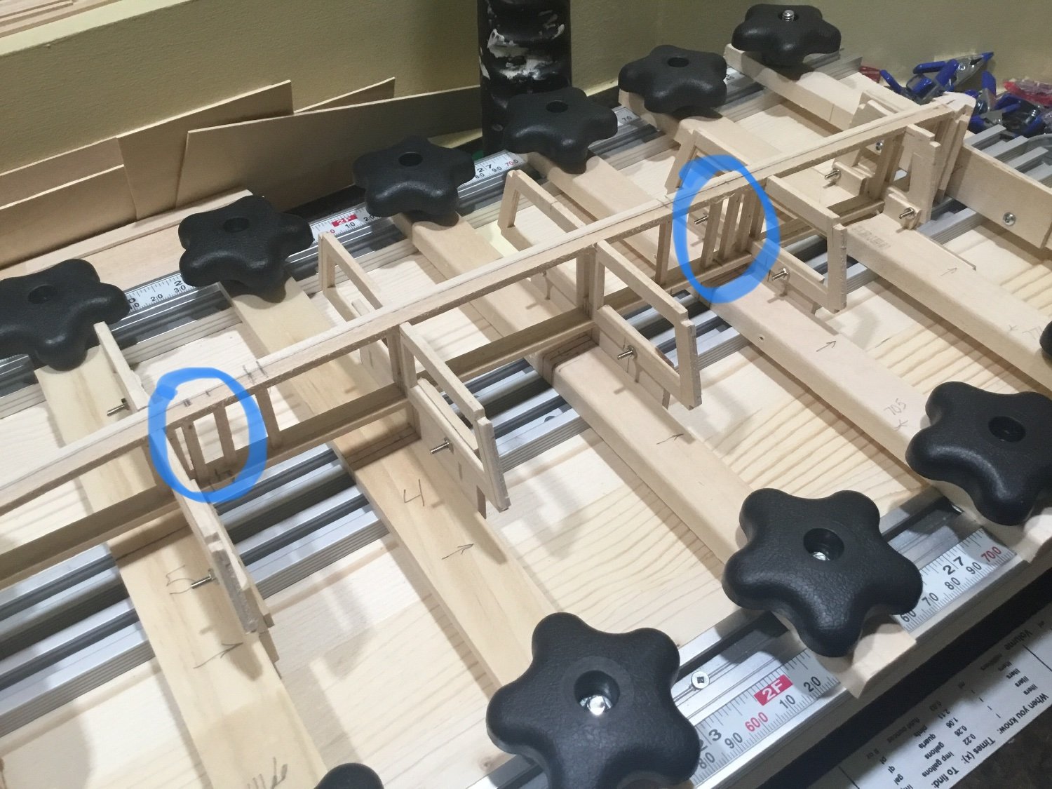
Once the center strips of the keelson and king plank were attached, vertical supports were added for the masts and bulkheads for the trunk, cockpit and hatches. Then the outer strips were added and more vertical supports were added so that the whole structure is 3/8” thick.

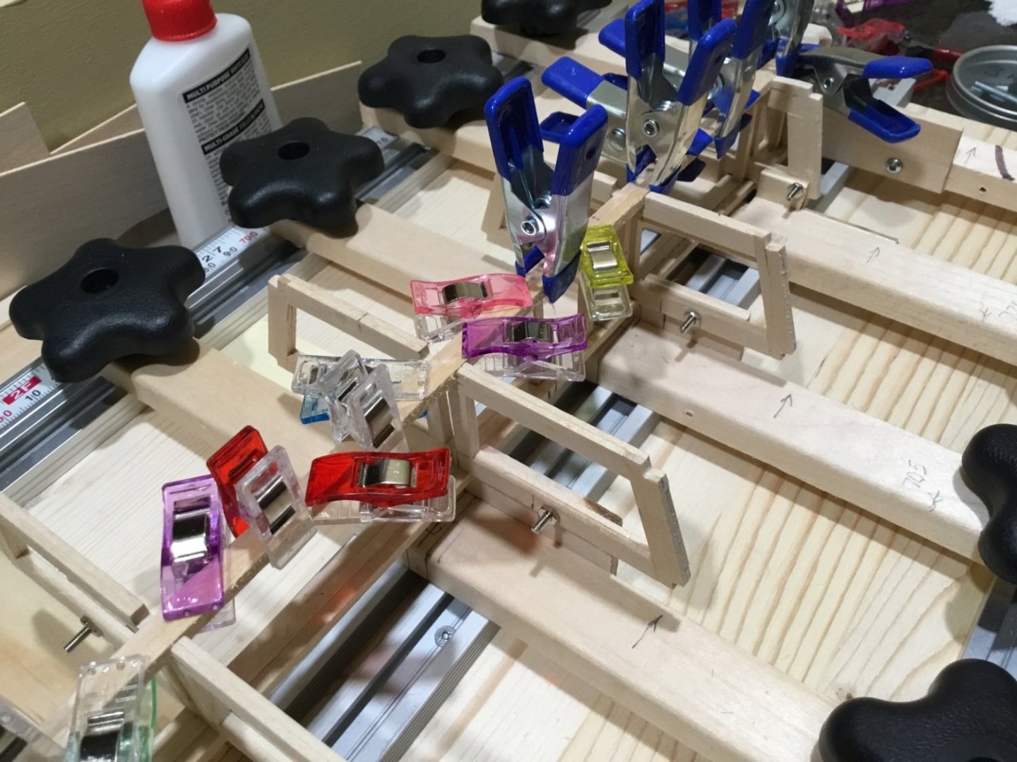
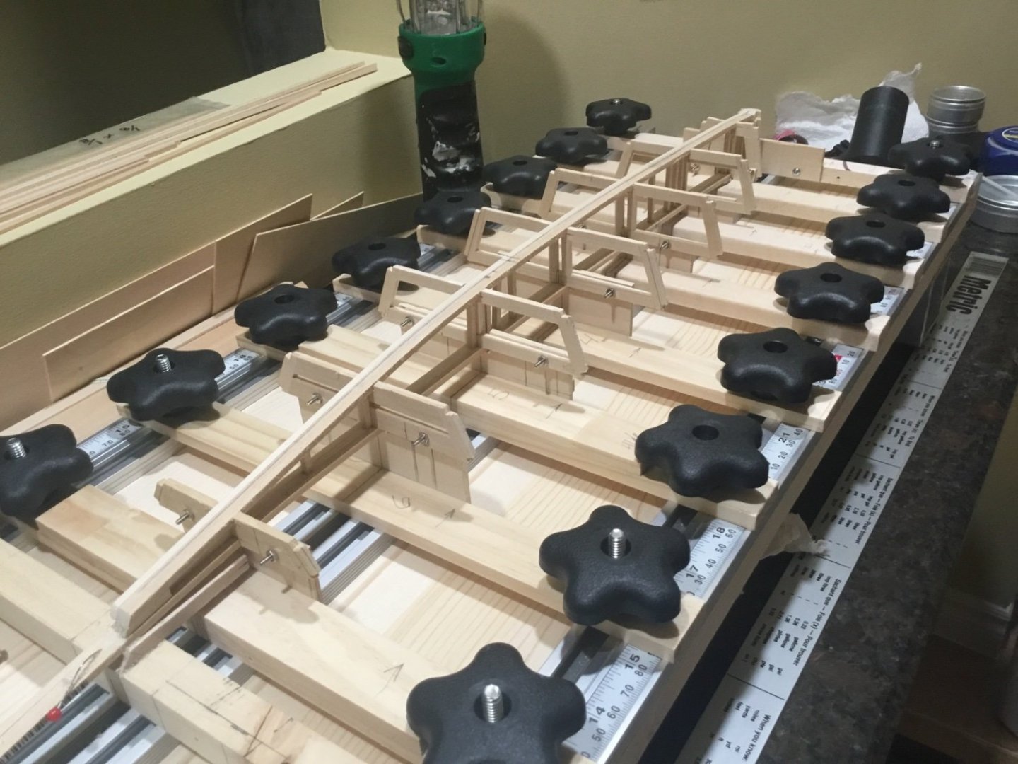
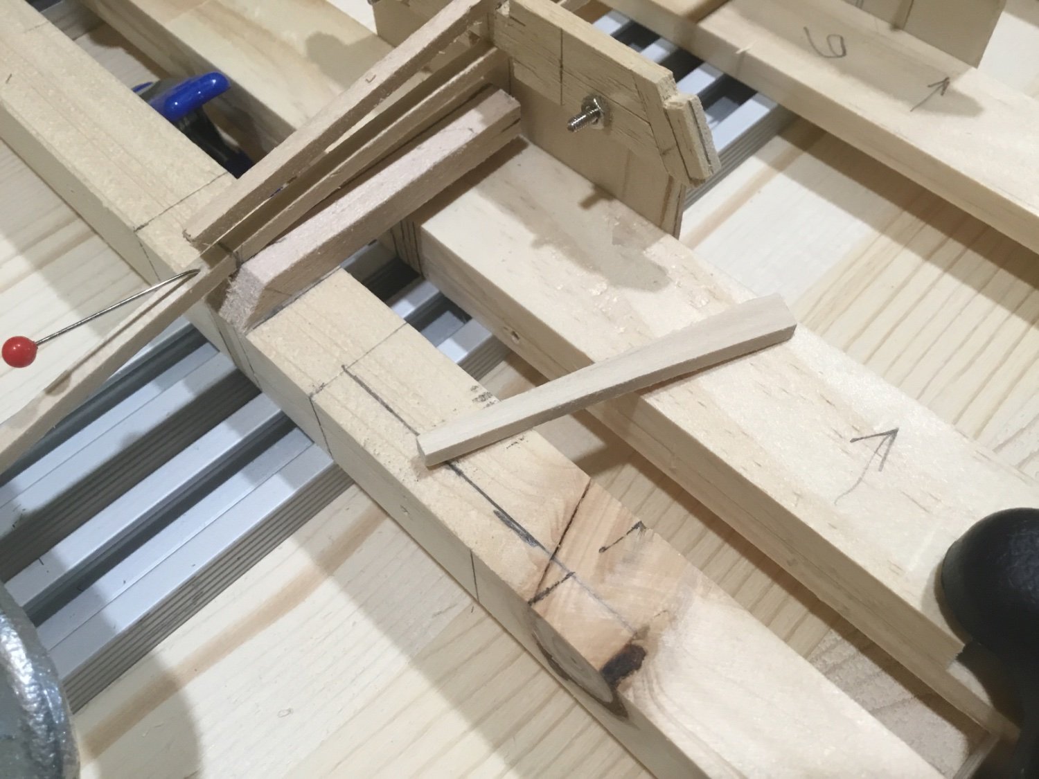
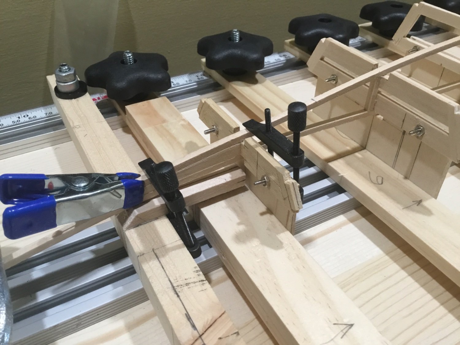
The two areas where the masts will be stepped are built out so that they are 1/4” square and then boxed.
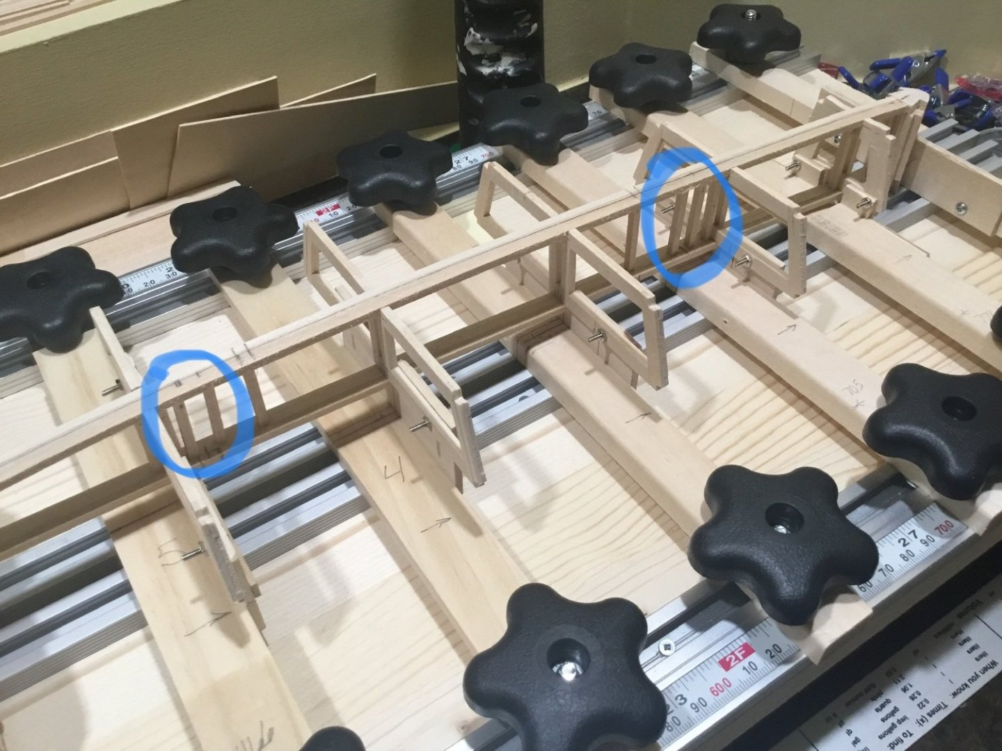
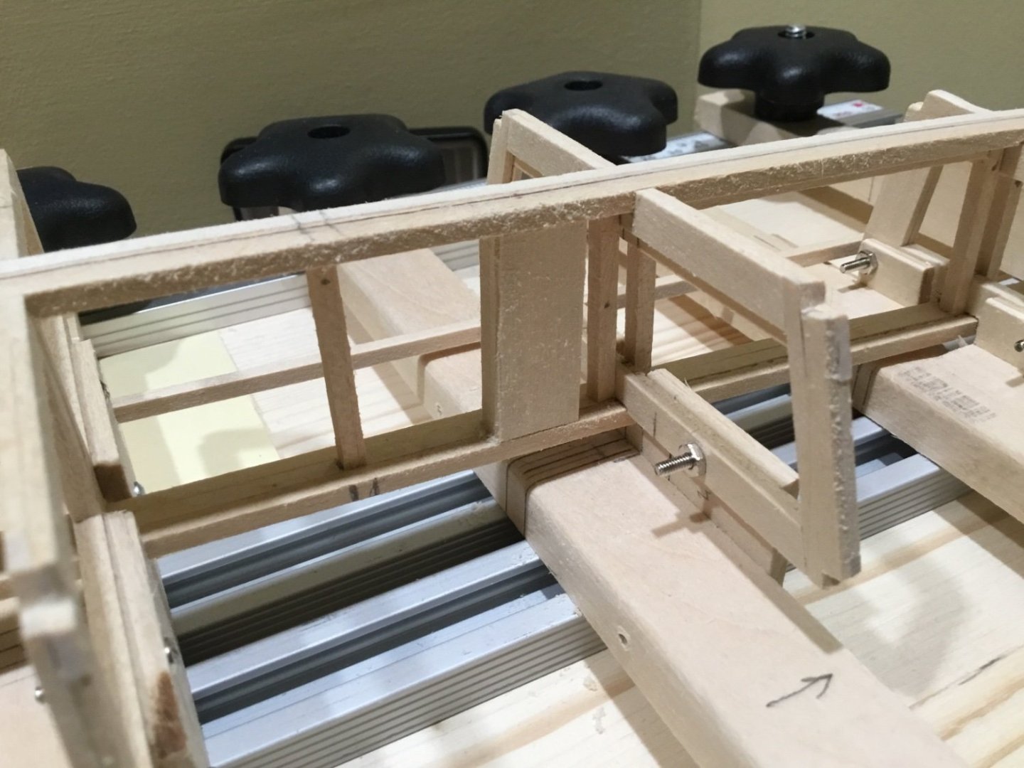
The plan is to box in the entire bulkhead former and then add lateral supports for the frames before attaching the chine logs. Hope to see you soon.
-
Hi Rick, in the first photo where you are using the t-pin, the batten seems to cut straight across the space between the bow filler and bulkhead M. Maybe you can try putting some bend in the end of the batten so that it will enter the rabbet at the stem at a better angle. Then see how it sits moving aft. Looking good!
-
Tim, congratulations on finishing your dory. Your dory and build log are excellent. Looking forward to your next build!
- Ryland Craze and East Ender
-
2
-
Hi rudybob, here’s a few pics of some of my planking. I found it easier to lay out the garboard but using a straight strip of wood clipped to the bulkheads where the plank above the garboard would sit. Start at the joint and run it back to the stern keeping the distance from the keel not more than the width of the plank you are using for the garboard. Mark the bulkheads and use the measurements at each bulkhead to lay out your garboard. Yours won’t be as wide at the stern (as in the first pic) but the principle is the same.
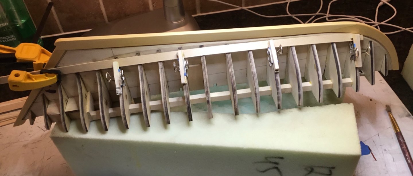
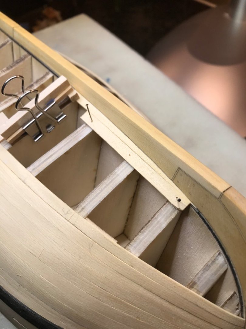
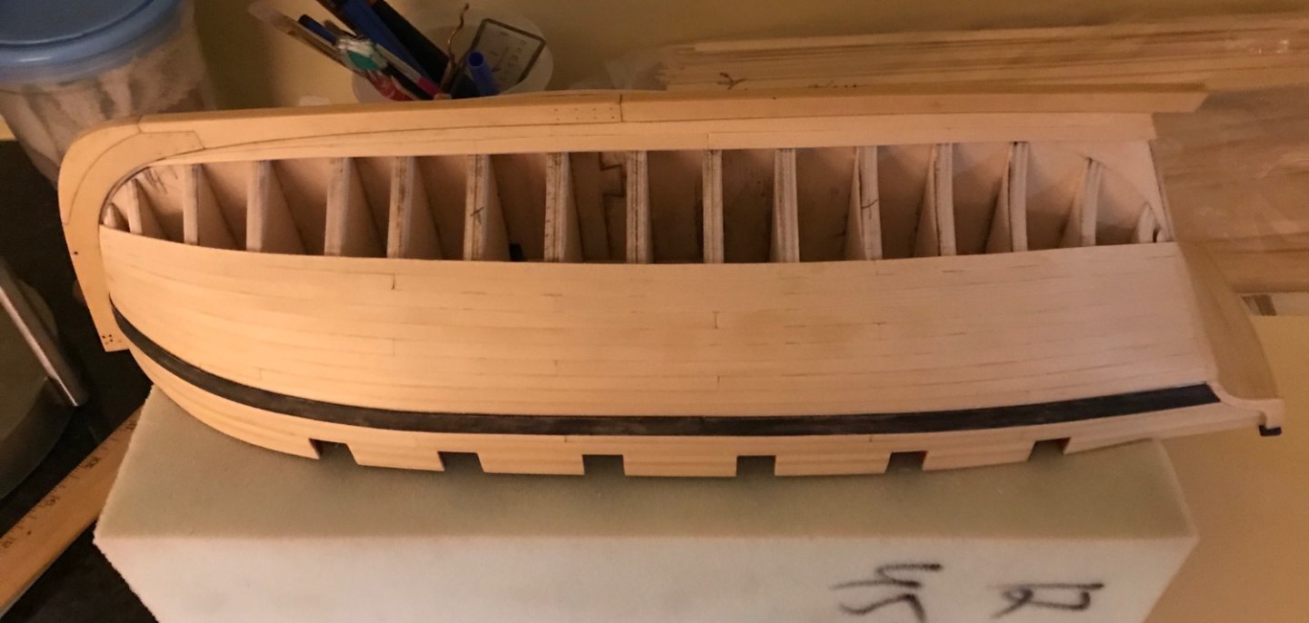
These aren’t the best examples but they give you an idea of what Allen suggesting.
- rudybob, mtaylor and Knocklouder
-
3
-
Coming along very nicely Glenn. 👍
- Glenn-UK, hollowneck and mtaylor
-
2
-
 1
1
-
Hi Wizard, your pram is looking really good. To cut the brass tube, try sliding a piece of 1/32” brass rod inside the 1/16” brass tube to keep it from crushing and use a razor knife to cut it. Roll the tube back and forth under the knife blade. Annealing will make it easier but you can try it without annealing. That’s a nice looking red. What color is that? Hey Bryan, we were answering at the same time. Good suggestion 😀
-
-
Hi rudybob, as you approach the stem, the planks will become narrower. How much narrower depends on the vessel you are modeling. It doesn’t matter whether you have spiled the plank or whether you have tapered and edge bent the plank, its width will still have to change. So my answer to your question is no, that is not true.
-
Hi dodgeyhack, your fairing looks very nice. You might want to do a little trimming and re-fairing where bulkheads 14 and 16 meet the bearding line. Good luck with your build!
- Ryland Craze, Chuck, mtaylor and 1 other
-
4
-
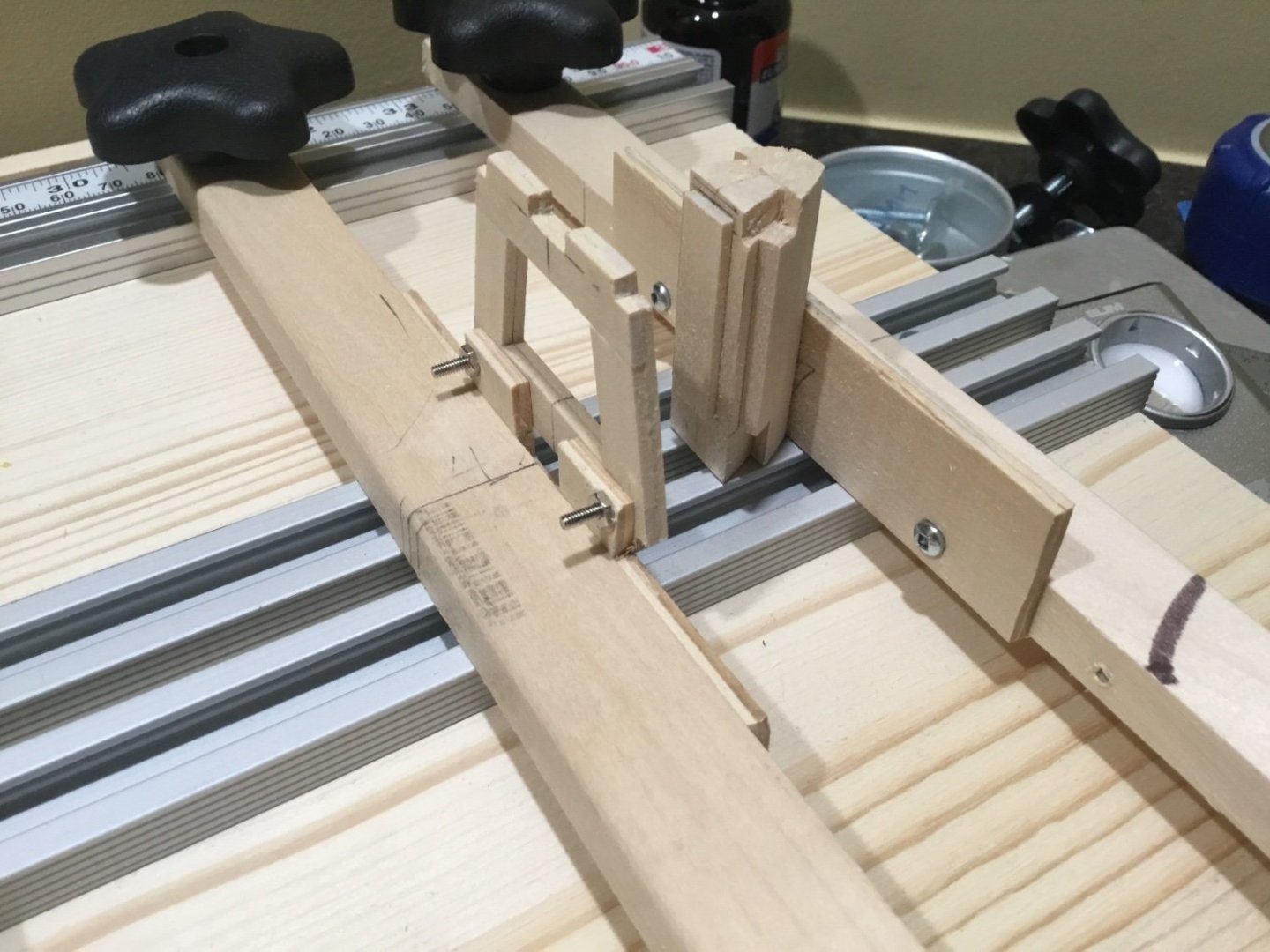
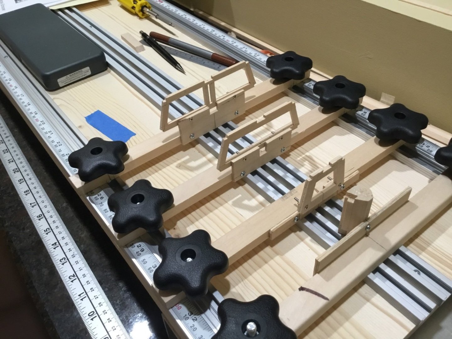
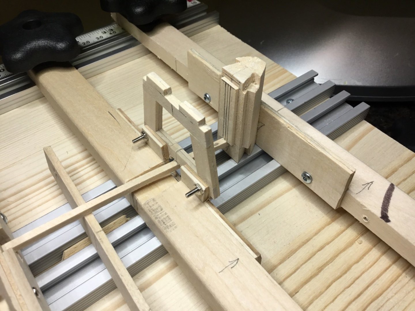
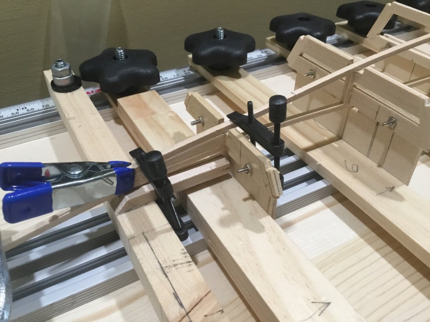
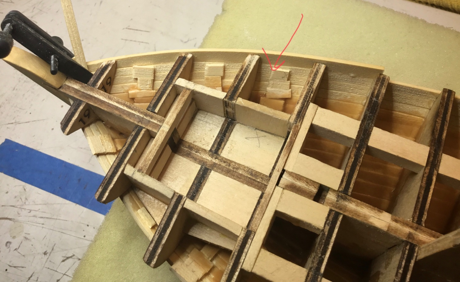
Hey Everyone, there’s been some planking questions come up lately so I thought I’d add this suggestion to this thread. Lots of people probably do this but it’s good to renew tips every once in a while. Instead of adding filler blocks or extra bulkheads I’ve been gluing small pieces of scrap wood to the previous plank in difficult areas like the bow or stern to keep the planks on the same plane. The next plank can be glued and clamped at this point effectively giving you an extra bulkhead. Also not a bad idea to add them in straight areas where the bulkheads may be over 2” apart. Should add though that the planks will still need to be tapered and bent first.

- GrandpaPhil, mtaylor, Baker and 3 others
-
6
-
-
Vladimir, great comeback and beautiful pictures!
-
Melissa, congratulations on finishing your journey. Your Statenjacht looks fantastic.
- Ryland Craze, Keith Black, Baker and 1 other
-
4
-
Vladimir, sorry to see this happen. Won’t be long, she’ll be just like new.
-
Hi Dave, you have gotten a lot of very good advice. Like you, I am also using darkened annealed wire to make rings and eyebolts although not at such a small scale. I’ve been getting away without soldering or gluing because nothing I’ve done is under tension. (Cannon rigging) The nice thing about annealed wire is that you can burn off the coating with a micro torch if it becomes scratched while working it and you end up with a dark grey flat finish. I belong to the group that believes you should do as little as possible to get the results that you are happy with 😀
-
-
Very nice Eric, we used to grow climbing beans on a similar structure. They were finished producing just when you wanted to have the sun warming you up again. Of course our climates might be a little different.
- Canute, Keith Black, mtaylor and 1 other
-
4
-
Hi Panteg, I think there should be a strip of Obechi 3 x 8 x 300mm included in the kit that is probably cut in half to use for the stand. Good luck with your build
-
Hi nemosdogs1, welcome to the forum. Make sure you head on over to the new members thread and introduce yourself. The numbers inside the circles on the drawing you are showing will also be on another drawing showing the sails and rigging. I think Billings calls this drawing “General Arrangements”. The corresponding number inside a circle will be pointing at the rigging that attaches to the pin or cleat shown on your drawing. Sometimes they are printed very lightly and are hard to see. Good luck with your build.
- Keith Black and Baker
-
2
-
9 hours ago, BobG said:
Spectacular model, Paul, well done!
7 hours ago, Dave_E said:Outstanding Paul! 👍😀
Hi Bob, hi Dave. Thank you for your comments. You are both very kind


Oseberg and Kraken by Glen McGuire - FINISHED - Bottle - 1/250
in - Subjects built Up to and including 1500 AD
Posted
Glen, congratulations on finishing your incredible Oseberg / Kraken. This build has given many people lots of smiles. Thank you