allanyed
-
Posts
8,149 -
Joined
-
Last visited
Content Type
Profiles
Forums
Gallery
Events
Everything posted by allanyed
-
 Just happened onto your build log Joe and wanted to say what a beautiful build. Hitting the like button was just not enough. As a fan of these fishing schooners, it is nice seeing one of the best. Allan
- 140 replies
-
- 3
-

-
- benjamin w latham
- model shipways
- (and 1 more)
-
Thanks Spyglass. Overall, I think we are both on the same page. I have found that properly shaped planks hold fine within 30 seconds most of the time, and always within a minute using the "yellow" version of PVA. It all comes down to making sure the planks are pre-bent and have no spring in them. Allan
-
In the end, whatever works for each person is the best way to go, but based on experience of quite a few builders at MSW, if the planks are tapered and spiled or pre-formed using the method Chuck Passaro has described, there really is no need for any clamps or rubber bands. Carpenters' glue and finger pressure for about 30-60 seconds is really all that is needed. Any kind of clamp presents the danger of denting the planks, even if using a piece of scrap between the clamp and the plank. Just one more opinion based on trial and error over the years. Allan
-
Juhu, I just sent an email to Bristol Marine asking about this as they are rebuilding the Effie M. Morrissey 1894. A member here, Jond, visits their yard regularly as he is building a model of Effie (renamed Ernestina) and may already have an answer as well. Will let you know what I hear back from their yard. Allan
-
Jim Byrnes Thickness Sander
allanyed replied to Roger Pellett's topic in Modeling tools and Workshop Equipment
Jaager, You are correct. I failed to mention I "smooth" sand the surfaces to be seen and not glued. Great catch on your part! Allan -
MicroMark Titanium Chisels
allanyed replied to josh0526's topic in Modeling tools and Workshop Equipment
Josh, If you are going to buy a quality set of chisels and spend this kind of money, you will find rave reviews from many members here, including me, for the chisels from Mihail Kirsanov. If these are of interest PM me and I can forward his direct email as it is not a good idea to put an email address in these posts per recommendations from the moderators. Allan -
Jim Byrnes Thickness Sander
allanyed replied to Roger Pellett's topic in Modeling tools and Workshop Equipment
Roger, I have been using the Byrnes sander for many years. If he had serial numbers on them (maybe there is one on there somewhere) mine is probably in the number 10 to 20 range. I have never had an issue with tipping. It weighs a lot and as said above, the main thing is to not take off too much wood at once. I stand to the side just in case a piece does launch and cannot catch me, but rather connects with the concrete wall. Once of my favorite things about this sander is that I have a rough paper on one half of the drum and finishing (400 grit) on the other side. Allan -
Welcome to MSW!!! I hope to see more of your build and suggest you start a build log. You will receive good advice when and if you run into any build problems. Have a good day, I know from personal experience within our family the effects of PTSD and some days and nights are better than others. I hope making new friends here will give you more good days! Allan
-
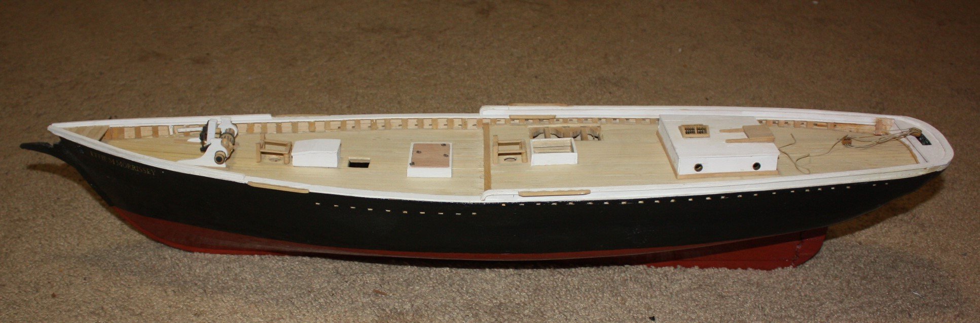
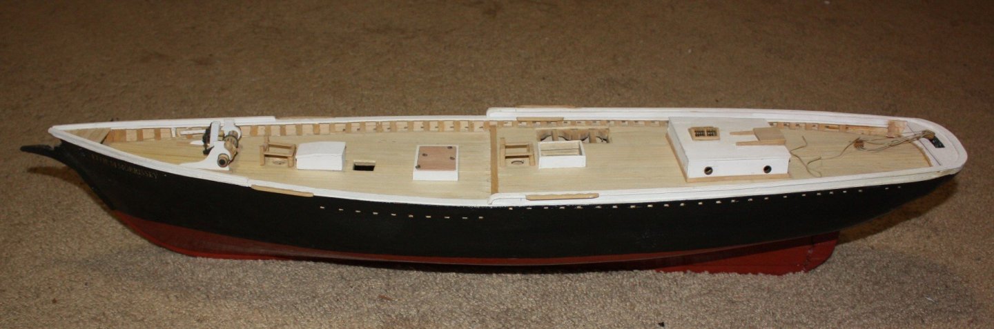
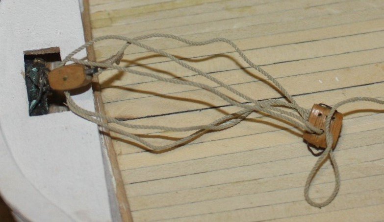
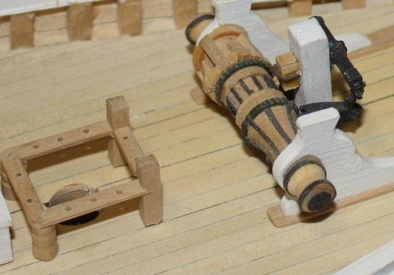
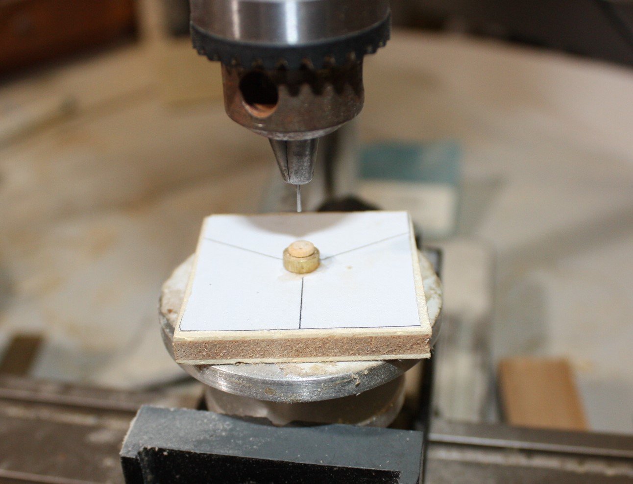
So more than seven years have gone by since starting this model of the Ernestina/Effie M. Morrissey and it is now back on the work bench. The hull was completed about early 2014 along with much of the deck furniture then set aside as another project came up. Now that she has a buyer it is again a work in progress. I began making the deadeyes the past few days. Using the drawings from the Library of Congress they are between 0.16 and 0.17" diameter at scale. I have a drill bit that is 0.17 so began making them at this diameter. I made a jig with a brass ring with an ID of 0.17 and a table with lines 120 degrees apart I had a small rotary table that I made quite a few years ago and set this up for drilling. The ring was epoxied to the square table and left to cure overnight before using it. Using epoxy instead of CA gave some time to move the ring to get it perfectly centered on the three lines. The eyes were turned on the lathe to 0.17 diameter using castello box wood. These were then inserted into the brass ring. The drill bit was set in the chuck with just enough exposed to clear the deadeye. This prevented the bit from wandering so predrilling a pilot hole or punching a starter hole was unnecessary. Once I made 30 eyes (6 more than needed, just in case) they went into the tumbler for 20 seconds to round off the edges and it also took the diameter down to 0.168, so within a thousandth or two of the diameter on the drawings. I now have 27 eyes to work with as one is somewhere on the floor hiding and two had the holes quite a bit out of synch with each other even using the jig. If I ever get myself a mill and rotary table the drilling should be more exact and consistent. The first photos show the hull today, boom buffer and rigging, windless. The last is the deadeye jig set up on the mini drill press. Allan
- 86 replies
-
- 15
-
-
- schooner
- effie m morrisey
- (and 1 more)
-
Backstay deadeyes fastening on deck
allanyed replied to Michelnou's topic in Masting, rigging and sails
Mike, As usual, photos would likely get you more responses. Are you sure the backstays would go to the deck and not to the cap rail or channel? If to the channel, deadeyes could be the way to go, but if to the cap rail, a pair of single blocks seems to be the rigging on plans I have looked at. Allan -
Hi Kathy, Glad to see you took the plunge into the dark side of scratch building! For a first attempt you chose a pretty complex project and did a lovely job of it. For the future, you may want to consider the blocks, if building a model of ship from the late 19th century onwards, as there were internally stropped blocks as you show in the actual ship photos. These can be tricky to make from scratch , but the ones you can get from Syren and assemble yourself are quite good and represent this type of block very well. I look forward to your next project and hope you start a build log so we can follow along as you progress. Allan
-
Bill, You had asked about books on rigging. My suggestion is volume four of The Fully Framed Model as it deals with rigging a model. There are several books on contemporary rigging of actual ships that I use a lot, but these do not give the "how to" information you are seeking. Allan
-
Contemporary guide to decorations on ships, 1711
allanyed replied to bruce d's topic in Nautical/Naval History
As Wayne said, each page can be saved from the link above and a book put together. If one wants it in printed form rather than reading on the computer, it is cheaper to buy the book for about $25 for hardcover and a tad less for paperback rather than burning up ink and paper at home. Not to confuse Echo with Ecco, but the print size in the Ecco (Eighteenth Century Collections Online) copy that I have is sufficiently large for my old eyes but there may be versions out there that are not so good as Wayne kindly points out. The plates are indeed on the smaller side as they are not fold outs. Allan -
Going back to your list from February, if you are still in the hunt, did you contact Turquoise Yachts in Turkey asking about getting plan or at least lines for Amphitrite which was owned by Johnny Depp and then Rowling before she put it up for sale again. If you explain your project they may send you the information you need. Better still, call them. I did this back in the late 70's and of course it was snail mail or phone back then. I was able to acquire sets of plans from both Islander Yachts and Californian Yachts, just giving written assurance that it was for making a model and the plans were not to be copied, shared, etc. etc. Allan
-
Keith, If your skills in cooking are half as good as your modeling skills, I hope you don't mind that I am inviting myself over for dinner the next time I am near Sussex!!! I know it is off topic, but do you have any specialties? I love cooking, (about twice a month,) and one of my favorites is making pasta with mussels, clams, and shrimp. I always use DeCecco and lately I have been able to find it with the boxes marked that it is from bronze dies. Makes for a rougher texture than stainless steel thus holds the sauce better. At least that is what my coworkers in Italy always told me. I little (or more than a little) wine, some in the sauce, the rest in our glasses and it is a good night. Back to business, how did you slice each rail so cleanly and evenly once the brass inserts were in place? What kind of glue did you use with the press fit? Thanks!! Allan
-
Eberhard, You have kindly pointed out the obvious which I failed to notice. What you wrote makes a lot of sense. I checked on the architect's drawings and the gaff indeed has 6 inches clearance should it lie perfectly horizontal. Thank you very much!! Allan
-
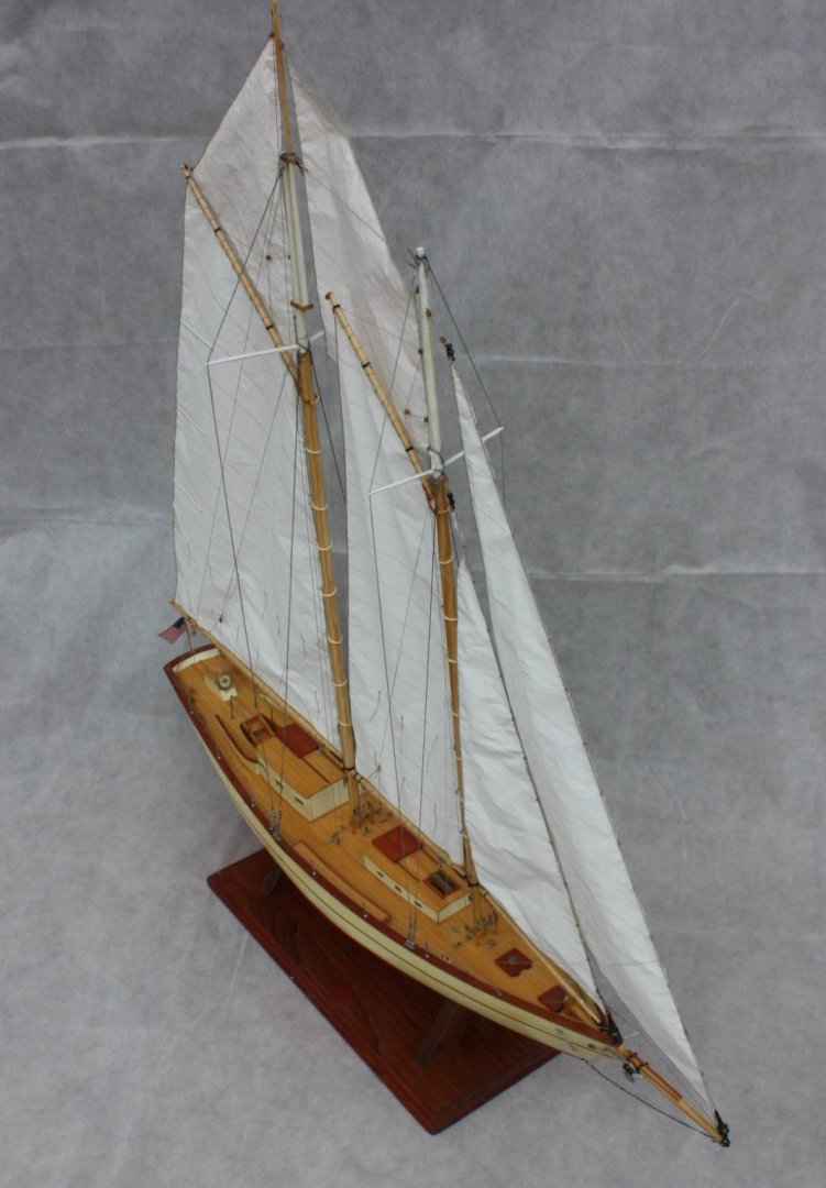
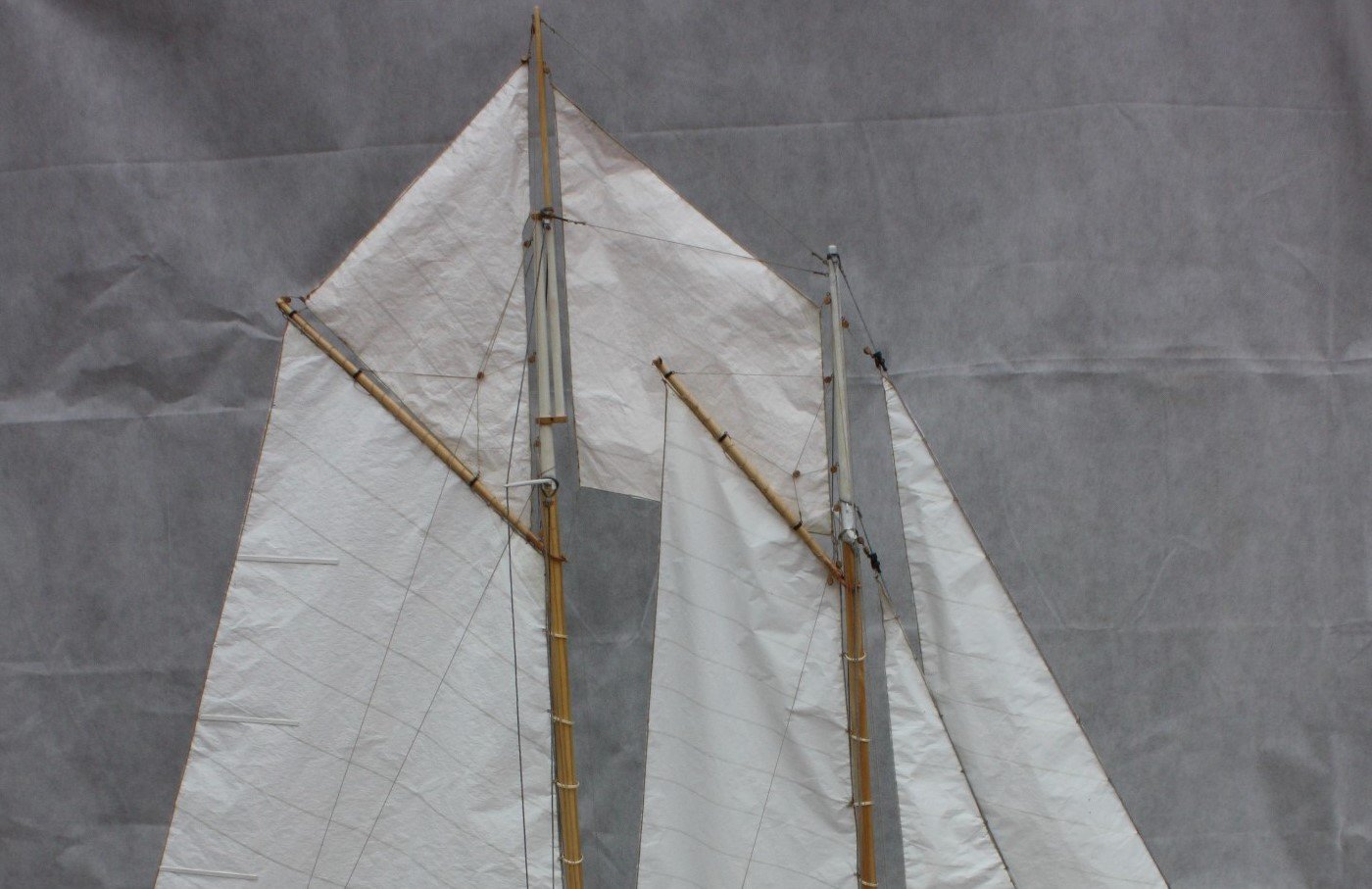
Sails are rigged and guard rails are installed. For the rail wire I used rope soaked in chrome paint except for the entry area which is rope hooked to the stanchions. I have a few more rope coils to make and glue in place, otherwise ready to ship. Note in the second photo it is clear that there is a pretty large gap (4 feet) between the upper aft side of the fore sail and main mast. The gap on the model is actually a tad smaller than shown on the sail plan. I have no idea if this gap is to aid in sail handling when tacking and so forth or for some other reason. Perhaps it has something to do with allowing the wind to leave the aft side of the foresail without crossing over and directly onto the main sail and creating eddies or some other disturbance with the wind already coming directly on the main sail. I would love to hear from anyone that knows why this gap would be so large. I see this same gap on every sail plan of the schooners in Chapelle's American Fishing Schooners so I am sure the design is correct, but would like to know the reasoning. Even if the foresail extended back another 2 feet or more, there would be a lot of clearance to swing the boom and gaff to port or starboard once the fisherman's sail was down. Allan
-
Hi Phil, The rub-ons I was referring to are lacquer dry transfer type, about 25-50 microns (0.000025" -0.000050") thick. Is this the type you used or some other? The following is from an article I found on dry transfer lettering. Unlike vinyl lettering, dry transfer images and type looks as though they are printed directly on the surface – and they perform equally well on glass, wood, metal and plastic. With dry transfers, there is no edge and they are smooth to the touch. It means that the transfers you receive of your artwork are only the thickness of the lacquer ink. Lacquer adhesive is only on the image area so once applied there is no adhesive outline or residue. Especially important to note is that dry transfers can be made permanent with a clear spray coat of lacquer or workable fixative applied on top. From what I have been able to find so far, if the name was on the ship at all, the letters were only painted on, they were never made of wood or metal. Allan
-
Congratulations on your authoring the series. I will be ordering the first one as soon as I am done with the books I am currently reading now. Allan
-
Mast Tackle top - Revenge 1577
allanyed replied to Jonathan_219's topic in Masting, rigging and sails
Hi Jonathon, I agree with Henry's description as it is the same description that Lees wrote in the Masting and Rigging English Ships of War which is also my #1 go-to for rigging information for British ships in the time line he covers. But in some cases the pendants of the tackles may have been cut spliced with one length running down each side. (Longridge - The Anatomy of Nelson's Ships, page 213). Same was done for the burton pendants on the mizen. If having to choose one or the other I would go with Lee's description, but it may help if you would let us know what vessel you are building to be sure. From the picture on the right it looks to be pre-18th century. Allan -
Mark There was likely no nameplate, but rather the name would have been painted directly on the stern if it was there at all. Not that the Americans followed what the British did, but the British began painting the names of the ship on the stern by order in September, 1772 some few years after Virginia was launched. They stopped putting the names on the ships after 10 years as they felt it was giving the enemy information unnecessarily . Again I don't know if the Americans followed the British practice, so if you do go with putting the letters on, rub on letters are a great way to go but be sure to make a template on paper and print the name on this template. Hold it to the stern to be sure that the curves of the stern do not wind up having the letters cup, but rather go straight across or arc slightly. Once it is correct, the template can be used as a guide for placing the final lettering directly onto the stern. ASIDE--I looked at your URL. Did you write the Oscar Jade series? Allan
-
I prefer hardening the end of the line and then cutting it to a point with a scalpel whenever possible, but sometimes the needle threader is the easier way to go in tight areas or other items such as blocks or sheaves. The only problem with the needle threader is that you are pulling a folded-over piece of line, thus double the diameter through a hole meant for one diameter if it is sized correctly. The line will compress somewhat but threaders are not always the strongest. I pinch down the plate to be sure the wire is tight then add a dab of CA so it is less likely to pull apart. If the line comes through the deadeye hole very easily with the threader, the hole was too big or the rope too small 😄 Allan
-
Stitching sails with sewing machine
allanyed replied to Jorge Hedges's topic in Masting, rigging and sails
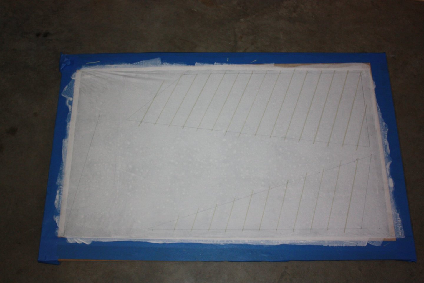
Jorge, Yes there is a frame and a matching plug that fits inside the frame. First I took the dry silkspan and cut it to fit just inside the outer edge of the frame. While it is laying on the frame and plug I wetted the silkspan with a water (brush or spray bottle works fine) Then I pulled the short edge on one side so there were no big wrinkles and taped it to the frame. Then I did an adjacent side, again pulling the wet material a little bit to get out big wrinkles and taping it to the frame. Then did the same with the remaining two sides. After it is taped I picked the frame with the material up to get it off the plug. I set it on blocks to dry as the sail material sags a bit. Once it is dry, it shrinks and is very tight. There is no need to try to pull it too tight while wet as it will tighten up on its own. Once it was dry I painted it. It will sag again at this point. This can be done carefully without the frame going back on the plug or with the plug in. If with the plug in, be sure to carefully remove the frame and painted material as soon as the paint is on so it does not dry to the plug. The plug will have paint on it if inserted during the painting, but I found this was not a problem once removed and left to dry while the frame with painted material were drying. Once the paint is dry, the material will be tight again. I then reinserted the frame on to the plug for the next steps of drawing the sails, doing the seams, etc. You can find a lot more details in David Antscherl's booklet on sail making which is available at SeaWatch books for $7. Hope this helps. Allan -
Mark, Darkened seams only go where there was caulking between the pieces to prevent water seeping through the joint and causing rot and/or leaks. It is not so much a matter of personal choice, but what worked back in the day if you are trying to simulate actual practice. Allan
-
Stitching sails with sewing machine
allanyed replied to Jorge Hedges's topic in Masting, rigging and sails
Jorege, Be careful with white glue as it is water soluble. If this was only a test, I suggest you try using matte medium. It will not dissolve if wet with water and dries clear, plus is less viscous than white glue so there is no worry of bumps and spots that may stand out. Sewing will be totally out of scale and not look realistic. At our scale you would be hard pressed to see a sewn line if it were to scale, which is not possible. Remember that there are seams for each panel and the edge of the sail prior to putting on the boltrope, not just a sewing line. The first photo below is one of several posted in the Boothbay 65 build log last week with additional explanations on sail making. In place of sewing, consider using a marker pen such as Liquitex which comes in many shades. I used a 2mm pen but if your lines need to be narrower, the tip can be cut smaller with a scalpel blade before charging the pen the first time. I also happened to give a thinned coat of titanium white artist acrylic after the seams were drawn to make them more subtle. Examples of before and after panel or edge lines are in the second photo below. David Antscherl recommends making seams, which should be about 2" wide (real world), with thinned paint to match closely to the sail cloth using a bow pen. Allan