


allanyed
-
Posts
8,149 -
Joined
-
Last visited
Content Type
Profiles
Forums
Gallery
Events
Everything posted by allanyed
-

SOLEIL ROYAL 1669 by michel saunier
allanyed replied to michel saunier's topic in - Build logs for subjects built 1501 - 1750
Hi Michel I just joined your fan club and congratulate your professional work. I look forward to seeing your work continue in such spectacular fashion. I love the lost wax cast cannon, especially the cascabels! Allan -
Pandora by marsalv - FINISHED - 1:52
allanyed replied to marsalv's topic in - Build logs for subjects built 1751 - 1800
TOP WORK The gear and ratchet teeth on the elm pumps are the kinds of details that make your build so exceptional. I cannot tell from the photo but are the "iron" parts made of brass or some other material. Cutting the gear had to be a challenge and if you have more details on that, it would be great to see. Allan -
Bowsprit shrouds and eye bolts in the deck...
allanyed replied to M.R.Field's topic in Masting, rigging and sails
The best I could find on the internet about turnbuckles are quotes calling them out from about 1850. Were they prevalent in usage on yachts, I have no idea. Allan -
Bowsprit shrouds and eye bolts in the deck...
allanyed replied to M.R.Field's topic in Masting, rigging and sails
Martin Here is a page that may help. I have no idea why it flips when I attach it here as it is right side up on my file page. What does that line in the eyebolt go to? Years ago I had a chance to sail on a number of boats from monomoys to Weatherly but never saw anything like this. Allan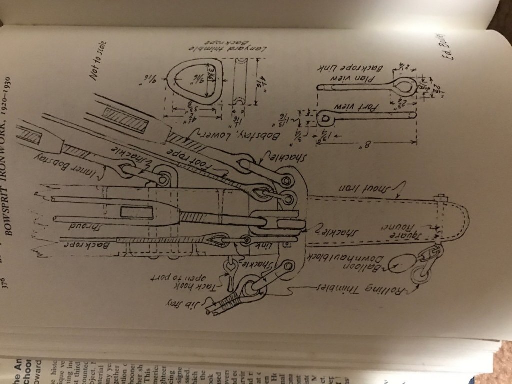
-
Bowsprit shrouds and eye bolts in the deck...
allanyed replied to M.R.Field's topic in Masting, rigging and sails
The eye bolts in the deck could be for fairleads or blocks. I am not sure exactly where these are when you say in the middle of the deck. I would post photos of the pages from Chapelle, but I am not sure if that would be a copyright violation so err on the side of caution. The chain plates would be about 3 1/2" wide and probably 26" to 32" long. They would be 1/2" thick and have a 1/4" bevel all around and let into the planking to the bevel. For the model, I woud make it 1/4" thick and bolt to the planking without letting it into the planking. Again this is all about schooners and such, late 19th and early 20th century. For a Victorian cutter, if it is the Vanity 1885, this information is probably reasonably accurate. Allan -
Thanks Ed, Just took a look at their site and they do appear to have some really nice items that are otherwise difficult to find. I was really hoping for something like this versus you having made the chain yourself! Allan
- 3,618 replies
-
- 3
-

-
- young america
- clipper
- (and 1 more)
-
Bowsprit shrouds and eye bolts in the deck...
allanyed replied to M.R.Field's topic in Masting, rigging and sails
Martin Yacht is pretty generic, so do you have a more specific vessel in mind? The only description I can find in the book Sailing, Seamanship and Yacht Construction by Uffa Fox gives a description for the ketch rigged yacht Landfall. This is pretty much the same as described in Chappele's American Schooner (page 376 gives a nice drawing showing this) Typically the aft end of the shroud is attached to the hull with a thimble and shackle to an eye bolt which goes through a chain plate. The length of the chain plate on each side was usually determined by the spacing of the frames. The forward end at the sprit itself is a turnbuckle shackled to an eye band that goes around the sprit. This band has ears with the holes to accommodate the shackles of the shrouds on the sides, fore stay on top, and bobstays below. Hope this helps. Allan -
Ed Catching up on your log and still amazed! I just went back looking to see if you mentioned the chain you used and cannot find anything so my apologies if you already addressed this. Where did you get the stud link chain? Thanks Allan
- 3,618 replies
-
- 3
-
-
- young america
- clipper
- (and 1 more)
-
Rick, Just found your log and went through it as I have always enjoyed the looks of any schooner, including topsail schooners. Well done. One note, and I hope you don't mind me bringing it up, but the drawings you show are pretty clear that the hinge plates for the rudder extend nearly to the aft edge of the rudder and further forward on the sternpost compared to what is shown on the model. It sort of stands out (probably only to me) and maybe could be corrected easily enough with new hinge pieces. Allan
-
Frank You are presenting a perfect example of how a relatively "simple" vessel can be a masterpiece of construction. A skipjack like this could be a great project for a first time scratcher as well as a more experienced modeler interested in these oyster boats. Yours would be a beautiful addition to the museum or Theo's or some other restaurant or high spot at St. Michaels or Tilghman Island. Great build log! Allan
-
In reading the Thomas Kydd series of books, there are a number of references to "pointing" the ends of running rigging lines at times instead of adding a whipping to the ends, which was a new one for me. I see this as a practical thing for reeving lines for our modeling practices. I was just wondering if anyone else is familiar with this practice and how common it was. Allan
- 1 reply
-
- 1
-
-
rigging sizes and proportions in Lees
allanyed replied to hamilton's topic in Masting, rigging and sails
Hamilton At least for the British ships, back in the day, circumference was the predominant measurement. At some point, rope of 1" diameter or less was measured in diameter not circumference. Today, breaking strength is a commonly used specification as there are so many more materials available to make rope. Practically, it is easier to measure the circumference than the diameter, so that may be the reason circumference was the commonly used dimension. For our model rigging, it is easier to measure the diameter with a micrometer than some how accurately measure the circumference. Allan -
Rigging Question (Probably first of many!)
allanyed replied to Bluto 1790's topic in Masting, rigging and sails
Jim, I have found Lees to be reliable and informative to the extreme. Petersson, not as much, and unless you are building a 36 from about 1785 rather than Leopard, it will not have all the information you need. Try to figure out a line size from Petersson, (he gives no information) then look at Lees. If you need details on "how to" for many things, get David Antscherl's TFFM volume 4. As far as scratch building being for the advanced builder, I do not agree. One of the biggest problems for many that makes scratching difficult is the lack of a bigger work space and the larger set of tools needed when compared to assembling pre-made pieces from a kit. That in itself makes it a great thing to have kits available. There is always the compromise where you can scratch build part and get some fantastic parts and materials from various sources that advertise right here at MSW. Allan -
Brett Have you looked at any planking expansion drawings? There are several that can be found at the NMM collections site. One of the most clear without purchasing a set is of Squirrel 1785. You can see the scale at the bottom of the drawings and make out the garboard plank quite easily to get an idea of where it ends and compare to the profile and frame disposition drawings. Allan
-
Welcome Good luck with your builds, you will find all the help you need from the team here at MSW. If you please, let us know a name by which we can address you, if not Zarkon, the ruthless and overbearing ruler of the Galra Empire Allan
-
Don, Have you thought of forgoing the plywood false deck altogether and just plank the deck as it is done on other models and the real vessel? You may have to use planks that are a bit thicker to account for the thickness of the plywood. Allan
-
Painting Wales
allanyed replied to JohnB40's topic in Painting, finishing and weathering products and techniques
A little too late, but for the next time. For unsealed wood, India Ink or a dye is good substitute for paint. Even black marker works very well. It penetrates and leaves no brush marks, and any finish can be used over it. Allan -
Yes understood, but the coating would be black on the brass. Just an idea from days of old when they coated the iron cannon with this mixture. Surely paint is easier Allan
-
When doing multiple pieces, you would need solders with different melt points, starting with the highest melt point solder first. The next piece to be soldered on the assembly would use a lower melt point paste, and so forth. I have not tried more than three solder temperatures and like everything else, it still takes some practice to get a feel for this, but it does work well. Allan
-
Eddie, I did some digging but did not find anything concrete in any books or tables regarding how many pieces, lengths, or location and types of the joints. Logic says the longest pieces would be similar to that of the planking, perhaps 20 to 30 feet. In order to keep the grain as straight as possible, the forward most pieces would likely be shorter to accommodate the hard curve without too much cross grain. A hooked or perhaps a plain scarph seems appropriate for the joints. This is all conjecture on my part. Allan
-
I have no idea if this would work on brass cannon, but could be interesting to try bees wax, turpentine and black pigment powder (like lamp black) as was done on the actual barrels back in the day. I doubt it would be better than blackening, paint, or other options we have today, but if it works, it would lend an air of authenticity and give a bit of a conversation piece. Allan
-
Bending with steam easily
allanyed replied to a topic in Building, Framing, Planking and plating a ships hull and deck
John You almost have me convinced to give it a try. Does the steam expand the wood? Gluing it in place "wet" is problematic as it leaves gaps when it dries, so I was wondering if the steaming softens the wood without expanding it at all. Also, 1 mm is the equivalent of only 2" thickness at 1:48 . Have you had success using steam for thicker pieces of walnut or other hard woods, say 3 or 4 mm? Allan -
All the way from way down South ......
allanyed replied to ctclock's topic in New member Introductions
Welcome Jeremy, Can't say that I fully appreciate your frustrations but I do feel for you. I did have the pleasure to spend some time off of a freighter at Cape Town, Durban, East London, et al in '66 and was one of the best voyages I experienced. I am told by acquaintances who have been to S.A. recently that it is nothing like it was 50 years ago, but I do hope to make the trek again and spend time in the interior. Again, welcome to MSW and enjoy the ride. Allan -
I am now 1/3 through book three of the Thomas Kydd series by Stockwin and am pretty well hooked on the series overall. Darn books are going to cost me though at about $9 a pop and a book a week so far. Highly recommend this series. Allan
