allanyed
-
Posts
8,149 -
Joined
-
Last visited
Content Type
Profiles
Forums
Gallery
Events
Everything posted by allanyed
-
 Ed, I ran out of words to describe the beautiful work you have been doing a long time ago so will use a different language for a change. Esecuzione assolutamente bellissima!!! Allan
- 3,618 replies
-
- 3
-

-
- young america
- clipper
- (and 1 more)
-
Number of planks?
allanyed replied to torpedochief's topic in Building, Framing, Planking and plating a ships hull and deck
Chief What ship, country, etc?? The thickness of course varied for the various strakes from keel to bulwarks. Depending on the era, you can find the various thicknesses in some sets of scantlings. For the widths, these are not so well defined, but look at planking expansion drawings. There are some on the NMM Collections site that may be clear enough to give you an idea of the number of strakes for a few ships. The number of strakes combined with the amount of space at the various stations on the body plan will allow you to calculate the widths along the strake although if you purchase the expansion drawing, you can measure it as they are to scale. Inboard planking varied in width and thickness as well. There are some cross section drawings on the NMM site as well that will give a lot of information. These are pretty much from the early 19th century on, but may be a few from the 17th century. Others here may know of some specifics. Allan -
Balsa in Shipmodels
allanyed replied to F24Steve's topic in Building, Framing, Planking and plating a ships hull and deck
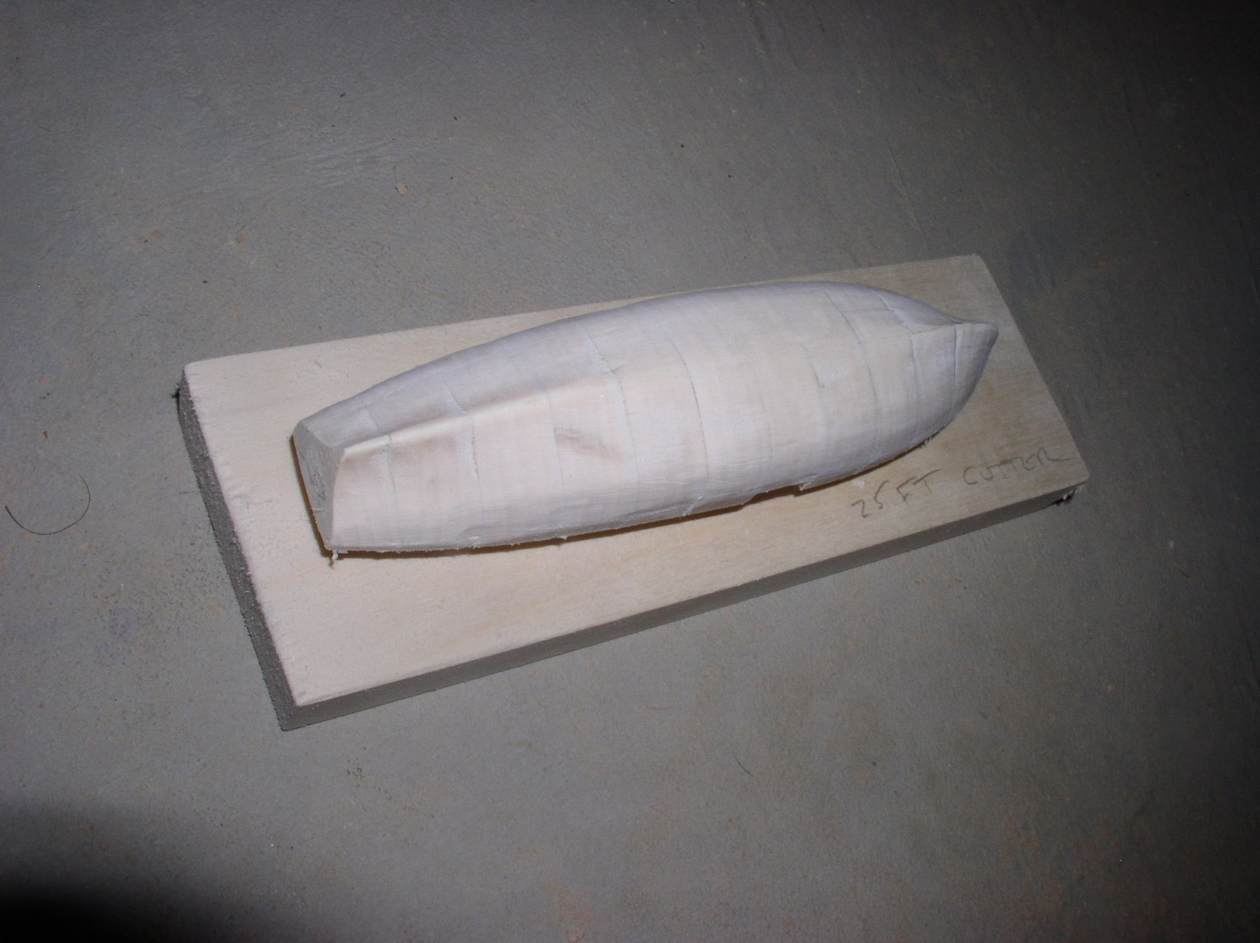
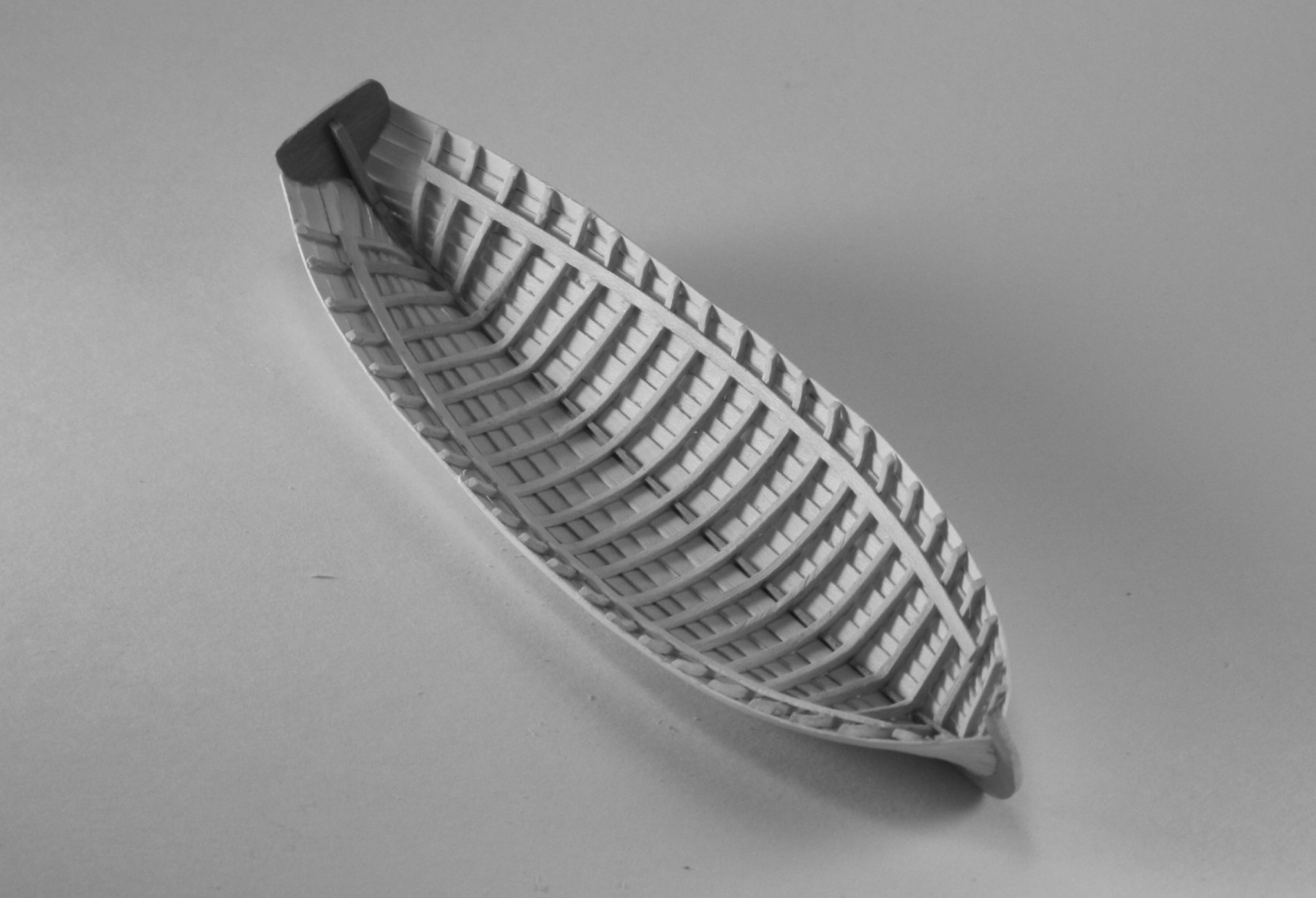
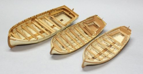
Go for the balsa if it works. My own experience has proven that holly is fantastic for the tiny frames used in the ship's boats as well as the planking. First they are easy to cut to shape with the floor area having a moulded dimension that is more than the higher portion of each frame and when soaked in water for a few minutes, they can be bent quite easily around a carved plug that is the shape of the boat. Pure white holly is getting harder to come by but the off white wood should be easy enough to find and it does not take much wood to have enough for a fleet of ships' boats frames.

-
I like Danny's idea best1 I have shipped as far as US to Europe on several occasions but the recipient always paid for the crating which was done by professionals. Even then be careful that they know what they are doing. The first time I did this the fellows that came to pick up the model asked if they could take off the masts!!!! I was not home, but the admiral told them to leave and called me. I called the freight forwarder and the next crew knew what they were doing. I did see this particular model some months later on display in a beautiful custom case and it was in perfect shape. Allan
-
Simple Framing Question
allanyed replied to t5956ws's topic in Building, Framing, Planking and plating a ships hull and deck
Lacking any other contemporary information, the sided and moulded (in and out) dimensions of the floors and futtocks can be found in the scantlings of the 1719 and 174 Establishments, the Shipbuilders Repository of 1788 and Steel's Elements and Practices book of 1805. You can find some of these in Goodwin and a few other books or all of them in Scantlings of Royal Navy Ships. None of these may apply to your ship, but will at least give an idea on how the moulded and sided dimensions reduced as they rise. Allan -
Scale of Gratings
allanyed replied to Ferit's topic in Building, Framing, Planking and plating a ships hull and deck
Ferit, Perhaps the below will help you. This is from a British ship of 1803. The dimensions are for a 1/4" = 1 foot scale model. Looking at the coaming in your photo, if it the kit is accurate, this appears to be from much earlier as the coaming is quite shallow compared to later years. Allan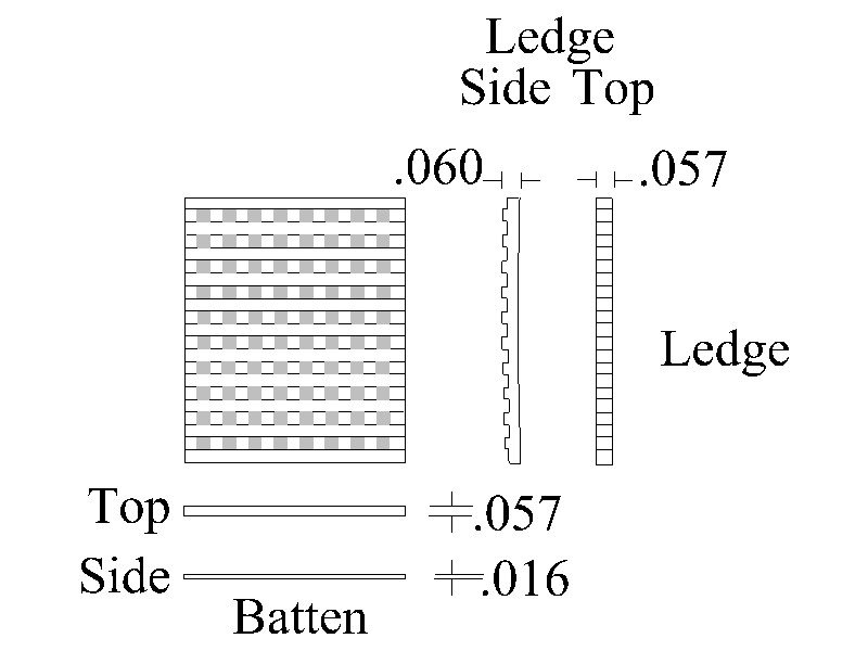
- 8 replies
-
- 6
-
-
- measurement
- scale
- (and 1 more)
-
Further to Frankie's comments, rule of thumb that I learned back in my boating days was that the amount of anchor rode (chain and/or line) let out should be about 5 to 7 times the depth, so if there is even only 20 feet of water, that is at least 100 feet of rode let out. A lot depends on the type of bottom, wind and speed of the tide. Question, would the Bluenose and other similar schooners have used a rode of all chain or combination of rope and chain? Allan
-
This may not be of any help to you at this point, but on the "old" ships the decks were holystoned which gave them a whiter versus grey finish. Holly is an excellent wood to give this look. Allan
-
Knighthead
allanyed replied to brobertson's topic in Building, Framing, Planking and plating a ships hull and deck
Welcome to the fray Bruce! Allan -
Knighthead
allanyed replied to brobertson's topic in Building, Framing, Planking and plating a ships hull and deck
Hi If you would be so kind, please let us know a little more. What is your name? What ship? Is it a kit, POF, or POB? Different solutions depending on the type of build. You will surely get some responses, but need to share a little more information. Thanks and welcome to MSW Allan -
Gluing Planks When Wet
allanyed replied to mikiek's topic in Building, Framing, Planking and plating a ships hull and deck
I strongly urge you to read the tutorials here on planking. If the strakes are properly cut (straight strips are not good for much of the planking) and pre-bent while wet then left to dry, there should be no edge setting issues. Walnut is a beautiful wood, but not for ship model planking, IMHO, other than perhaps for the wales to give the dark contrast rather than painting. If you can, use a more appropriate wood such as Costello box, pear or some such. If you follow the tutorials, clamping is not needed for the most part. Where clamps are required, Ed Tosti has provide a lot of information on clamps in his threads and in the Naiad books. Just one opinion based on my own experience over the years. Allan -
Cathead Angles
allanyed replied to allanyed's topic in Building, Framing, Planking and plating a ships hull and deck
Thanks everyone for your input. I will chock it up to experimental on paper, if not in practice. Even if in practice, and an assumption that it did not work well, it would likely have been redone in the more commonly known fashion. At least that is my story and I will stick to it until proven otherwise. Thanks again! Allan -
Cathead Angles
allanyed replied to allanyed's topic in Building, Framing, Planking and plating a ships hull and deck
Thanks Brian and Mark. Your answers are among the several I have considered. But, before I change a contemporary drawing, I would love to find some other examples or something definitive. Another interesting thing on this drawing is the body plan(s) which show both port and starboard for the forward stations and port and starboard for the aft stations. This was a first for me as well as the cathead. Allan -
I have come across something that I have not seen before. The cathead on the profile drawing of Antelope 1703 shows the cathead angled up and aft, not up and forward as seen on other plans and contemporary models. In looking at photos of models and plans of late 17th and early 18th century British ships, none that I have seen show the cathead angled aft. Has anyone seen this configuration before? Thanks Allan
-
Larry, You mention in a previous post using boxwood. Seems the wood in the photo is a bit grainy for boxwood. Did you try English boxwood or is it Costello? English box is a bit on the yellow side colorwise but will hold the tiniest detail without breakage compared to other woods. It is hard to come by so I use what little I have in the bin for carvings only, and Costello boxwood for most other parts whenever possible. Allan
-
Deck Plank Size
allanyed replied to rlundy90's topic in Building, Framing, Planking and plating a ships hull and deck
My pleasure Ron. Just keep in mind those are dimensions for 17th century and Norske Love is 18th century so these dimensions may not be correct. Cheers -
Beam Arms
allanyed replied to allanyed's topic in Building, Framing, Planking and plating a ships hull and deck
Mark, It is the Hampton Court, 1709 Allan -
Deck Plank Size
allanyed replied to rlundy90's topic in Building, Framing, Planking and plating a ships hull and deck
Ron I looked for a Norske Love to get a better idea on the year, but cannot find a Norske love from the 17th Century. I found two from the 18th century including the Norske Love 1765 kit by Billings. If this is your model, any information from 17th century ships I gave may be inappropriate for such an 18th century ship. The information I have is for a British ship not a Scandinavian ship so may be off anyway. Regardless, here goes if anyone is interested in an English ship from the late 17th century...... I cannot find if the following are based on contempary drawings, scantlings, documents or the wreck, but looking at the deck plans for Lenox in The Restoration Warship, the planks for the gundeck are 14" wide at midships. The upper deck about 11.5" at midships. The lengths vary but are about 30 feet long. The shift shown is a 3 butt pattern for the most part. The Orlop deck planks do not shift as they are laid on the recess cut into the top edges of the beams and all appear to be about 12" wide. Quarter deck and poop deck planks appear to be 9" wide at their respective forward ends and taper to about 6" at the aft end. The taper will depend on the athwartships dimension differences at each end. The forecastle planks are 9" wide at their aft end and taper appropriately. There is no joggling of planks on these three decks. There is no appearance of anchor stock planking on the outboard planks of the gun decks as found in later periods. The Norske Love could very well have had anchor stock planking on the outboard 3 or 4 strakes. Allan -
Deck Plank Size
allanyed replied to rlundy90's topic in Building, Framing, Planking and plating a ships hull and deck
For the late 17th century, there is a wealth of detailed information in Richard Endsor's book The Restoration Warship. There are drawings, a scantling list from the 30 ship program, and more. He did a huge amount of research and the amount of information is immense. For more details on the deck planks, what size ship and which deck are you looking for? For the gun deck as an example, a seventy from the 30 ships program had waterways 6.5" thick, 14.5" in breadth. The rest of the gundeck plank to the hatchway was 4" thick. Between bitts and main partners, 3" thick. Hatchway plank was 2" thick. There were two spikes in each beam and 2 treenails in each ledge. The upper deck planking was reduced in thickness as were the decks above. Hope this helps a little. Allan -
Beam Arms
allanyed replied to allanyed's topic in Building, Framing, Planking and plating a ships hull and deck
Henry, it is hard to describe in words. They are best understood when seeing them in a drawing. Hope it is clear enough for you to see the arms on the drawing. Allan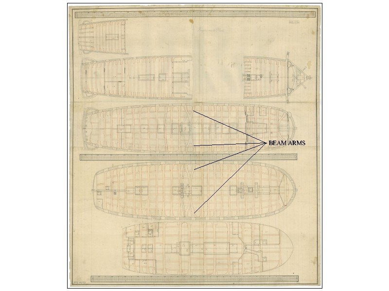
-
When did the use of beam arms begin? The earliest drawing showing them that I could find is a detailed set of deck plans for Elizabeth 1706. Drawings of the Lenox in the Restoration Warship which was from the late 17th century show no beam arms. Goodwin's Sailing Man of War does not give any indication of when their use began. Specific vessel that I have in mind is Antelope (50), 1703. The only drawings of Antelope that I can find do not help. Thanks, Allan
-
Still enjoying these a lot! The water in the painting of HMS Faulknor reminds of Carl Evers' work. Thanks again for sharing. Allan
-
Thanks for sharing, these are fabulous. Allan
-
Thanks Mark, I will take a look at the contemporary models in Museums section but I really appreciate your offer. Will let you know Allan