


allanyed
-
Posts
8,149 -
Joined
-
Last visited
Content Type
Profiles
Forums
Gallery
Events
Everything posted by allanyed
-
 Mike, I did some digging and cannot find any single addition, only the two volume set, but they can be purchased separately Most of the models I see on the forum would make Volume II the most useful, but I have been digging into a ship that would require me to have Volume I if I cannot find the information elsewhere in my small library. I really hate having to see the admiral rolling her eyes if I mention the need to buy another book related to ship modeling. She does not buy into the argument that I keep using that it is an investment Allan
 -
Advice for planking
allanyed replied to Slowhand's topic in Building, Framing, Planking and plating a ships hull and deck
What's your name? I hate to be rude and have to address you as a blank space. Regarding your concerns about not having tools to spile -----. An Xacto or scalpel, maybe a $10 coping saw, a pencil and some card stock and paper is about all you need. What tools do you feel you are missing? Allan -
Nice buck mount on the wall!!! Allan
-
Mike Because a 24 pounder could travel that far does necessarily mean it was allowed to. If it recoiled 17 feet those opposite a hatch would wimd up down on the next deck. Look at the sketch I posted earlier. That shows 15 feet of travel on a deck that carried 24 pounders. These cannon never come inboard enough to use the tools without going through the gun ports. Allan
-
What would be achieved by doing this? Models that are over 200 years old are found all over the world and seem to be in good shape if cased in air. Light and "critters" are more of a problem, me thinks Allan
-
Dafi I don't know about copyrights in Europe but in the US it is for the life of the author plus 70 years if published after 1978. If prior to 1978 it is 95 years. It was published about 1995 so still protected and I assume not available for free. I have volume two and it was worth saving up for. Allan
-
Hi Ed Did you make the lap, then pre-assemble, then drill the holes so they are perfectly aligned. I see the cut in the top of both the rim and the cross trees. May I assume the rim is upside down for the photo? Thanks once more for sharing. Gorgeous stuff! Allan
- 3,618 replies
-
- 3
-

-
- young america
- clipper
- (and 1 more)
-
Mike, I think Russ means the bore length, not the bore The handles of the tools had to be long enough to reach into the entire length of the bore plus have enough length for a sailor to hold with two hands. With the gun run all the way in, there was not enough room to get the tool into the barrel unless it was taken outside the hull, presumably through the gun port. The sketch describes it better than I can put in words. The gun has a 9 foot barrel and the beam is 40 feet on a 70 gun ship of 1706. The handle of a tool is shown extending outboard of the hull. Allan
-
Bending with steam easily
allanyed replied to a topic in Building, Framing, Planking and plating a ships hull and deck
I prefer dry bending by far, but sometimes soaking is a better way to go. If that is the case, for me, steam and hot water is way too much work and too much wasted electricity. It provides no advantage over using cold water. I use various lengths of PVC pipe with one end capped. I put in a few shaped pieces of wood n the tube and fill with distilled water. I don't trust the chemicals in the tap water. Tap water may not eat the lining of my stomach, but may have an adverse effect on the wood color or some such. I do have my priorities! Depending on the wood and thickness, it takes from a few minutes (holly) to an hour or so (pear and castello). I usually put in a few pieces at the end of the day and they are ready by morning regardless of the type of wood. I notice that most bob up as they float in the water in the pipe, so I will put an end cap on to hold them down. When they are ready, they don't pop back up once the end cap is removed (and they often sink to the bottom.) Once the pieces are all out and used, the water goes back in the jug for the next round. Allan -
ancre Le Fleuron by juzek - 1:27
allanyed replied to juzek's topic in - Build logs for subjects built 1501 - 1750
Hi Juzek, The sketch will be a better description. The angle of the rabbet continually changes so I was wondering how you will accomplish this change. Thanks Allan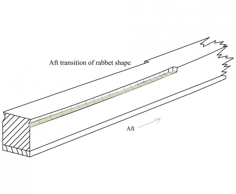
-
To answer the question, yes I enjoy rigging. As I mostly work on British vessels, I live by Lees Masting and Rigging for the details on everything from dimensional information to some fine drawings on blocks and other pieces. For schooners, my second love, Chapelle's American Schooners book gives a lot of details on rigging these vessels. David Antscherl's Volume IV of TFFM offers a lot of great information on rigging. Peterson's Rigging Period Ship Model offers a lot of good information on rigging a late 18th century frigate. With these there is no reason to fear masting and rigging due to putting the wrong line in the wrong place, or using the wrong size or belaying points, some or all of which may be reasons why so many don't like rigging. Allan
-
Chris Never heard of a site with free patterns on figure heads but pages 243- 254 Volume II of David Antscherl's The Fully Framed Model is an excellent tutorial on drawing your own. You can find dozens of photos of figure heads on line, then use those as a sample from which to prepare your drawings. Once you finish your drawing you can make a clay sample before carving the wooden one. The clay is easy to work, fix, and do what is needed to make it right. This then gives you a three dimensional model from which to work Allan
- 1 reply
-
- 3
-
-
Hide wood
allanyed replied to Don Quixote's topic in Building, Framing, Planking and plating a ships hull and deck
Regarding how well hide glue works, I have hide glue residue on my work bench which has been there since about the 1920's. It ain't coming off unless I chisel it and I have no plans to do so. This bench belonged to my grandfather who was a life long cabinet maker and the bench has stayed in the family. He used hide glue for many many years. But, he switched to carpenters glue, unless he was doing restorations of antiques that originally were built with hide glue. He taught me a lot and swore that the carpenters glue was as good or better and soooooo much easier. Allan -
ancre Le Fleuron by juzek - 1:27
allanyed replied to juzek's topic in - Build logs for subjects built 1501 - 1750
Juzek As the angle at which the garboard strake meets the rabbet is dynamic, will you adjust the angle of the initial cut of rabbet with chisels as you show in the photos of the rabbet at the stem or will you use some other method to finish the rabbet? Allan -
ancre Le Fleuron by juzek - 1:27
allanyed replied to juzek's topic in - Build logs for subjects built 1501 - 1750
Juzek, Thank you for your posts. I am envious of that stack of planks of pear! Looks like you cut down a tree (or two or more) and have a nice supply to last a long time. I like the color of this unsteamed pear very much. Allan -
Mike, Thanks for sharing the photos. VERY nice finish on all fronts as your attention to the little details is paying off. Allan
- 452 replies
-
- 4
-
-
- cheerful
- Syren Ship Model Company
- (and 1 more)
-
Great idea John. I hope you don't mind a question. Is your model a kit? The reason I ask is that the ratlines appear to be rather heavy compared to the shrouds. Mondfeld and others calls them out at about 1.5" circumference or just under 1/2" diameter. Surely these varied from era to era and nation to nation, but probably not much. This may seem small but the linear breaking strength of 3 and 4 strand 1/2" diameter hemp rope is over 2000 pounds. Regardless, thank you for sharing your idea! The clove hitches are a treat to see. Allan
-
I don't think there are any wooden off the shelf carriages. If the model is the Victory itself you will need a number of different sizes so I agree with Pat's post that you are far better off making them yourself. Allan
-
Great work as we have come to expect Ed. I love the unplanked method, including the ship's boat, and I am sure everyone here understands and appreciates it. I just hope not too many lay people that do not know this hobby ask you when you are going to finish the model, or worse, ask if the planks fell off Allan
- 3,618 replies
-
- 4
-
-
- young america
- clipper
- (and 1 more)
-
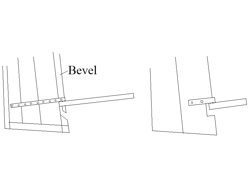
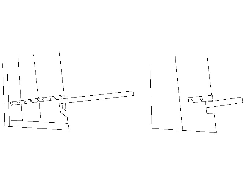
Thanks Druxey The bevel (and later, rounding) on the forward face of the rudder is an important feature and appears to go unmentioned in kits. I have edited the sketch and added the line indicating the bevel. I also adjusted where the hinges actually are installed on the model. My fault for rushing the first sketch. Allan
-
Poor results with carpenters glue
allanyed replied to a topic in Modeling tools and Workshop Equipment
To address your problem, I really would like to be able to address you by some name, even if you make one up. What do we call you? Aliphatic (carpenter's) glue is by far the most useful for wood to wood based on many many responses here at MSW and in my own experience. I assume you had a clean surface on each piece. Gaging clamping pressure? I try to use clamping or weights that would be the equivalent to modestly hard finger pressure. Too little, too much, not good. If you are having to really force things together with clamps or a lot of weight, the fit is bad, not the glue. Just one opinion. Allan -
Thomas, I think by prototype, Wefalck means the way it was done in the shipyard back in the day. The attached sketch shows a hinge and rudder on the left that is close to what was commonly used on the actual ships (based on a drawing from Goodwin's Sailing Man of War) versus the design from your kit on the right I could not see all the details from your photo so I may be off a bit on the sketch and I apologize for that. Allan
-
Greg/Druxey I might have missed this in an earlier post, but is the material for the flag silk span? Also, what is the material used for the cover? Thanks Allan
- 9 replies
-
- 4
-
-
- greenwich hospital barge
- royal barge
- (and 2 more)
-
Chuck While the model as a whole is wonderful, I especially enjoy seeing your attention to detail. For example the eyes in the channels are not standing too proud as seen on many other models, but rather are set more deeply as they should be. Very well done! Allan
- 1,051 replies
-
- 6
-
-
- cheerful
- Syren Ship Model Company
- (and 1 more)
-
Charley First, thank you for sharing. The planking style you posted is a first for me as I had never noticed this kind of layout before now. What I have always seen are the ends of the planks always end at the rabbet at going up the stem, not hook scarfed at the sheer strakes. Look at Chuck Passaro's Cutter Cheerful drawings and model and you will see what I mean. I may be wrong but I don't think that planking is close to being correct. I realize the drawing you posted shows this, but is the drawing correct? I am more than open to be corrected myself, but in reality I think it would be a very weak hull structure. I am always ready to live and learn and this one has me fascinated. Allan
- 362 replies
-
- 4
-
-
- active
- revenue cutter
- (and 1 more)
