HOLIDAY DONATION DRIVE - SUPPORT MSW - DO YOUR PART TO KEEP THIS GREAT FORUM GOING!
×


allanyed
-
Posts
8,149 -
Joined
-
Last visited
Content Type
Profiles
Forums
Gallery
Events
Everything posted by allanyed
-
 Fam, If the drawings show the ship as horizontal, which I assume they are, the vertical height of the hawse hole is also the diameter assuming the hawse holes are round. Keep in mind Druxey's point about the angle at which you open up the holes. Allan
 -
Jim, A complete description of properly rigging and securing the bower and kedge anchors can be found in pages 137 -143 in Volume IV of The Fully Framed Model by David Antscherl. Additional good descriptions can be found in Lavery's Arming and Fitting on page 53-54 as well as Darcey Lever's The Young Sea Officer's Sheet Anchor and James Lees The Masting and Rigging of English Ships of War . There is more than just having a line that goes through the cat sheaves to a block and hook. Once the anchor is raised, it has to be brought up to the hull and secured. Fish davits come into play for this chore. Keep in mind that after 1773, the fish davits were shortened and secured to the fore channels with a shoe. Many plans do not show these very clearly, if at all. Allan
-
I used to be a member of the New Jersey Ship Modeling club, but I do not remember the name of the member that showed this. You may want to PM Chuck Passaro as he is an active member of the club and may have a recollection, or if not, he can ask the membership. I believe their monthly meeting is tomorrow night. It has been some years since I saw the technique so only the older members may remember. Good luck Allan
-
Philippe Your solution proves the old saying has validity, where there is a will, there is a way! Great idea that you had. I have seen some fantastic plastic scratch build models wherein (as I remember his explaining how he did it) the hull was shaped with pine or some such, then some type of opaque sheet plastic (may have been polystyrene) from the local hobby store was heat shrinked around the wooden plug. He did the same for many of the upper works from what I recall and they looked remarkable. Also knocked off a lot of weight when the wooden plugs are removed. Allan
-
Ed, Collectively we ran out of adjectives a long time ago, so suffice it to say, I love watching each and every post. Allan
- 3,618 replies
-
- 5
-

-
- young america
- clipper
- (and 1 more)
-
Well done once again Danny. I see myself referring to your log down the road as you have provided quite a few detailed "how-to" instructions including the netting technique. Allan
-
Keith, They look so good as wood, sorry to seem them leafed! Allan
-
Bluenose Is the Snowberry a Flower Class corvette from WW II? If so, I assume there is more standing rigging and it is wire, not hemp or other. Check with Chuck at Syren as suggested, but I am not sure he offers wire rope. Allan
-
Hi Tom, Good call. You are absolutely correct, I mistakenly pigeon holed myself, thinking only of older wooden vessels. If I ever found the fortitude and gained the necessary skills to build a steel vessel I am sure I would use a few liters of silicone and resin. Keith, I suspect casting parts for the overhangs on the side lights would have been a reasonably good way to go, but wood, assuming they will not be painted, as you have shown, sure looks nice. Thanks for sharing the pics. Allan
-
Keith, I am a big fan of making molds and parts from these molds so I do not want to discourage you in any way. But, are all ten piece exactly the same? Other than cannon, there are few things on a ship that are exact duplicates of another part. Length, angle, siding, &c. change from piece to piece. What trim parts are these? Can you send a picture of the master? In any case, any silicone RTV found in hobby shops, Micro Mark or other such suppliers will work. You will also need mold release, casting resins and solvents to clean the mold release from the parts, and uncoated disposable cups. By the time you are done you will have at least $40 or $50 invested and spend more time than if you made them all of wood. If you do go ahead and make the molds, it will be good experience, and hopefully an enjoyable one for you. Allan
-
Keith The only painting that I have seen that MAY show the frieze work accurately is the John Clevely painting at NMM. To get a clear digital copy you would have to pay for a copy of the painting unless you can find it elsewhere. My experience with their digital copies is five out of five stars and may be the only way to go. Then again, the painting may not be as detailed as you need, nor accurate. To produce a top quality frieze, Volume II of The Fully Framed Model gives a detailed description on producing your own frieze paintings. Allan
-
Doc, Truly a wonderful piece. I especially like your use of different woods. Allan
-
Remco, I just checked in for the first time in a long time as your build came up when I was searching for brick hearth information. I have now spent some hours following your build to catch up since mid 2014. Remarkable workmanship! Thanks for sharing so many clever ideas. Allan
- 1,214 replies
-
- 1
-
-
- sloop
- kingfisher
- (and 1 more)
-
The above answers your question but I must comment on the drawing you posted. You are right, the quality is a bit off. How can the ends of the line wrapped around the drum both drop from the same side of the drum? Reminds me of some far out designs in Mad Magazine back in the day like the 2/3 tined fork in the attached picture. Allan

-
I agree with the above. Rotary tools have their place, but this probably is not the place. You can shave a thousand of an inch with a chisel. I defy anyone to do that with any consistency with a rotary drum. Allan
-
I agree they were probably more permanent than not in actual practice, but I why then use a cap square to hold them down onto the false rail rather than a more simple, permanent, means of fixing them in place? Allan
-
A TOAST TO YOUR CONTINUED BEAUTIFUL WORKMANSHIP. TRULY IMPRESSIVE. Your method of making shroud cleats so they are all the same size and shape is very useful, thanks for sharing that. Allan
-
I bought this book as a reference to my current project, but have to say, it is a delight to read from many views. It is based on the Lenox (70 gun) which was the first of the 30 ship building program of 1677. Anyone interested in the construction of ships from the late 17th century into the 18th century would be extremely happy to have this book as a reference and for a very interesting read in general. Richard Endsor has provided a great deal of history, his own drawings and paintings, many drawings by Willem Van de Veld the Elder and others, photos and more. Richard was educated as an engineer and his attention to detail inherent with most engineers shows through, but his talent as an artist is something not to be missed. I can go on and on but suffice it to say that I am extremely pleased to have this in my library. Allan
-
Hi Ed, Magnificent work as always. I was overjoyed to see you using spring clamps. I thought that was my own dirty little secret that would be too embarrassing to share. They have their place in my opinion, but I have had more pinch injuries with these over the years than the occasional cut from an Xacto blade. As always, safe and slow is the way to go. Enough with the books already. Between you, Antscherl, Endsor, my Christmas list is always taken up before I can think of other things that would be fun to get. Allan
-
Unless my math is off, a nine foot cannon will only be 1/4" long +/-. I am curious as to what ship you are building and if it is a kit. thanks Allan
-
surname of Nelson's Captain at Trafalgar
allanyed replied to cnemo's topic in Nautical/Naval History
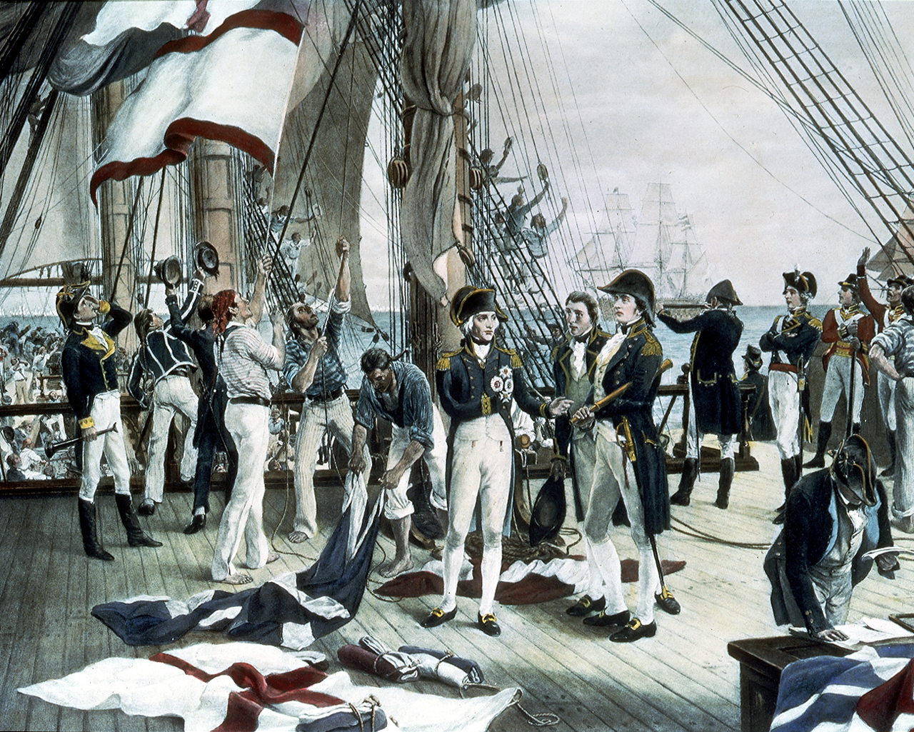
The following painting shows both Nelson and Hardy as well as Blackwood. The painting and following explanation are from the NMM collections. PAH8019 A photogravure after the painting, ‘Nelson’s Last Signal at Trafalgar’, by Thomas Davidson. Nelson is shown in the centre of the image standing on the deck of the ‘Victory’. He gestures towards the ship’s captain, Thomas Hardy, with Captain Blackwood of the ‘Euryalus’ looking on.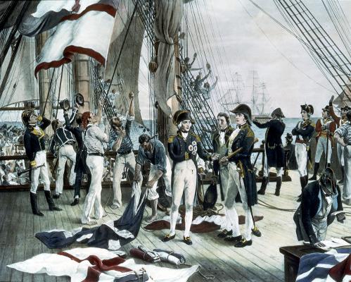
-
The black stripe
allanyed replied to SaturnV's topic in Building, Framing, Planking and plating a ships hull and deck
Marty, Pages 57 and 58 in Goodwin's Arming and Fitting give a lot of information on paying the hulls, The description he gives is of tallow, rosin, sulfur, oil from whales and seals, and pitch, no mention of lead at that point. The black stuff was half the price of white stuff and became predominant over white stuff by 1702, but mostly on ships in home waters. The white stuff was thought to be superior and was used for the supposedly more demanding waters of the Caribbean and Mediterranean Seas. When brown stuff came into use later in the eightheenth century, it was used from keel to about 3 feet below the LWL. The next three feet were payed with tallow and lime and had a skirting of white lead and tallow. Allan -
I really like the breeching line laying on the deck. Good thing they used a light load or that piece would have rolled until it hit something solid enough to stop it, hopefully. Allan
-
The black stripe
allanyed replied to SaturnV's topic in Building, Framing, Planking and plating a ships hull and deck
As far as liking the looks of the paint going to the water line, I see no fault from the liking it or even when considering the historic aspects. No doubt each yard's building methods varied from the others in many ways. In fact, I love the look of the models I have seen that were built by David Antscherl who sometimes planks the bottom from the keel up to the underside of the wales with holly to replicate the "white stuff" used on the ships' bottoms before coppering came into use. This can be seen on his models of the Resolution and Comet. In actual practive I believe the white stuff was usually applied to the water line, but the look of planking with holly to the wales looks great. Allan -
Juergen, I like the fix a lot. Great job! And no one but those of us that saw your photos will ever know! Allan