allanyed
-
Posts
8,149 -
Joined
-
Last visited
Content Type
Profiles
Forums
Gallery
Events
Everything posted by allanyed
-

HMS Alert 1777 by Jaekon Lee - 1/64
allanyed replied to Jaekon Lee's topic in - Build logs for subjects built 1751 - 1800
Hi Lee, Your workmanship is obviously terrific, but I have a question. Assuming there are no gun ports, the sides of which the frames would form, why are there filler pieces, offsets, and dog legs in some of the futtocks? I understand the siding of each futtock reduces as you go up, so there would be a step at the butts, but I cannot figure out a reason for the other shifts of the futtocks. Again, your workmanship is very good, but I would like to understand the whys of the dispostion of the frames. Thank you Allan -
Richard, From a practical standpoint (cost and availablity) I choose to use Castello ( Costello) for the bulk of the pieces that go into a model for the many good reasons given in a number of previous posts and topics. I do prefer European boxwood for carvings. Even small (2" diameter) logs can be used and two or three short pieces can last for years. The yellow will darken over time as will most of the woods used in our models. Allan
-
Danny Your rigging looks so good it has pretty much convinced me to rig my next model when I get to that point. As it will no doubt be a couple years down the road, I do have a chance to change my mind Allan
-
All the good compliments have been taken, drat!!!! I do enjoy checking in on your progress Ed as I need a good humbling experience every so often and your workmanship does satisfy that need. Great stuff! Allan
-
Hatch coamings.
allanyed replied to Mundie's topic in Building, Framing, Planking and plating a ships hull and deck
Hello Mundie Are you talking about the hatch coamings and head ledges or the deck beams and carlings on which the coamings and ledges rest? Allan -
Clipper Try the collections section of the National Maritime Museum. There are a lot of plans of launches, barges, and other ship's boats. Lavery's Arming and fitting has a lot of details on ship's boats and of course W.E. May's book Boats of Men of War is a wealth of knowledge. Scantlings can be found in May's book as well as Scantlings of the Royal Navy. Allan
-
Bud If you can tell us the name and size of the ship as well as the year, the sidings of the floors and futtocks as well as room and space can be determined. From these you can determine the number of frames. Are the stations shown on your drawings? I am doing a framing disposition drawing of the Litchfield (50) 1730, built to the 1719 Establishment now, so can share the issues in having the frames form the sides of the ports etc. Do any of your existing drawings show the gun port locations? Allan
-
Medic, Actually I do prefer paper when in the workshop, so try to have the appropriate books and plans within reach of the work bench. Allan
-
Medic There used to be and maybe there still are one or two. I have not seen any in many years that actually help building models the way this site does. Even those that were out there cannot compare to the information you get at this site. You will get more new information from this site in a day than you will find a year's worth of magazine articles. The building logs alone give more tips on how to than a magazine. AND, if you do not understand a particular item, you can ask and get answers very quickly. Allan
-
I have used the same barber shears for years. The best go for $500 to over $1000, but are meant for thousands of snips per week. I found a pair with convex edges for $80 that will last a couple lifetimes of rigging without having to be sharpened. These were $200 shears that I bought at a cosmetics and hair trade show in the last hour of the last day. I can CUT, not tear even the tiniest strand right at the knot without having to have any tension on the piece being cut. In the end, quality comes with a price as is usual. Allan
-
I really enjoy watching your build continue to grow. Your work is great to see, but I do agree with Isalbert as the muntins are normally smaller than the sashes and stiles. Allan
-
Jim, Can you tell us the ship and cannon size in the contemporary illustration? I doubt that the Rattlesnake would have had cannon large enough to use double blocks in the tackle, so Brian, be aware. That is a great drawing BTW, thanks for sharing. Allan
-
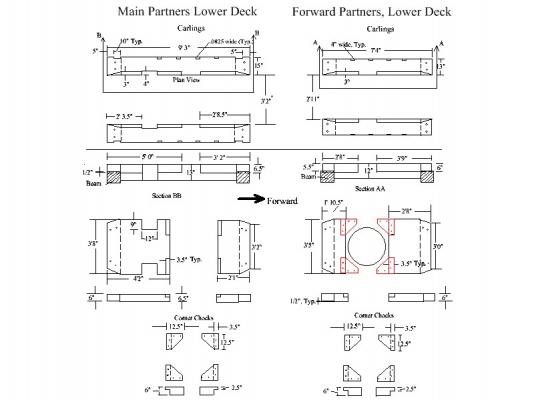
Peter Goodwin gives a rather detailed explanation and provides sketches of the use of the wedges in his Construction and Fitting of the English Man of War on pages 169 and 171. The opening area inside the partners is about 10" to 12" larger than the diameter of the mast thus the wedges are about 5 or 6 inches thick where they contact the mast and partners. The corner chocks are dressed to the appropriate diameter, but he does not say or show the carlings or cross partners being dressed to form a circle. He does say that many of the wedges had to be made "tailor made". Allan
- 17 replies
-
- 1
-

-
- pof swan series
- tffm
- (and 2 more)
-
While the dimensions are not necessarily correct for your ship, this may give a better understanding of the marriage of the partners and surrounding beams and carlings. Allan
- 17 replies
-
- 7
-
-
- pof swan series
- tffm
- (and 2 more)
-
Hi Russel, I see that was your first post, so welcome. Which ship? If you go to the NMM site, you may find a little information there. http://collections.rmg.co.uk/collections/objects/66179.html , fourth photo, shows a castan on a 50 gunship from 1703. Obviously sizes cannot be taken, but what I found a little different is that the top is not round, but rather a decagon with 10 square openings for the bars. The above concerning Lavery and the 1719 Establishment is great advice but as I have found is very often the case, there is conflicting information. The scantlings in the 1719 Establishment calls for 12 bars, not ten. 1703 is obviously closer to your 1706 vessel than the 1719 Scantlings thus may be more accurate. Choose your own poison. I doubt anyone will fault you on whatever you choose. Allan
-
Ed, Your camera work has been great in helping us see the details in the build. This has been a fun ride watching her take shape but I do not look forward to seeing all that beautiful framing get planked over. Allan
- 3,618 replies
-
- 3
-
-
- young america
- clipper
- (and 1 more)
-
Treenails
allanyed replied to wallyh's topic in Planking Techniques's Click Here for Topics dedicated to planking!!!!
Dave, YOURS IS A BETTER WAY Allan -
Treenails
allanyed replied to wallyh's topic in Planking Techniques's Click Here for Topics dedicated to planking!!!!
I've used, tape, black, blue, and red marker to mark the depth on the drill bit to avoid going too deep and passing through the deck beams and frames. Allan -
Treenails
allanyed replied to wallyh's topic in Planking Techniques's Click Here for Topics dedicated to planking!!!!
BRIAN C What is the smallest diameter you achieve with silver ash? I normally pull down to smallest hole on the Byrne's draw plate with bamboo but have never found another material that can be worked that small. Allan -
Ed, Every deck beam is the same length and then cut in length to fit. Is there a reason you do it this way rather than making each closer to the needed length then field fit? Regardless of why, the whole thing is just great! Allan
-
HMS Leopard by gobi71 - 1/300 scale
allanyed replied to gobi71's topic in - Build logs for subjects built 1751 - 1800
Gobi71 Thanks for posting your photos. I have always been a fan of micro scale models, but have not had the fortitude to actually try. I look forward to following your build, but would really like to hear about what techniques and tools you use as you post your photos. Maybe you can teach those of us that would like to try these small scales enough for us to take a chance. If you would be so kind, please let us know your name so we can address you properly rather than Gobi71, Thanks again Allan -
Larry, Look at the framing disposition drawing of the Alfred at the NMM collections site. http://collections.rmg.co.uk/collections/objects/80355.html It is not the clearest resolution, but far forward it is evident the floors are on the forward side of the paired frames and on the aft side moving aft of the deadflat. You can enlarge it, save and download, and enlarge even more, but it does get fuzzy. Look at Gary Bishops Alfred build. I am not sure you can see this in his earliest photos, but I imagine he would be happy to answer your questions if you post or PM him. His framing is based on the actual framing disposition but is a wealth of information for anyone building the Alfred. Allan
-
Danny, The served collars are superb. Your workmanship and attention to detail was evident at the beginning of the build. As good as it was, I think you have gotten even better! Allan
-
Endeavour Longboat
allanyed replied to Rick01's topic in Building, Framing, Planking and plating a ships hull and deck
Rick, That is why many builders like to scratch build. The biggest problem with scratch building though is that there is no one to blame for mistakes! Allan -
Endeavour Longboat
allanyed replied to Rick01's topic in Building, Framing, Planking and plating a ships hull and deck
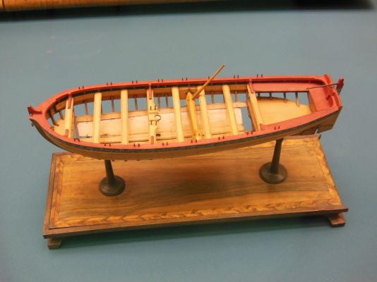
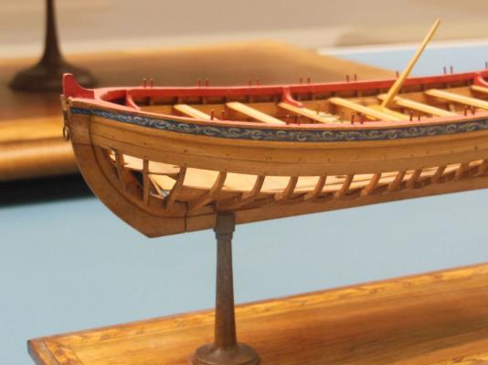
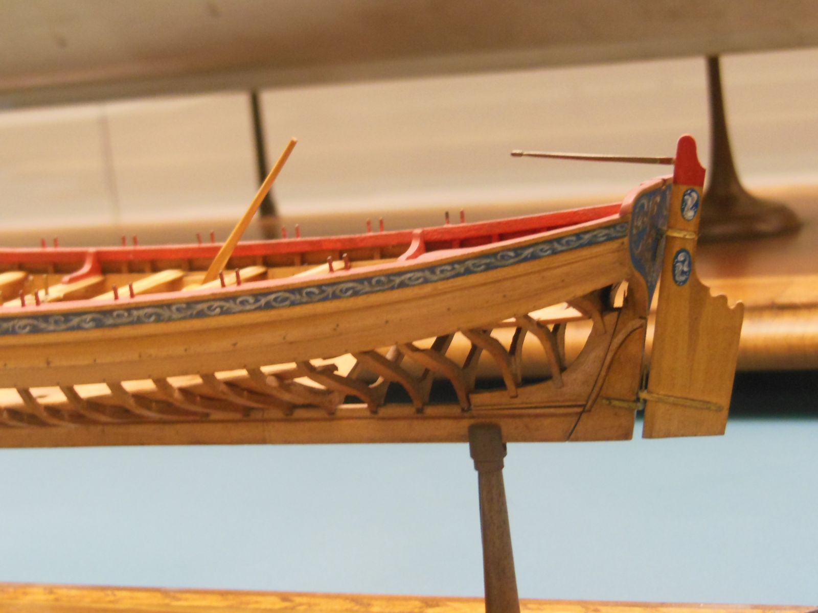
Attached are some photos of a long boat model from NMM that may be of help. Based on the locations of the tholes, it is probably a double banked boat. You may want to take a look at 18th century long boat build forum here at MSW for lots more details Allan