


allanyed
-
Posts
8,111 -
Joined
-
Last visited
Content Type
Profiles
Forums
Gallery
Events
Posts posted by allanyed
-
-
9 hours ago, CiscoH said:
i would have done it by eye and gotten a rounded uneven rabbit.
As Dave points out in his post #6 part of the difficulty in making the rabbet is that the angle is dynamic and is not at 45 degrees or any specific angle the entire length. Some folks have found that a SHARP chisel can be a far easier tool to use to get the angle required to match that of the frames/bulkheads.
Allan
- Cathead, robert952, ferretmary1 and 1 other
-
 4
4
-
Welcome aboard Miguel Your project looks to be very interesting and hopefully a lot of fun. I am sure you will get all the support you need (maybe too
much😀) When I say too much, for example, when it is time for the cannon, please feel free to PM me as I have detailed drawings of three patterns of Spanish cannon covering circa 1715-1756, 1756-1765, and 1765-1805 that I can send to you if you want them and compare with your plans.
Allan
-
13 hours ago, aliluke said:
I used the excellent Vanguard Models kit for my boat but they'd be the wrong scale for Victory.
The Vanguard boats really are good, but alas, the scale is wrong for your 1:72 build as Alistair states. It is not very difficult to make your own boats and they will look realistic. There are a lot of contemporary plans and all the scantlings needed readily available if you want to give that a try.
Allan
- kiwiron and The Gimps Chimp
-
2
-
10 hours ago, RossR said:
I built them according to the instructions from Occre with the mitered joints. I soon learned on the forum that mitered joints is not the authentic way to build these.
It is fantastic that you researched this. Having done that I am guessing you realize gratings themselves look nothing like those from the kit. You can make or get more realistic grating materials to go with the head ledges and coamings that you will be making. I have only seen realistic looking after market gratings from Syren, but hopefully there are others available as well. Key things to remember are that the openings are typically 3" or smaller, there are no openings in the grating next to the head ledges and coamings, and the battens run fore and aft, not athwartships. It might be preferable to make the gratings first, as close as possible to the size needed, then build the frame of coamings and head ledges around the grating. Note that the head ledges and gratings round up on British ships. Not sure if it was the same on Spanish ships like your Diana 1792.
Allan
-
16 hours ago, druxey said:
Also, these are given Allan's own book, which he is too modest to mention! It Scantlings of Royal Navy Ships 1719-1805, Allan Yedlinsky, SeaWatchBooks,2014, pages 184-194.
Thanks Druxey. I will go with the modesty excuse, but truth is I forgot it was there. Bruce I am PMing you regarding these pages
Allan
- bruce d, Thukydides and mtaylor
-
2
-
 1
1
-
Bruce,
I am not sure how much information in Lavery's Arming and Fitting book will be useful, but it has a number of drawings amongst the 9 pages describing single and double capstans from the 17th through the early 19th centuries.
Allan
- Keith Black, mtaylor and bruce d
-
3
-
On 7/4/2023 at 4:46 AM, DavidEN said:
The whole ratline tying exercise is a real mixture of tedium and frustration.
You are absolutely right, but it is worth it to do it correctly. Yours is not only beautifully executed, the contrast in sizes of the ratlines and shrouds is fantastic. We see a lot of models that have ratlines that are oversized in circumference. Your rigging overall should be seen by everyone as it is a great example to try to emulate.
- Dave_E, scrubbyj427 and DavidEN
-
2
-
1
-
Belated Happy Birthday FM. And best of luck with your forthcoming classes and endeavors in the maritime history field.
Allan
-
4 hours ago, fake johnbull said:
But belaying plan of 18th century ships appeared on Lees show no cleats here, although belaying plan of frigate of 1810 and 1850 ships show cleats here. Also some of contemporary models or Victory today have staghorns here instead of cleats.
British 74's were launched starting about 1760 so rigging drawings from before that may not be applicable. Other than the photo of the Bellona model that you posted, the drawings or photos that you copied might not be applicable.
Did you study the photos of the Hercules 1759 (or Thunderer)? They are applicable and may be of some help. https://www.rmg.co.uk/collections/objects/rmgc-object-66271 Maybe contact the museum to see if they can give you more help as well.
Allan
- mtaylor and fake johnbull
-
2
-
Steve
What John wrote is the best way to go in my opinion. If your hull is a little out of shape compared to the plans this method will compensate for any variation. I would cut two at the same time so one can be flipped over and be a mirror image rather than making two tracings. If the variation of the hull itself starboard to port is slight, the cap will cover this up as they will be symmetrical.
Allan
- thibaultron, Ryland Craze and mtaylor
-
2
-
1
-
4 hours ago, Dr PR said:
Many people recommend etching the brass surface
Dick,
Take what Phil wrote very seriously. My go-to pickling material is Sparex but there are surely other brands or methods. Once pickled tinse the piece with water and then blacken with BC or other brands. Remember that once pickled do not touch the piece with your fingers as any oil on your fingers can screw up the blackening.
Allan
-
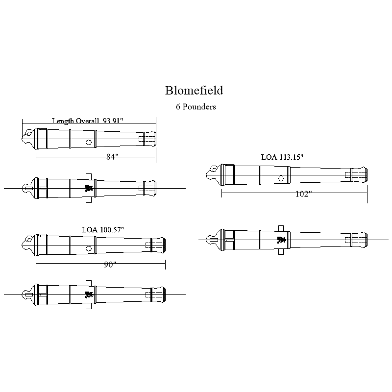
Tim,
Were Blomefield cannon on Speedy as well as the carronades? If they were indeed Blomefields, you can take the STL drawing to any 3D printer and tell them the dimensions that you want and they can scale to size and print them black resin for very little cost. I also attached the 2D below to give you an idea of the actual shape of the cannon of that era.
Allan
12 pounder Blomefield pattern WITH George the 3rd BADGE (1).stl.glb
-
Hi 3Bs
This is very interesting, thank you for sharing. Can you say where you got the plans for the USS New York?
For the future, if you have not already done so, there is a ton of great information to study on proper planking in the articles data base here at MSW, (https://thenrg.org/resources/Documents/articles/APrimerOnPlanking.pdf) and in a four part video
https://www.youtube.com/watch?v=KCWooJ1o3cM by Chuck Passaro that you may like.
Allan
-
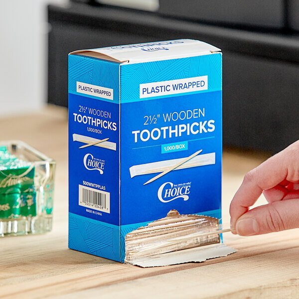
Now I understand why they all are identical. That in itself is a great achievement.
Sorry if I missed it, but is the toothpick wood or plastic or some other material? From the photo it is hard to tell but it looks something like those in the picture below.
Thanks!!
Ciao
Allan
-
-
6 hours ago, glbarlow said:
All of us Winchelsea builders are familiar with this and following Chuck’s instructions have thinned the wales at the bow
Hi Glenn,
You and the Winnie builders are among a lucky (and well informed) group.😀
I still wish someone could find a written description, especially if based on contemporary information describing this feature. It is an obvious feature on contemporary models, but it would be great to see this described in old documents.
Allan
- mtaylor and thibaultron
-
2
-
5 hours ago, DaveBaxt said:
The only problem I have been informed is that they are probably still slightly to thick and therefore I have been advised that it is better to not overlap them.
I totally agree, but thankfully with the nail punches they have they will appear to overlap unlike the original ones that came with the kit.
Allan
-
It is great to see the new Amati plates looking like small nail punches instead of the gigantic rivets. Hard to tell if they overlap but no matter as they do appear to be shingled properly rather than laying side by side what with having a single row of nails showing on each side. Very good call to make the switch David
Allan
-
When I originally made the drawing above in 2010 it was for the Euryalus (1803) so the rounding, if any, may have been different for Revenge (1577). The height of the head ledges and coamings definitely varied over the years, getting higher above the deck as time went on but I cannot find anything based on contemporary sources regarding the rounding itself. Not the most important thing in a build, but might be interesting to some.
Allan
-
Welcome to MSW Ching
You may want to give your location for those that might be interested in your services as we have members from all over the world.
Allan
- Keith Black, mtaylor and JeffT
-
3
-
-
I typically dye the wales with black ink ahead of time but invariably have to touch up, including where the wales are thinned at the bow. I have used holly for decks but not on the hull so this act differently. I typically use Castello with no issues. For touching up, first step is to seal the strakes above the wale and black strake, and the thick stuff below the wale with whatever finish I will be using later. This is usually an egg shell finish clear coat. Then a little tape over that once the clear coat is dry and fresh ink where it needs to go. I little fuss, but no muss.
Allan
- thibaultron, mtaylor and scrubbyj427
-
3
-
9 minutes ago, Jaager said:
Ouch! as far as accomplishing this.
Hi Dean
Do you mean finding the information or performing the task? 😀 Performing the task is pretty simple. I usually just thin the last 1/4" or so to the proper thickness so it will seat in the rabbet and leave some room to work once glued and treenailed in place. Once all the planking is done I have room to file and sand the heavier strakes as needed.
Allan
- thibaultron, DaveBaxt and mtaylor
-
3
-
This subject has been discussed lately in several build logs as this feature appears to be missing in many builds, kit and scratch both. One of our astute members suggested posting this in this forum as well as the logs where this was discussed.
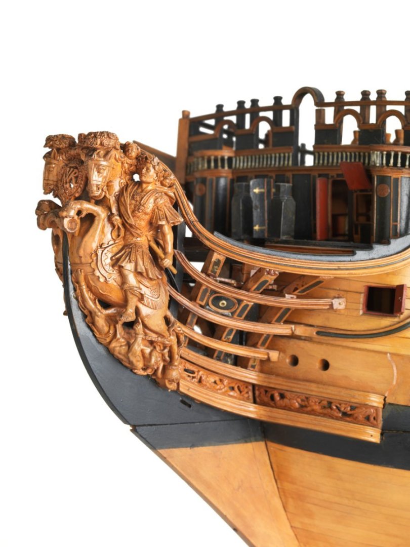
What precipitated this discussion for me many years ago had to do with the fact that unless the wales and thickstuff was thinned at the bow it could not seat normally in the rabbet. While the shape of the rabbet is dynamic it is not stepped to allow for different thickness plank ends so the thick planks such as the wales and the few strakes of thick stuff above and below the wales have to diminish. There are photos of contemporary models where this can be seen, but I have never found mention of this in any books that I can remember or, in the case of English ships, the Establishments or the scantlings in The Shipbuilder's Repository or The Elements and Practice of Naval Architecture by David Steel. The lower wale of a 50 gun ship built to the Establishments of 1719 through 1750 was 5.5" thick. The strake above and below was 4" thick. The plank below the thickstuff was 3" thick. Wales and thickstuff should taper to 3" thick at the rabbet.
If anyone has any contemporary based information on this subject, that would be great to see. Photo below is the Royal William (100) 1719 showing the wale being the same thickness as the thickstuff and plank of the bottom at the rabbet. The thinning seems to begin at about the area of the cant frames. Based on the 1719 Establishment her lower wale would have been 10" thick, the strake above 8" thick and the seven strakes below the wales starting at 8" thick and ending to match the plank of the bottom which was 4" thick. This was a diminished thickness of 6 inches for the wale.
Allan
- scrubbyj427, Thukydides, mtaylor and 5 others
-
6
-
2

Question on quarterdeck bulwark inside belaying points of English 74
in Masting, rigging and sails
Posted
Mitsuaki
I agree with Dean, the holes for the pins in the first photo in post #4 above look much too large. For some great information on making belaying pins take a look at the Euryalus build log by Matiz. https://modelshipworld.com/topic/24583-hms-euryalus-by-matiz-scale-156/page/9/#comments, posts #252, 253, and 254 as well as the photo from his log below. He made all his pins to scale.
Allan