


allanyed
-
Posts
8,110 -
Joined
-
Last visited
Content Type
Profiles
Forums
Gallery
Events
Posts posted by allanyed
-
-
-
-
14 hours ago, Bob Fraser said:
Kaolin and Morphine over the counter for upset stomach. People were getting hooked on it as it was cheap until the Morphine addiction was realised and it was banned!
And cocaine in Coca Cola..... ahhh the good ole days. Found the following which may be made up as to quantity but funny none the less
“The first bottles of Coca-Cola from 1894 contained around 3.5 grams of cocaine, explains why our grandparents could walk to & from school, uphill, both ways, in the snow, barefoot.”
-
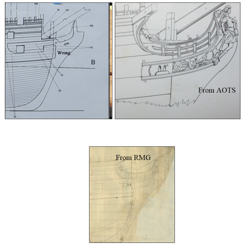
For some years prior to copper sheathing the bottom was coated with what I believe was a mixture of pitch and tallow and this was possibly applied liberally over everything below the water line, including the pintles and gudgeons (the banding you mention). To the contrary, the beautiful paintings of 17th century ships in The Master Shipwrights Secrets show the pintles and gudgeons darker, but these are modern paintings rather the contemporary. A search of contemporary models on the RMG Collections site might show some examples for you to consider.
For the future, maybe take a look at contemporary drawings to get an idea of the size and design of real pintles and gudgeons. As you know there were recent posts in https://modelshipworld.com/topic/33530-frigate-diana-by-rossr-occre-185/page/3/#comment-996293 regarding the sizes and such of these rudder components and how to accurately depict them at various scales.
Allan
-
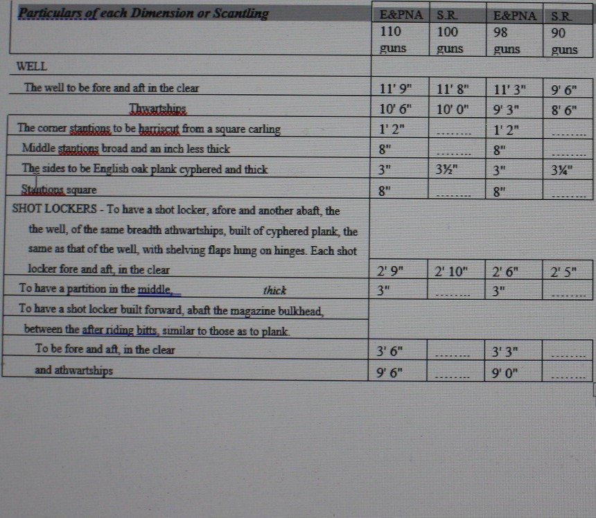
A little more info from the scantlings book.
- Darius359au and mtaylor
-
 2
2
-
Hi Darious
Have you looked at the contemporary inboard profile and orlop deck plans of Victory on the RMG Collections site? Each drawing has a scale so you can get a measurement then adjust for whatever scale your model is. https://www.rmg.co.uk/collections/objects/rmgc-object-79912 and https://www.rmg.co.uk/collections/objects/rmgc-object-79914 These are low resolution so it may be a little difficult, but they are free. If you are going into that kind of detail you may want to consider purchasing the high res plans from RMG. These are from when Victory was launched in 1765 so there may be differences, but you can also get the well and shot locker dimensions for first rates in Scantlings of Royal Navy Ships on pages 117 and 118. These dimensions are taken from The Shipbuilder's Repository 1788 and Steel's The Elements and Practice of Naval Architecture, 1805.
Allan
-
17 minutes ago, Jaager said:
Go to the RMG site.
enter ZAZ1357
Dean points out a great drawing as Dragon is a sister to Bellona. This drawing can also be found in very high resolution in the WikiCommons site. https://commons.wikimedia.org/wiki/Category:Ship_plans_of_the_Royal_Museums_Greenwich It is 127.6 mb so does not attach here.
Allan
- thibaultron, druxey and mtaylor
-
3
-
4 hours ago, Nearshore said:
i am not understanding the plank directly under the gun ports. It is showing the thickness of that plank being 0.6mm.
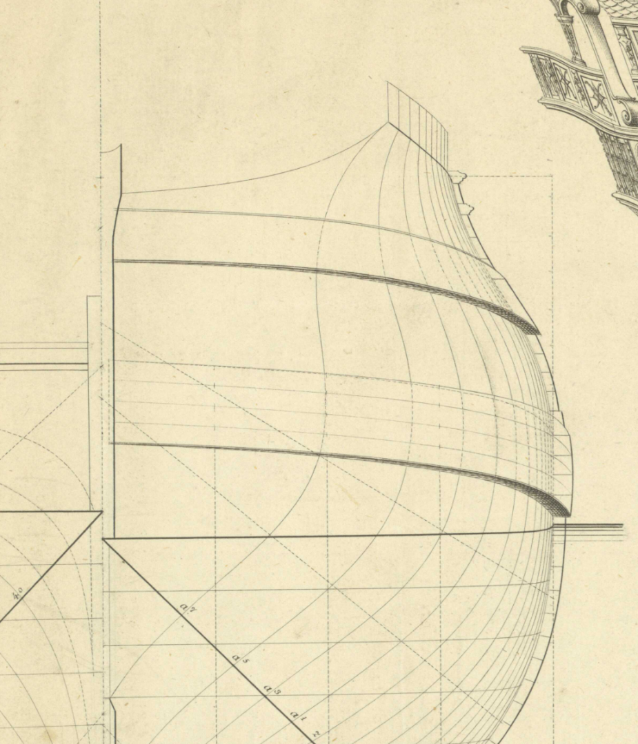
Based on the scantlings for a 74 in both the Shipbuilder's Repository 1788 and Steel's The Elements and Practice of Naval Architecture 1805 the lower wale is made up of four strakes of planking. They should be about 10 to 12" wide (0.1" at your scale of 1:100) which makes it about 40 to 48 inches wide in total. These were likely made up of anchor stock planking, not straight pieces, but that is for another day. The SR, gives a thickness of 8.5" and the EPNA gives a thickness of 8". At your scale of 1:100 the total width is thus just under 1/2" wide (10-12mm) and 0.08-0.085" thick (2mm) . The planking below are gradually thinner, reducing over several strakes to 4", or 0.04" thick (1mm). The strake above the main wale is the black strake and is about 6.5 to 7" thick. The strake above the black strake is 5"thick. Both are 12" broad. I hope this makes some sense. Hopefully the following sketch will help a little
Allan
- druxey, mtaylor and thibaultron
-
3
-
Lots of progress, she is looking good!
Have you looked at the posts on the reducing of the thickness of knee of the head? It is a long string with many comments, but worth the read, especially the post by Chuck Passaro https://modelshipworld.com/topic/34577-taper-of-the-keel-stem-knee-of-the-head-and-stern-post/
When you go to add the wales, note that the drawing in post #36 is not as seen on contemporary models or plans as the wales should be diminished in thickness at the bow in order to seat properly in the rabbet. There is a good discussion on this at https://modelshipworld.com/topic/34868-wales-diminishing-thickness-at-the-bow/
Allan
-
3 minutes ago, Jaager said:
At the stem rabbet and sternpost rabbet the run should be near horizontal
This is key to avoid the look of a Viking ship hull. As has been suggested many times by many members, study the tutorial by David Antscherl on planking in the Articles Data Base here at MSW and the four part You Tube video by Chuck Passaro . Both methods work well. If you are making planks from sheet stock spiling is great. If you only have precut strips that are the same width from one end to the other, follow the steps in the videos by Chuck. For more information look at a few planking expansion drawings to get an idea of the shape of planking at RMG Collections. https://www.rmg.co.uk/collections/objects/search/planking expansion
Allan
-
1 hour ago, GrandpaPhil said:
A pounce wheel works well for embossing nail heads
The Excel 7/16" stock wheel with 14 points would be very close for marking the spacing of the fixture at 1:85 scale. As the straps were secured with a combination of screws and bolts, the pounce wheel may not be a good idea for other than marking the spacing though as one or two would be bolt heads on each pintle strap and the other indented like screws. Just like the pintles the gudgeons were sometimes secured to the hull with a combination of screws and bolts but sometimes only with bolts.
There is a lot more to the shape and taper in thickness but at 1:85, probably not so noticeable.
David Antscherl gives a lot of really good detail on these in volume II of TFFM.
Allan
-
Hi Rick
Sounds like it should do the trick for you. Please post pics of the end results. I looked at the Excel pounce wheels on Amazon and the small (1/4") wheel does 24 points per inch so really close to the spacing for your scale on the one long and one short row at the two outer edges and the larger wheels look good for the punch marks in the center row. They quote a 2 day delivery so really good.
Allan
-
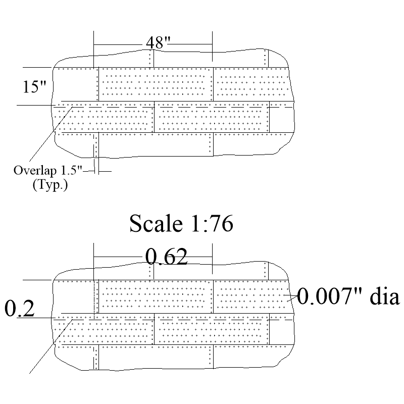
Are you planning to use this for copper sheathing? If that is the case, keep in mind that the sheathing never had rivets, but rather 1/4" nails with about 0.5" heads spaced a couple inches apart. Depending on your scale, these will be from near invisible to the tiniest of dents. They should never stick out as seen in some modern models. Look at the copper sheathing from Vanguard and newest ones from Amati that Dave posted in his log.https://modelshipworld.com/topic/34080-hms-diana-1794-by-davebaxt-caldercraft-164/page/5/ post #127, third photo down.
Hopefully the following sketch will help. If you are referring to your current build of the USF Essex 1:76 scale, the dimensions show full scale and 1:76
Allan
-
The enlargement below might help as well. Thanks for posting this Martes!! It is very clear that the thickness is diminishing, and seems to be slightly thicker than the surrounding strakes at the rabbet. That being the case, how does it sit in the rabbet? Must it be carved to sit in the rabbet with a little sticking out or is the rabbet chiseled to accept the full thickness of the end of the wale? I realize at our scales this will be barely, if at all, noticeable.
Allan
- mtaylor and thibaultron
-
2
-
On 7/19/2023 at 3:57 PM, James H said:
Yes, the plans have this detail, should the modeller wish to do it. It would be up to them.
Thank you Chris. The drawing you posted is SUPER.
What I am curious about is whether all yards on all rates up to and including royals, had this feature on the actual ships.
Interestingly I found that this design did not start until circa 1690. The British started making the large spars from two pieces scarfed together from 1773. In that case, 8 battens were used in the mid quarter rather than the 8 sided shape of the spar itself. For modeling purposes, the use of battens may be an alternative to get the look of the octagon.
Allan
-
On 7/19/2023 at 5:54 PM, RossR said:
I do not own a drill press, so I am not very confident that I could drill the small holes in 1.2mm material with a hand held drill.
Thinking about this a bit further, when working at the small scales like your build, you might want to forget drilling holes and just epoxy the pintles and gudgeons in place if you use copper or plastic or brass parts or pva glue if you use card stock. In either case, once they are secured in place you can use a needle tip to make tiny bolt heads on the straps by dipping it in glue and making the requisite number of dots on the straps and a clean needle tip to make dents representing screws. For the bolt heads I make a small puddle of PVA and add a tiny bit of black acrylic paint so it does not have to painted once set. It does not take much but a little experimenting will help.
Allan
- RossR and GrandpaPhil
-
1
-
 1
1
-
13 hours ago, Gregory said:
You might consider card.
Great suggestion. I agree that in this case it is good to pin the rudder in place. IF you want the rudder to be able to turn, then working metal parts are best. A last alternative is to draw the parts in 3D and have them printed in 3D. These could be the most realistic looking parts at smallest scales if drawn accurately.
Allan
-
The finish on your hull planking looks very nicely done! Regarding the wales at the bow in the pictures in post # 12 above, you may want to see a recent discussion on the tapering of the thickness of the wales. https://modelshipworld.com/topic/34868-wales-diminishing-thickness-at-the-bow/
Thanks for sharing your build!
Allan
-
Hi Aydingocer
This is great as you show a very clever way to do this with a simple tool such as your drill.
Do the yards on a sixth rate have an octagon center quarter? The octagon shape in the center quarter of the yards started about 1690 according The Masting and Rigging of English Ships of War, page 13 but Lees does not say if all yards on all rates had this design feature after 1690 so I am curious. Volume IV of TFFM by David Antscherl describes the octagon on the yards of a 14 gun sloop. If they do take this shape, it is probably easier to make the octagon at the maximum dimension needed, then sand as you have clearly shown leaving the center quarter as an octagon.
Allan
- mtaylor and aydingocer
-
2
-
Do not be too hard on yourself, it is obvious you are making a great effort to get things right and are to be congratulated for doing so.
Allan
-
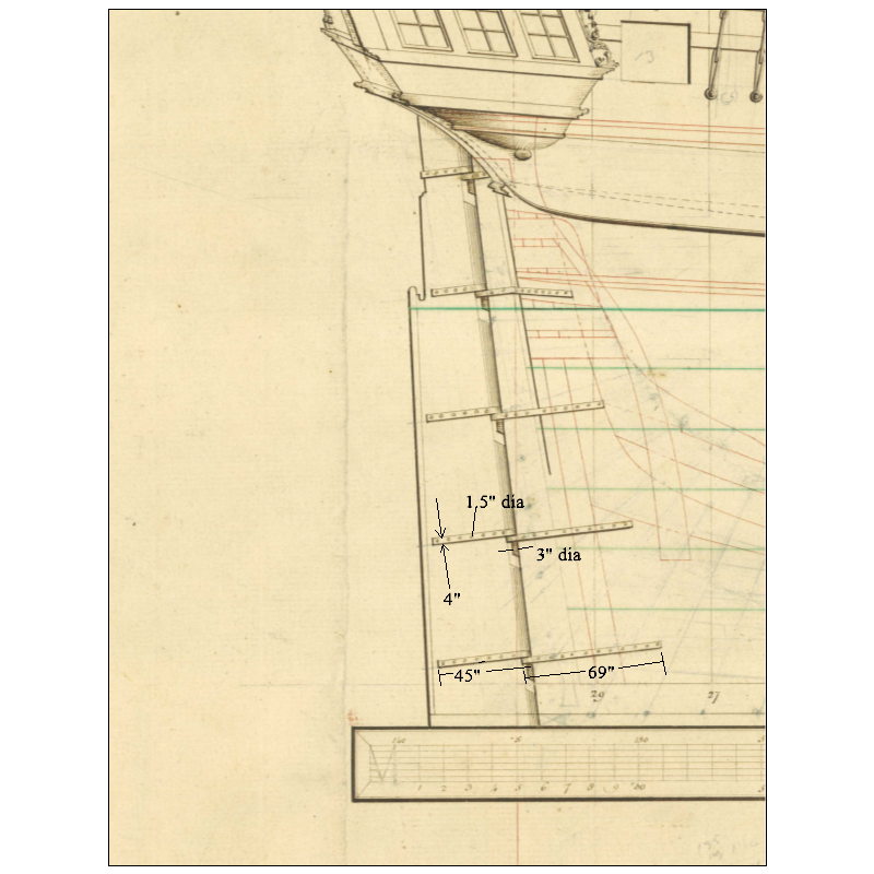
The pintles and gudgeons are fun little projects to practice soldering techniques, congrats for giving it a go! If not too late, or for the future, the below shows the approximate sizes of the various parts and number of bolts on a typical 32 gun British ship in the 1790s. I suspect the Spanish ships would be similar. For your scale of 1:85, the straps would be 0.047" (1.2mm) wide, the pin would be about 0.035" (0.9mm) and the bolt heads would be about 0.018 (0.45mm) Note the lengths of the straps and the number of bolts as well. I show the dimensions of the lower one, but you can size the rest using the scale to get an idea of their respective lengths. For the lower ones at your scale, they are about 0.53" (13.5mm) and 0.81" (20.6mm) The materials used were typically copper or iron. If you use copper you can blacken them once installed with liver of sulfur to represent iron or leave them clean to show as copper. Again, it may be different for Spanish ships, but this information should be close.
Allan
- DaveBaxt and GrandpaPhil
-
2
-
Barring the possibility of a personal visit to Mystic, try https://mysticseaport.org/contact-us/ Using the number on this site you may want to call them first to get pointed to the proper person that will be able to help you rather than just sending a written enquiry.
Allan
-
Welcome Geoff, glad to have you aboard!
Allan
- Keith Black and mtaylor
-
2
-
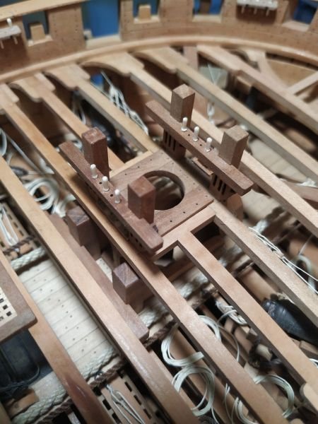
6 minutes ago, Jaager said:
It may be an artifact from the photography, but the holes for the pins look to have about twice the probable diameter.
Mitsuaki
I agree with Dean, the holes for the pins in the first photo in post #4 above look much too large. For some great information on making belaying pins take a look at the Euryalus build log by Matiz. https://modelshipworld.com/topic/24583-hms-euryalus-by-matiz-scale-156/page/9/#comments, posts #252, 253, and 254 as well as the photo from his log below. He made all his pins to scale.
Allan
- mtaylor and fake johnbull
-
2


Charles W Morgan by ESF - Model Shipways - 1:64
in - Kit build logs for subjects built from 1801 - 1850
Posted
Just joined the party and happy that I did. She is looking really fine Steve!
It appears that you tapered the knee of the head, which is fantastic. Was this part of the kit instructions or was this based on your own research?
Allan