


allanyed
-
Posts
8,149 -
Joined
-
Last visited
Reputation Activity
-

 allanyed got a reaction from IgorSky in SHIP'S WHEEL
The above answers your question but I must comment on the drawing you posted. You are right, the quality is a bit off. How can the ends of the line wrapped around the drum both drop from the same side of the drum? Reminds me of some far out designs in Mad Magazine back in the day like the 2/3 tined fork in the attached picture.
Allan
-
 allanyed got a reaction from Jack12477 in Another rookie question - Can I Clean Up the Keel With A Dremel
I agree with the above. Rotary tools have their place, but this probably is not the place. You can shave a thousand of an inch with a chisel. I defy anyone to do that with any consistency with a rotary drum.
Allan
-
 allanyed got a reaction from mtaylor in Another rookie question - Can I Clean Up the Keel With A Dremel
I agree with the above. Rotary tools have their place, but this probably is not the place. You can shave a thousand of an inch with a chisel. I defy anyone to do that with any consistency with a rotary drum.
Allan
-
 allanyed reacted to JerseyCity Frankie in Pin Rails
My two or three cents about pins and pinrails: Use the smallest possible pin you can find or make, this will prevent a cascading series of scale issues from developing later. Obviously the smaller the pins, the more can be fit on a rail. Every pinrail I have seen has the pins spaced evenly about 10" apart. Any closer together and the belayed lines passed around the pins would interfere with each other and the sailors couldn't get their hands in there.
Most of the pins I see on models are too big and have en exaggerated shape and if scaled up would look like three foot high wooden lightbulbs. Most actual pins are two inches wide at most and are seldom longer than 18". They do flare out on their upper halves, but only a bit and a human hand can still grasp them- the commercially available ones all too often flare out into nearly spherical globes. Also consider that once there is a line on the pin, the pin itself is no longer visible except maybe its very top. For this reason I mostly just use wire or rod.
An issue that always arises is the apparent low number of pins, modelers often find their accurate plans do not provide enough places for all the lines to belay to. This is a very common problem.
As mentioned above, another very common problem is not fixing your pinrail strongly enough. There isn't very much tension on them but the pinrails on models do very often pull out or distort from the accumulated strain placed on them by the rigging, which apparently over time can contract.
-
 allanyed got a reaction from Jason in The Restoration Warship - Richard Endsor
I bought this book as a reference to my current project, but have to say, it is a delight to read from many views. It is based on the Lenox (70 gun) which was the first of the 30 ship building program of 1677. Anyone interested in the construction of ships from the late 17th century into the 18th century would be extremely happy to have this book as a reference and for a very interesting read in general.
Richard Endsor has provided a great deal of history, his own drawings and paintings, many drawings by Willem Van de Veld the Elder and others, photos and more. Richard was educated as an engineer and his attention to detail inherent with most engineers shows through, but his talent as an artist is something not to be missed.
I can go on and on but suffice it to say that I am extremely pleased to have this in my library.
Allan
-
 allanyed got a reaction from hornet in The black stripe
Marty,
Pages 57 and 58 in Goodwin's Arming and Fitting give a lot of information on paying the hulls, The description he gives is of tallow, rosin, sulfur, oil from whales and seals, and pitch, no mention of lead at that point. The black stuff was half the price of white stuff and became predominant over white stuff by 1702, but mostly on ships in home waters. The white stuff was thought to be superior and was used for the supposedly more demanding waters of the Caribbean and Mediterranean Seas.
When brown stuff came into use later in the eightheenth century, it was used from keel to about 3 feet below the LWL. The next three feet were payed with tallow and lime and had a skirting of white lead and tallow.
Allan
-
 allanyed got a reaction from druxey in The black stripe
Marty,
Pages 57 and 58 in Goodwin's Arming and Fitting give a lot of information on paying the hulls, The description he gives is of tallow, rosin, sulfur, oil from whales and seals, and pitch, no mention of lead at that point. The black stuff was half the price of white stuff and became predominant over white stuff by 1702, but mostly on ships in home waters. The white stuff was thought to be superior and was used for the supposedly more demanding waters of the Caribbean and Mediterranean Seas.
When brown stuff came into use later in the eightheenth century, it was used from keel to about 3 feet below the LWL. The next three feet were payed with tallow and lime and had a skirting of white lead and tallow.
Allan
-
allanyed got a reaction from druxey in Artillery drills on period ships
I really like the breeching line laying on the deck. Good thing they used a light load or that piece would have rolled until it hit something solid enough to stop it, hopefully.
Allan
-
 allanyed got a reaction from jaerschen in HMS Triton 1773, 1/48, POF by Juergen
Juergen,
I like the fix a lot. Great job! And no one but those of us that saw your photos will ever know!
Allan
-
 allanyed got a reaction from janos in Preferred type of Boxwood
Richard,
From a practical standpoint (cost and availablity) I choose to use Castello ( Costello) for the bulk of the pieces that go into a model for the many good reasons given in a number of previous posts and topics. I do prefer European boxwood for carvings. Even small (2" diameter) logs can be used and two or three short pieces can last for years. The yellow will darken over time as will most of the woods used in our models.
Allan
-
 allanyed got a reaction from Jaekon Lee in HMS Alert 1777 by Jaekon Lee - 1/64
Hi Lee,
Your workmanship is obviously terrific, but I have a question. Assuming there are no gun ports, the sides of which the frames would form, why are there filler pieces, offsets, and dog legs in some of the futtocks? I understand the siding of each futtock reduces as you go up, so there would be a step at the butts, but I cannot figure out a reason for the other shifts of the futtocks. Again, your workmanship is very good, but I would like to understand the whys of the dispostion of the frames.
Thank you
Allan
-
 allanyed got a reaction from tasmanian in Preferred type of Boxwood
Richard,
From a practical standpoint (cost and availablity) I choose to use Castello ( Costello) for the bulk of the pieces that go into a model for the many good reasons given in a number of previous posts and topics. I do prefer European boxwood for carvings. Even small (2" diameter) logs can be used and two or three short pieces can last for years. The yellow will darken over time as will most of the woods used in our models.
Allan
-
 allanyed got a reaction from robcg in how to determine the correct number of frames on scratchbuilt ship (Moved by moderator)
Bud
If you can tell us the name and size of the ship as well as the year, the sidings of the floors and futtocks as well as room and space can be determined. From these you can determine the number of frames. Are the stations shown on your drawings?
I am doing a framing disposition drawing of the Litchfield (50) 1730, built to the 1719 Establishment now, so can share the issues in having the frames form the sides of the ports etc. Do any of your existing drawings show the gun port locations?
Allan
-
allanyed got a reaction from druxey in how to determine the correct number of frames on scratchbuilt ship (Moved by moderator)
Bud
If you can tell us the name and size of the ship as well as the year, the sidings of the floors and futtocks as well as room and space can be determined. From these you can determine the number of frames. Are the stations shown on your drawings?
I am doing a framing disposition drawing of the Litchfield (50) 1730, built to the 1719 Establishment now, so can share the issues in having the frames form the sides of the ports etc. Do any of your existing drawings show the gun port locations?
Allan
-
allanyed got a reaction from mtaylor in Modelling magazines (Moved by moderator)
Medic
There used to be and maybe there still are one or two. I have not seen any in many years that actually help building models the way this site does. Even those that were out there cannot compare to the information you get at this site. You will get more new information from this site in a day than you will find a year's worth of magazine articles. The building logs alone give more tips on how to than a magazine. AND, if you do not understand a particular item, you can ask and get answers very quickly.
Allan
-
 allanyed got a reaction from dgbot in Modelling magazines (Moved by moderator)
Medic
There used to be and maybe there still are one or two. I have not seen any in many years that actually help building models the way this site does. Even those that were out there cannot compare to the information you get at this site. You will get more new information from this site in a day than you will find a year's worth of magazine articles. The building logs alone give more tips on how to than a magazine. AND, if you do not understand a particular item, you can ask and get answers very quickly.
Allan
-
 allanyed got a reaction from WackoWolf in Modelling magazines (Moved by moderator)
Medic
There used to be and maybe there still are one or two. I have not seen any in many years that actually help building models the way this site does. Even those that were out there cannot compare to the information you get at this site. You will get more new information from this site in a day than you will find a year's worth of magazine articles. The building logs alone give more tips on how to than a magazine. AND, if you do not understand a particular item, you can ask and get answers very quickly.
Allan
-
 allanyed got a reaction from NHDave in Scissors for getting early close cuts of rigging ties and knots
I have used the same barber shears for years. The best go for $500 to over $1000, but are meant for thousands of snips per week. I found a pair with convex edges for $80 that will last a couple lifetimes of rigging without having to be sharpened. These were $200 shears that I bought at a cosmetics and hair trade show in the last hour of the last day. I can CUT, not tear even the tiniest strand right at the knot without having to have any tension on the piece being cut.
In the end, quality comes with a price as is usual.
Allan
-
 allanyed got a reaction from DBorgens in Mast Partners for Swan Class ships
While the dimensions are not necessarily correct for your ship, this may give a better understanding of the marriage of the partners and surrounding beams and carlings.
Allan
-
.thumb.jpeg.fc5d633a7b34428fcf19419a73d56d55.jpeg) allanyed got a reaction from EricWilliamMarshall in Royal Navy Fireship COMET 1783
allanyed got a reaction from EricWilliamMarshall in Royal Navy Fireship COMET 1783
I had the privilege to preview this book and see the model while under construction and I can say that it is a must for any scratch builder or kit basher. There are a lot of new areas covered that are not to be found in the TFFM series such as an extremely detaled description on building the galleries, not to mention the design and construction of a ship with the specific purpose of being a fire ship.
I was supposed to be proof reading for errors but I became totally engrossed in the text and illustrations and enjoyed the read as much as I found an appreciation for its usefulness to the model builder.
Allan
-
 allanyed got a reaction from hexnut in Effie M Morrissey 1894 by allanyed - FINISHED - Scale 1:48
The deck beams are coming along. The pattern on the plans is odd in at least one place. The photo 9-13-13B of the deck beam locations has a black arrow showing what I mean. This may be a result of one of the refurbishments made since she was originally launched. There are also more typical uses of heavy beams, narrow beams, carlings and ledges, lodging knees and hanging knees. The mast partners are relatively simple designs. The hanging knees are in fact hanging standards as they fay to the bottom of the beams, not the sides of the beams.
I added a few of the knees where I plan to leave a bit of the deck uncovered. I am also installing the after cabin bulkheads and deck as I may leave the sliding cover open. There will also be a ladder going from the weather deck down to the cabin deck.
Allan
-
allanyed got a reaction from hexnut in Effie M Morrissey 1894 by allanyed - FINISHED - Scale 1:48
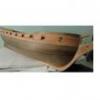
The hull planking is on and first sanding complete. Hand sanding to a fine finish will be next. I left a section of planking off to expose the framing, but I have decided against installing most of the below deck items inside the hull. I left a little DNA on the keelson after a little slip of a chisel, so there is no denying who built this thing.
I put in a few inside planks for strength and the two mast steps are in place. The deck frames are started. There are a few carlings where there are deck structures and to set up the masts' partners. Once the deck is framed the stanchions and bulwarks will follow.
Allan
-
allanyed got a reaction from EricWilliamMarshall in Effie M Morrissey 1894 by allanyed - FINISHED - Scale 1:48
A bit of progress on Effie. The deck is planked and scraped, but needs a bit of trimming around the various deck openings. With no top timbers on the frames, sanding and scraping the deck planking was easier than when there are bulwarks or top timber framing in place.
There are stanchions between frames versus having top timbers on the frames. The frames stop at the same height as the top of the deck beams so the stanchions will be the support for the bulwark planking.
When framing the model I placed small blocks between frames to give added strength. Coincidentally, these act as a stop for the stanchions. I have drawn these blocks in red on the attached.
I have started fitting filler decking pieces between the stanchions to close in the decking around the stanchions as shown on the photo.
Allan
-
 allanyed got a reaction from rdsaplala in Mast Partners for Swan Class ships
Peter Goodwin gives a rather detailed explanation and provides sketches of the use of the wedges in his Construction and Fitting of the English Man of War on pages 169 and 171.
The opening area inside the partners is about 10" to 12" larger than the diameter of the mast thus the wedges are about 5 or 6 inches thick where they contact the mast and partners. The corner chocks are dressed to the appropriate diameter, but he does not say or show the carlings or cross partners being dressed to form a circle. He does say that many of the wedges had to be made "tailor made".
Allan
-
allanyed got a reaction from mtaylor in Mast Partners for Swan Class ships
While the dimensions are not necessarily correct for your ship, this may give a better understanding of the marriage of the partners and surrounding beams and carlings.
Allan