Javelin
-
Posts
638 -
Joined
-
Last visited
Content Type
Profiles
Forums
Gallery
Events
Everything posted by Javelin
-
 From someone who made the same mistakes (see topic on LPG tanker Chaconia), I can give you one advice. Either start over on that hull starting from the beginning and make those frames again, but perfect this time. Or, less optimal, carry on, the way you are going now, but continue with filling and sanding untill it truly is perfect. Use primer layers to spot the bumps and dents. I do fear the wobly hull will always show through though. Filler can only do so much. The reason I'm saying this, is that such ships are a long process and your skills evolve during construction. In the end you're building good details etc, but still on a less-than-perfect hull, and it's going to bother you, believe me 🙄. That said, at least you took on a rare scratchbuild project and got started (that's better than 99.9% of people). If you finish it, people will certainly admire it, unable to understand how you pulled it off.
 -
Beautiful work Phil, these different colored details really stand out and make the real difference between a good model and an excellent model!
- 492 replies
-
- 2
-

-
- minesweeper
- Cape
- (and 1 more)
-
Not talking about booms for lowering the boats, but booms for entering them. Like ones seen on HMS Formidable here: HMS Formidable Sailors would crawl along the boom to the ladders length towards ladders, the boats would be moored side by side along the boom below the ladders. As mentioned I'm not entirely sure. You also see the boom on Formidable is mounted on the hull side rather than on deck. But I don't think it's impossible.
-
Given their position in relation to the boats's position, I'd also say they are the booms to moor and embark the boats. They also seem to be long enough to serve that purpose. Regarding rigging to deploy and stow them, no idea. Perhaps connected near the upper stowage support?
-
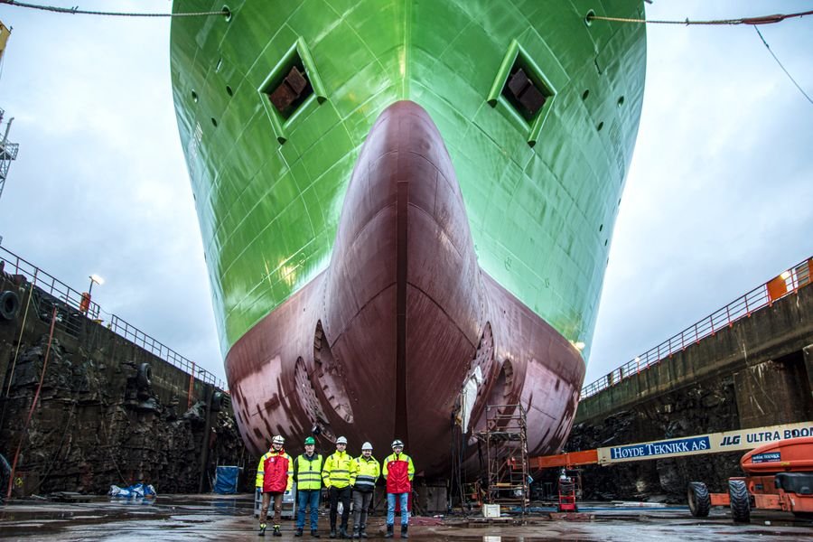
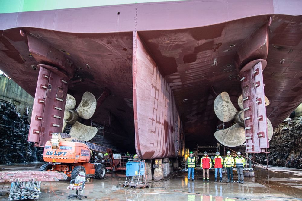
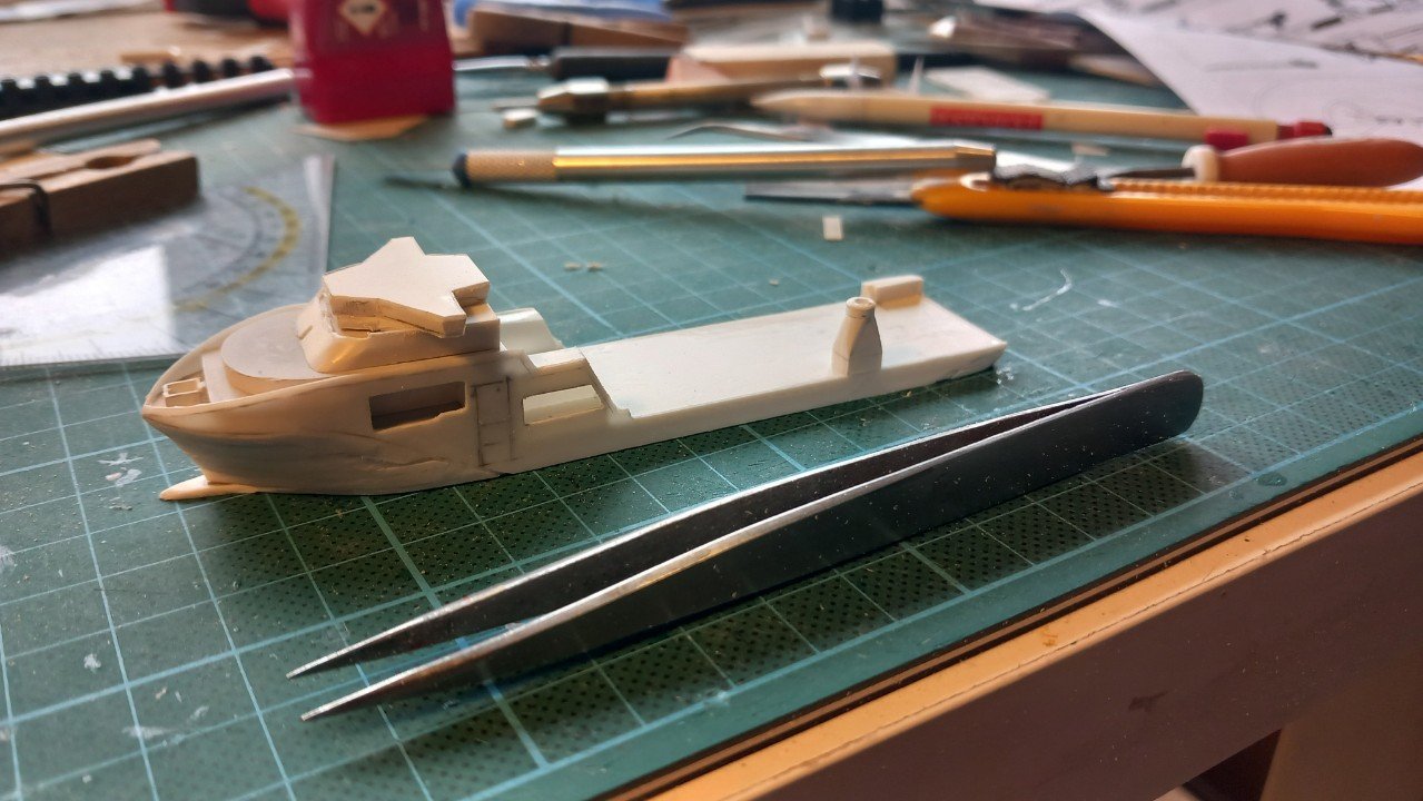
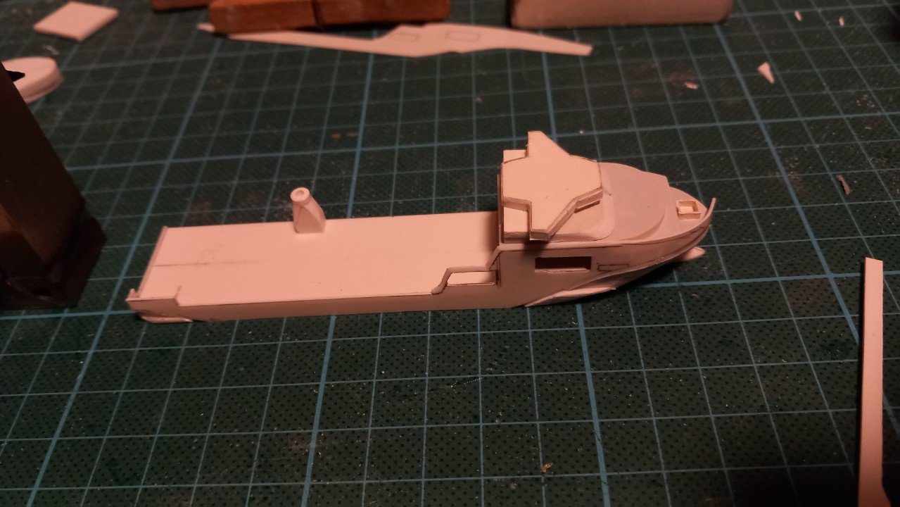
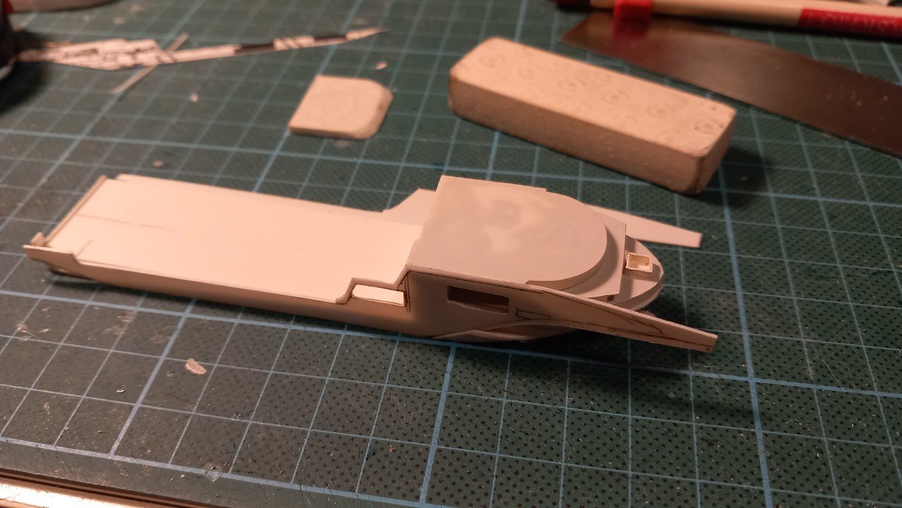
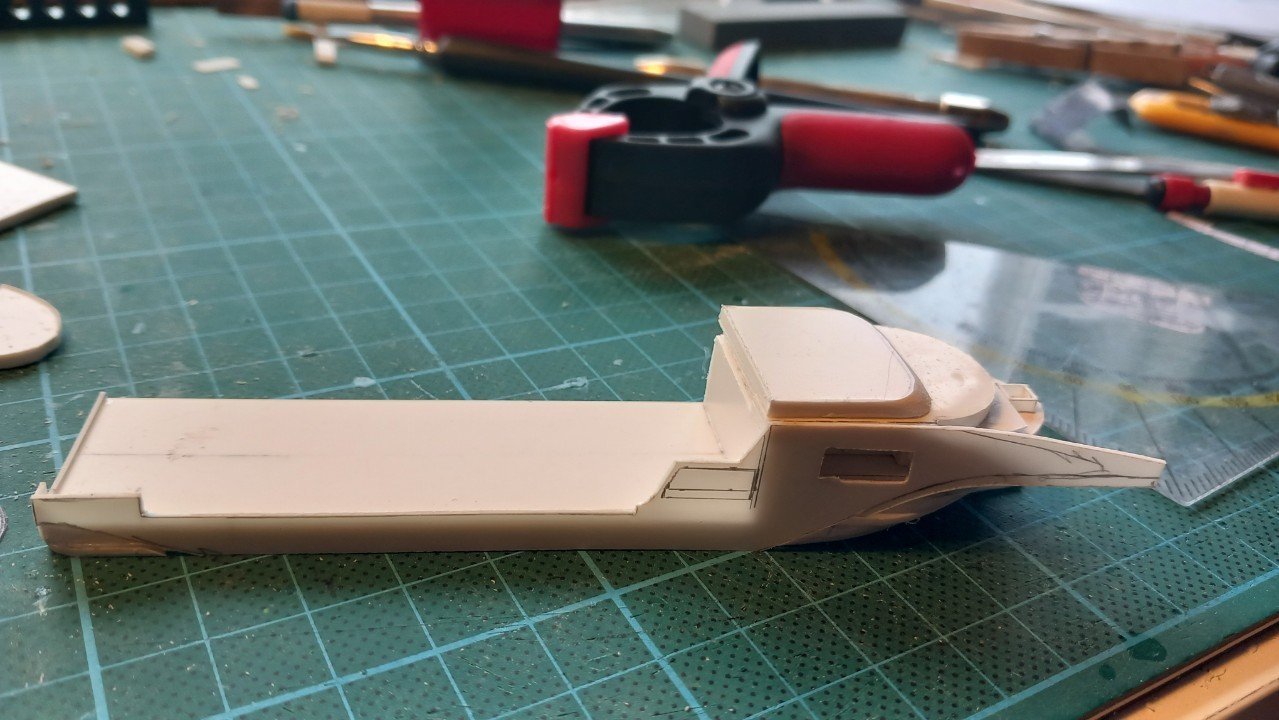
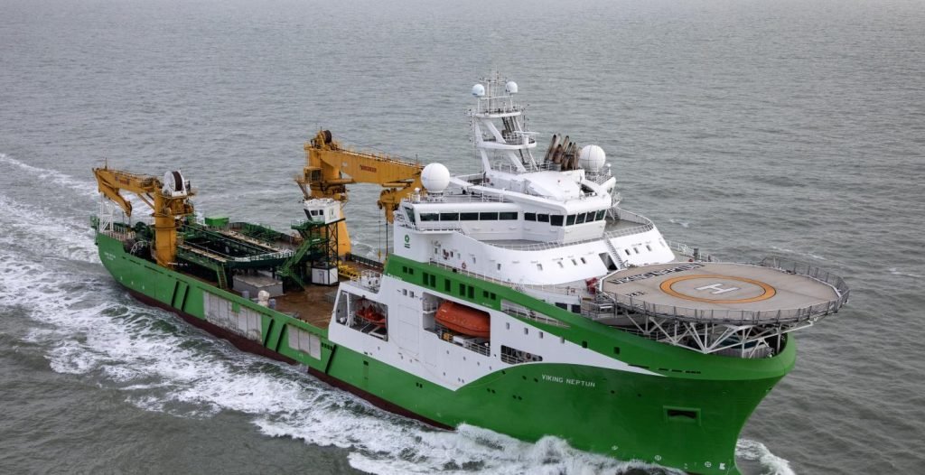
Thanks Paul. A litte more about that real ship. This is not relevant for this build, since this is a waterline model. (perhaps for a future racecar red version?). What makes her somewhat special for a modern offshore DYnamic Positioning vessel is her rather conventional propulsion. Where most vessels in these classes are relying purely on azipods/twin pods etc. Basically propellors that can be turned 360°, Viking Neptun has a conventional twin propellor-twin rudder propulsion. In addition, she has 2 regular bow thrusters, 3 stern thrusters and just behind the bow thrusters, 2 retractable azipod thrusters. That's a lot of power and thrusters to hold position and heading. You don't want to tangle lines 2km below the waterline... As mentioned, a lot of them are simply redundant, so that in case of failure of one thruster, or a complete power production unit, she can still maintain that position and heading. As a disadvantage, this means all engines and thrusters need to run during DP operation, which means the engines are continuously running at very low power, which they really don't like. In above picture you can see the rudders are of the Becker type, which means there is an additional piece that hinges in the same direction as the rudder, this doubles the effect of the rudder, so a 10° rudder angle on this type of rudder equals a 20° angle on a normal rudder. They can also often be used at greater angles, creating a nearly 90° deflection. The propellers are variable pitch propellors, the blades can rotate hydraulically, to change the thrust while keeping the same rpm. This means they are less efficient (compared to fixed pitch) for pure sailing, but makes the vessel much easier to manoeuvre. As for the model, this may be the last post for a while as I've come at the point where I have to smoothen the hull with Milliput epoxy filler (followed by a coat of spray filler). However, before I do that, I need to bring the second hull to a similar state, so I can apply the filler on both hulls at the same time. Looking at it today, I noticed I underestimated the complexity of the second hull, meaning I will need to progress it much further than expected. I also closed the side galleries for the rescue boats on Viking Neptun. The pedestal is only dry fitted, it'll be in the way for filler application and sanding afterwards. The bridge and level below are also only roughly shaped. They'll have to wait until the hulls are ready.
-
Yes, something will: group pressure from our crowd, and that includes ALL of the penguins! @gsdpic solved most of the conceptual issues. If you're not going tu use that idea, I just might...
- 156 replies
-
- 3
-
-
- Queen Annes Revenge
- bottle
- (and 1 more)
-
I'm with Johny! Brilliant result Glen! It looks even better than I'd imagined when she was still out of the bottle. The scale, including flame nicely fills that bottle. It's a perfect fit really!
- 156 replies
-
- 5
-

-
-
- Queen Annes Revenge
- bottle
- (and 1 more)
-
Amazing work Phil. A very complicated subject that I wouldn't even tackle with all materials available, let alone when limited to card/paper. A great accomplishment by any measure!
- 288 replies
-
- 5
-
-
-
- Card
- Pre-Dreadnought
- (and 3 more)
-
Congratulations on finishing another build Keith. That weathering is gorgeous and nearly perfect (nothing can ever be really perfect, can it?). They look great together! And a big thank you to keep this place alive. Your high pace of building and posting, gives all of us a good reason to daily visit this place (and have a good laugh from time to time)!
- 457 replies
-
- 2
-
-
-
- sternwheeler
- Hard Coal Navy
- (and 1 more)
-
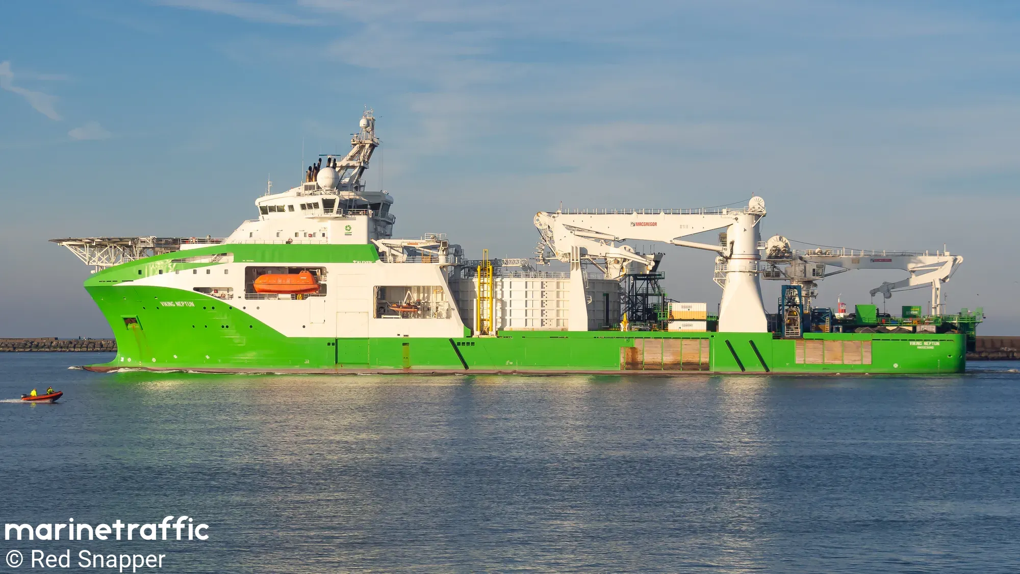
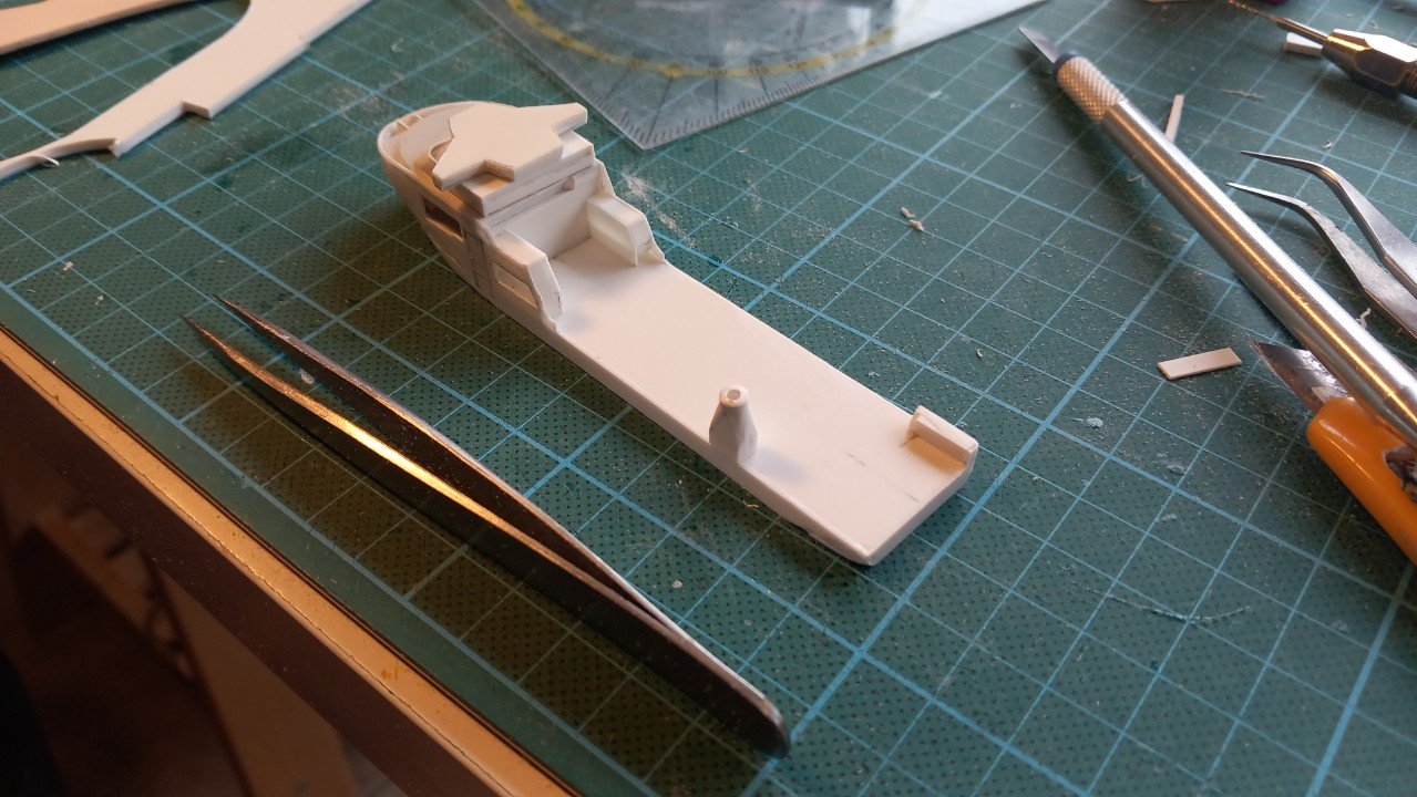
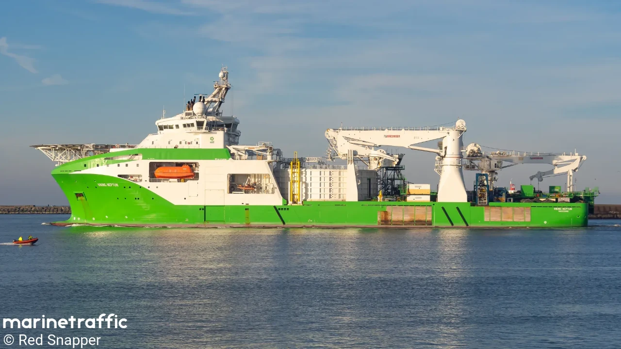
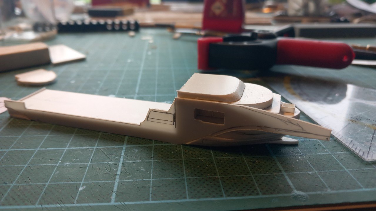
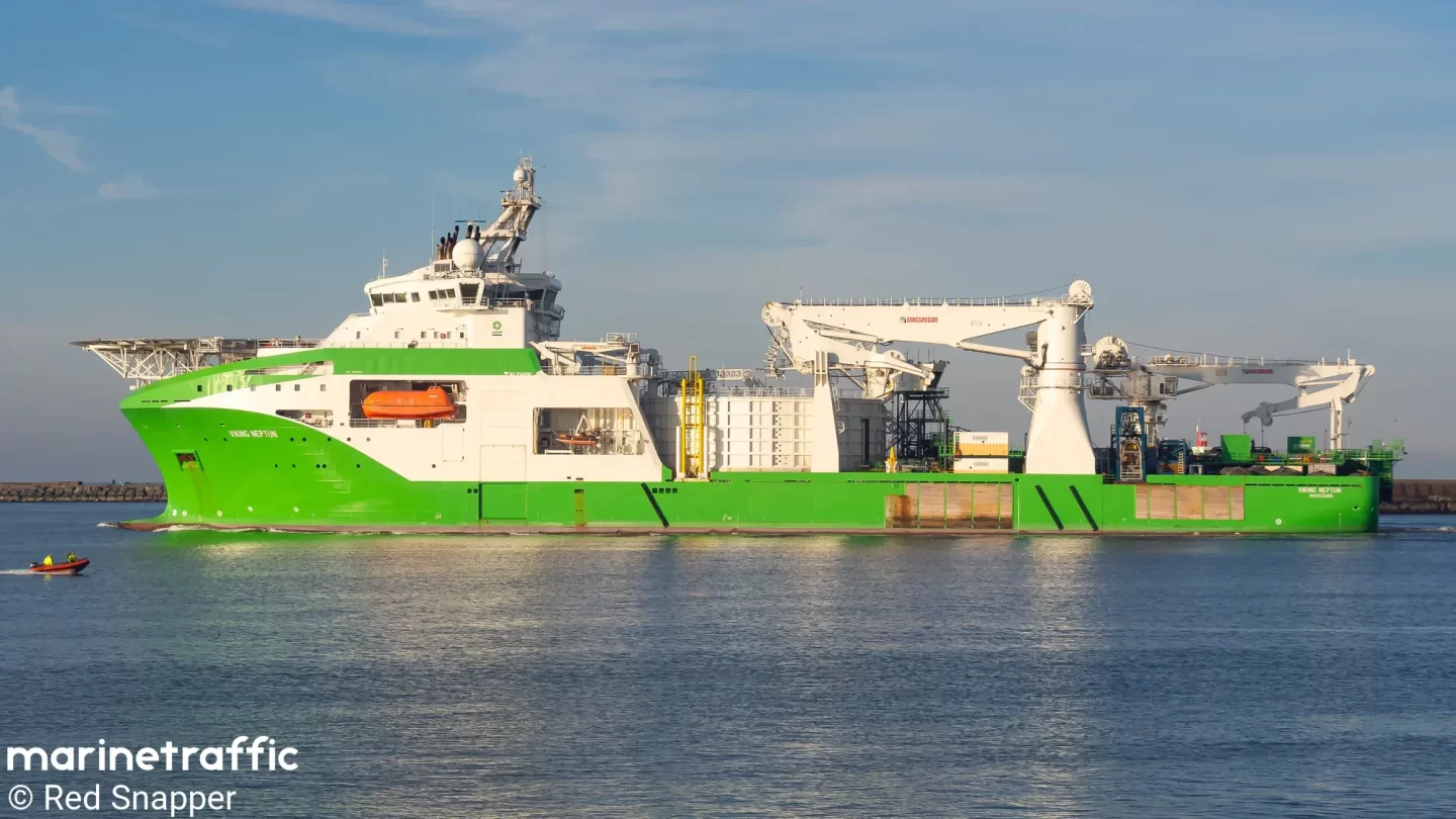
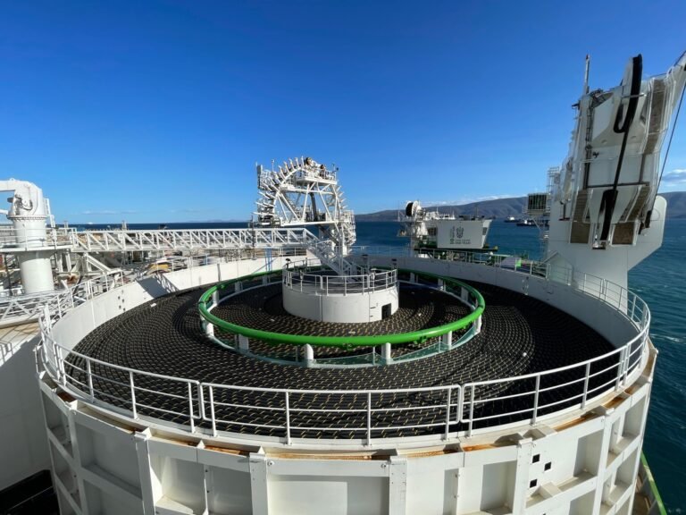
Thanks John, indeed speed is an advantage of this scale. Determining what to replicate and how much detail you'll put on it, is rather more difficult. A little more about the vessel and its operations. She's equipped with two moonpools, these are openings in the deck that go all the way through the hull to be able to work underwater with less exposure to the sea. One moonpool is the actual work moonpool to lower things to the bottom. The second, smaller moonpool is located below the aft part of the accommodation to lower an ROV. She has 2 ROVs (remotely operated vehicle), 1 is a Work ROV, the other is an observation/monitoring ROV. They can be either lowered over the side through doors or through that central ROV moonpool. As far as I know the moonpools are still there, but in the DEME version the moonpool is covered by the extra carousel on deck. Not sure if they are using the ROV system as I've seen the regular extra ROV A-frame aft of the big crane pedestal. Very similar to the Living Stone lay-out, so I assume there is a practical reason to that. Additionally, the original cable lay system was mounted on portside, just aft of the accomodation, so the ROV hangar and A-frame were close-by. In below picture you can see the original ROV door recessed between the lifeboat and rescue boat station. At the same time you see the blue ROV A-frame just behind the big crane pedestal. And today's progress. Continued adding some meat to the bridge level and mounted the first side shell. Decided to only put the large openings before mounting the shell to the hull. The small openings should be ok to cut afterwards, but would probably prove troublesome to cover for painting if I had cut them before. Also made a start on the crane pedestal. These are nice side projects when the glue is drying on hull or bridge parts.
-
Beautiful job. Large models always have that little bit "extra" effect compared to their small scale brethren.
-
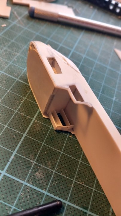
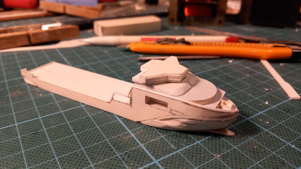
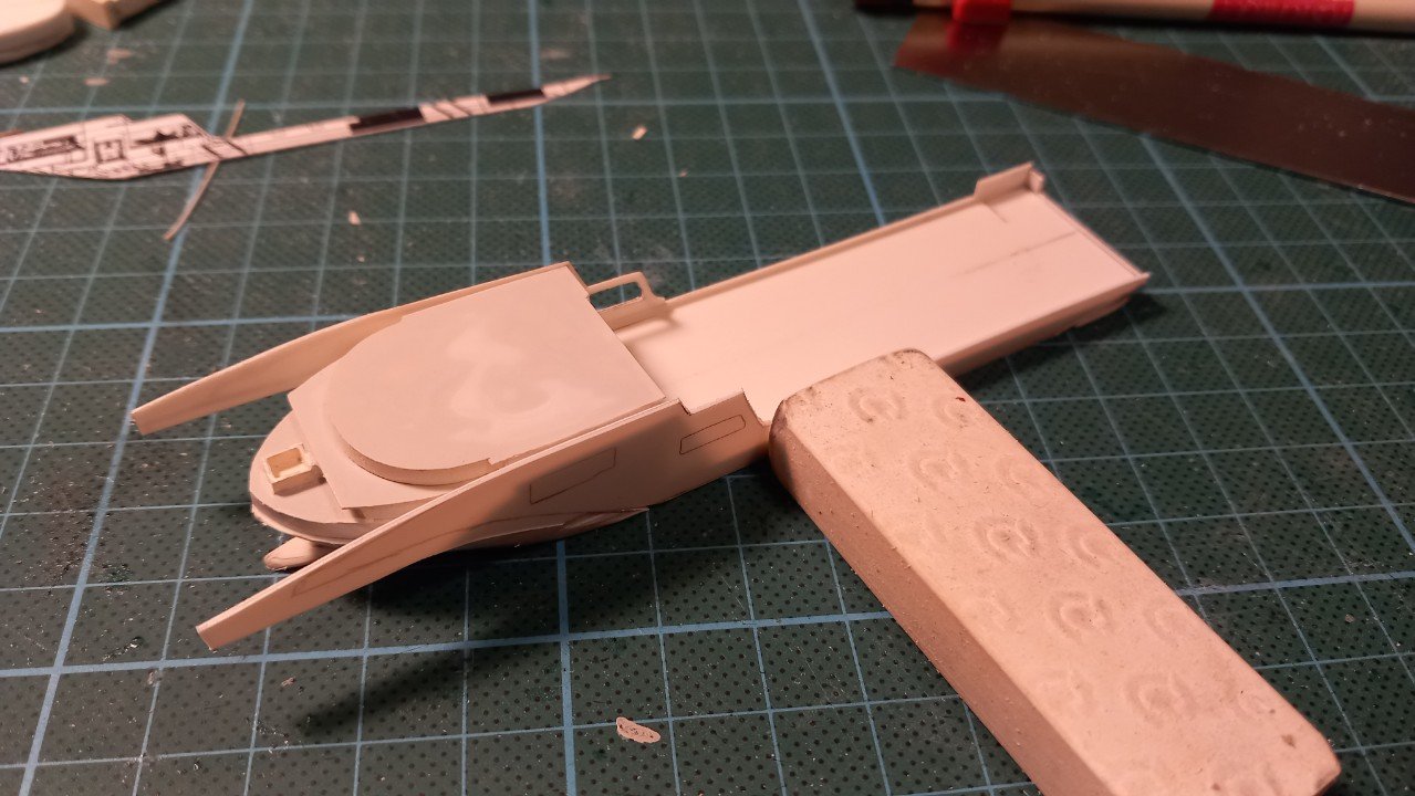
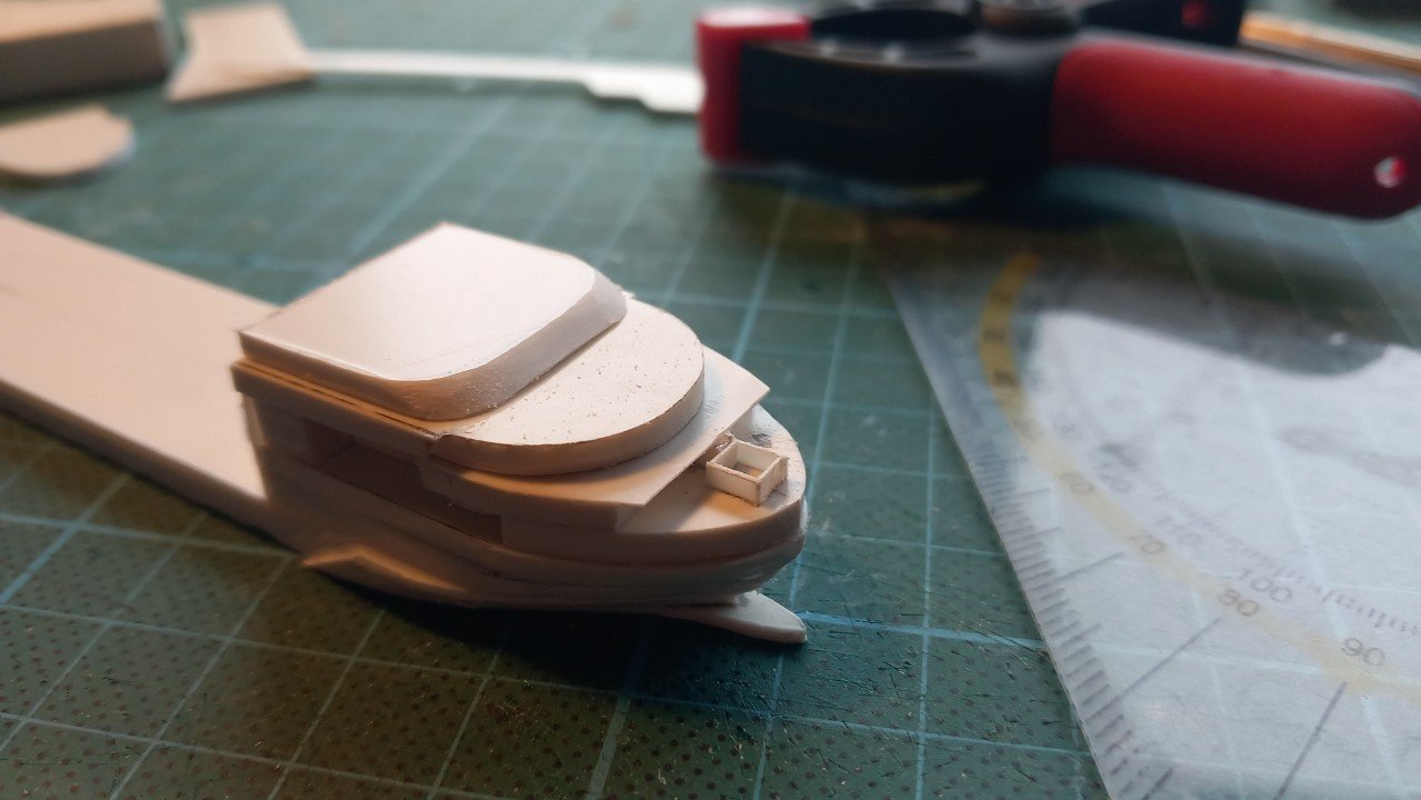
Plasticard 😄, so no, not really. It's styrene sheet. I do normally make paper and cardboard templates before shifting to styrene. In this case, due to its small size, I opted to go directly to styrene. I have 0.3mm available, which would give me sharper edges, but there are 2 issues with that. First one is that it melts excessively with the glue when used as a cover surface, this leaves bumps and pits in the surface. 0.5mm sheet retains its flatness. Second is more related to this build and that is simply the angled upper edge of the forward area. Some may not have noticed this, but the edge along the whole accommodation and along the aft edge down to the main deck is angled. The 0.5mm thickness allows me to recreate that angle by carving and filling along that edge. I currently started adding details and painting the some parts before I can place the sides. I'm also refining those sides, starting to cut the openings for lifeboat and rescue boat and carves that angled upper edge on the SB side. The fore deck has a swimming pool, which I built from 0.3mm styrene. All of that will mostly be covered by the helicopter deck though. What I love about this scale is that you can always continue building something. Even when you have a failure, due to its small size, it's easy to rebuild. In the meantime I have also built the first part of the bridge and large angled level below it. These parts really look like a starship and are a lot more complicated than expected. Every part seems interconnected rather than stacked and that bridge hardly has any straight surfaces.
-
Great work Bob. I'm following the build closely, but somehow I forgot to react each and every time! Love your colour scheme, I can't comment on the yellow vs ochre stripes, but I do know the yellow you picked looks really good on her. Good luck with the ratlines though...
- 261 replies
-
- 4
-
-
-
- Victory Models
- Pegasus
- (and 3 more)
-
Great colouring. Not sure on not putting boundaries forward and aft though. From the pictures it seems they had at least vertical beams with some regular planks to heighten the boundary. Seems some planks were missing, I believe they might have used it to guide overflow to a certain direction. That would perhaps also influence the weathering, since more material and dirt would be left behind in flow path. That is just an idea though.
- 457 replies
-
- 3
-
-
-
- sternwheeler
- Hard Coal Navy
- (and 1 more)
-
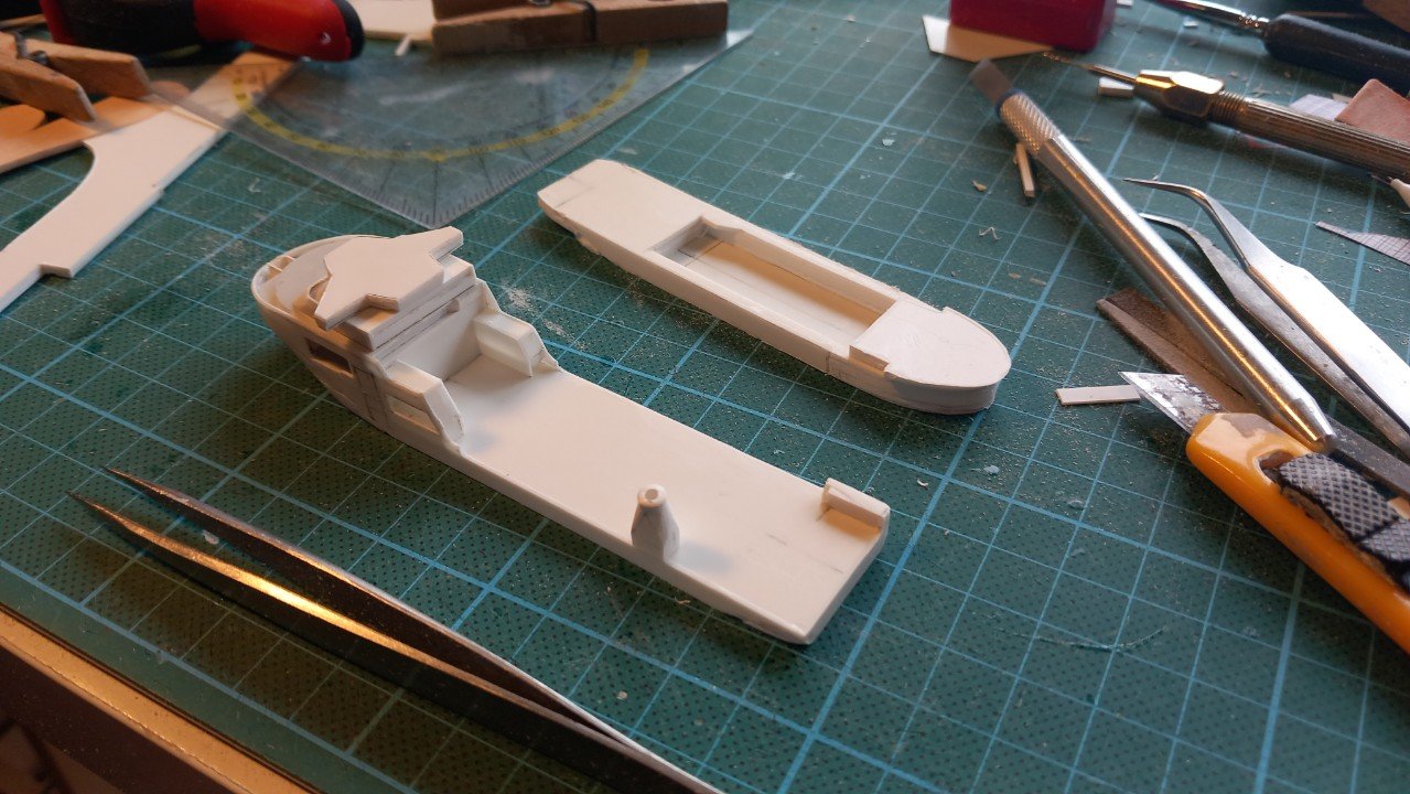
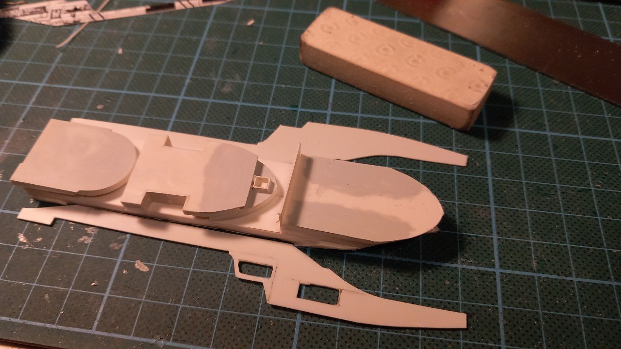
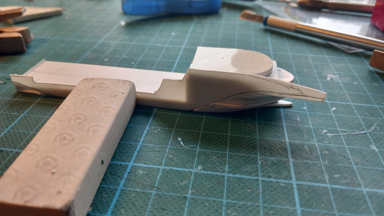
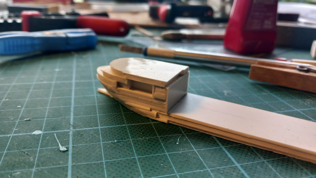
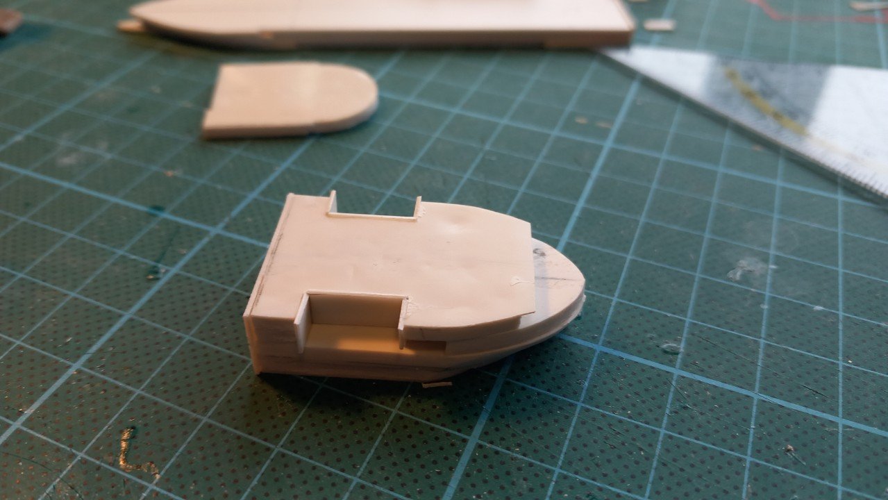
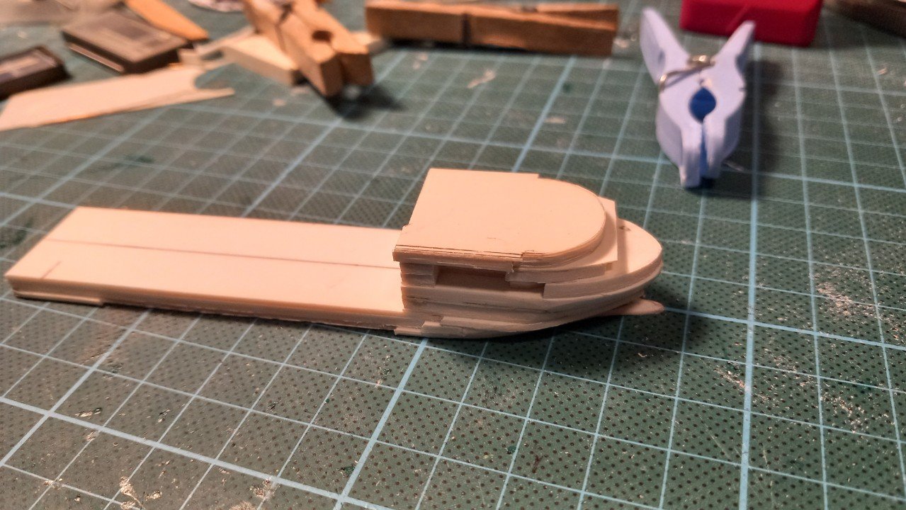
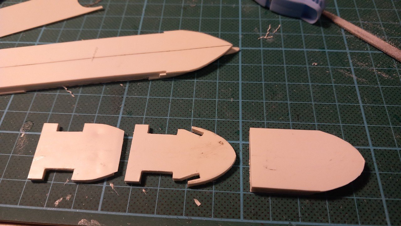
Welcome aboard each and everyone! Keith, you can ride that carousel, pretty sure it's slow enough for you to be safe, but still get excited. As a remark, I did not write an error in the ship's name. It really is Neptun and not Neptune. In the meanwhile I've been building. I have also started building the second vessel (named Lange Wapper), since I want to do a few actions, like applying putty, building lifeboats etc. in 1 go rather than sequential. So , construction will be a sandwich of different thicknesses. First a combination for each level, then a combination of different levels in blocks. Eventually I will wrap the whole thing in a 0.5mm outer shell, where all openings and portholes will be cut/drilled. The complexity of this build lays of course in determining where the openings will be and which part of the inner blocks will be visible through the outer hull holes. Blocks going together. For the largest openings, where the lifeboats will be located I opted for walls, to hide any seams in the stack. Those are then cut and filed flush with the surrounding surfaces. As you can see I have also mounted the aft bulkhead of the superstructure. This is only glued to the lower 2 levels. The upper levels are still dry fitted, since I need to detail those before the outer shell is placed. And a test version of the outer shell to show the concept. The sides of the stack are uneven and rough, those will of course be sanded flush before that outer shell goes on.
-
That planking job really is amazkng. Each time I see it, I'm mezmerized by its perfection. It would fit right in a manual or even a book from a museum. It's good to see you keep that same level of perfection in the bow details.
-
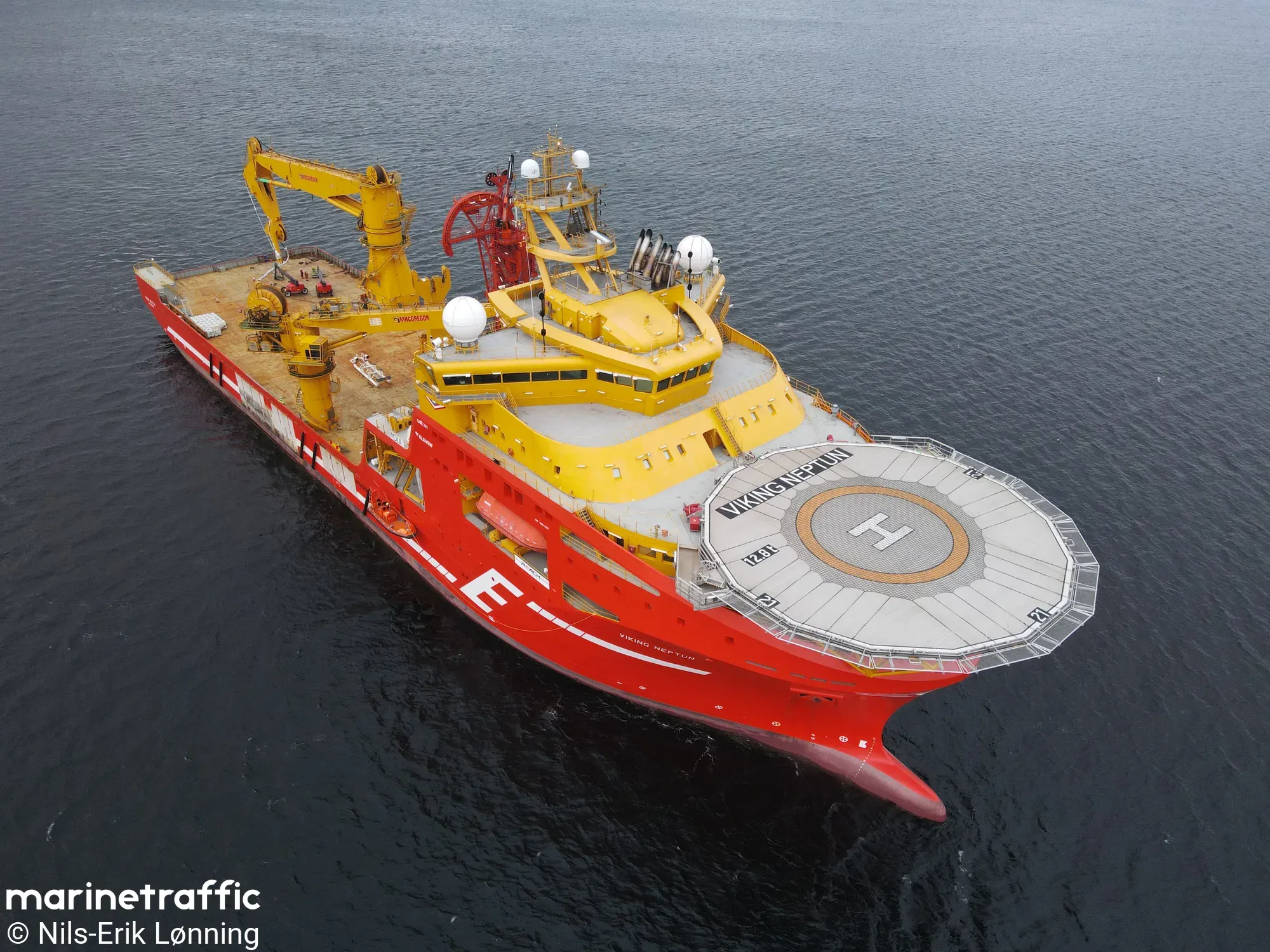
Well here we go. I got my first commission (sort of) for 2 small 1/1250 ships. Sort of, because I was planning to build those vessels in the future after all. I'm sort of lucky that the client requested a specific scale and simple waterline lay-out. Determining those is something that takes a lot of thinking and time in my case. 1 vessel is a slightly larger version (but a much older vessel) of Scheldt River, so nothing special there. So I won't make a build log for that one. The other one however is the Viking Neptun. A state-of-the-art Subsea Construction Vessel. She has (in my opinion) very sleek handsome lines, yet a strong purposeful appearance. Ya'll have to thank @Glen McGuire, for it, since he convinced me to start a build log. I believe it will be a challenge worthy of a log due its accomodation that is largely integrated into its hull/bow. It has proven to be a head ache during planning already. As is typical for these vessels, she has a Dynamic Positioning class 3 system. This means she can hold her position within certain weather boundaries with any defect. For class 3 that means that either an engine, thrusters or even electrical cabling can be disabled without her losing position. She started her life as a true SCV for the Norwegian Eidesvik company, installing manifolds in oilfields on the bottom of the sea/ocean. Additionally she is equipped with a cable carousel and an optional cable lay system for cable laying ops. She did those as well. About 1 year ago she was sold to marine dredging and infrastructure company DEME, to be used as a pure cable layer next to the DEME vessel Living Stone. She received an additional carousel on deck and a dual lane cable lay system, very much like the one from Living Stone. This cable lay system was built in smaller modules, so I assume it will be easy to remove in case subsea construction activities would be planned. For me the livery is quite difficult. I like the race-car red and yellow more than the yellow green-white livery. However, the client decided to go for the DEME version with full option, which means both the carousel and cable lay system on deck. You can put a lot of cable in there... She also still has her original carousel below deck, for a total of around 12000t of cable. That's it for now. I've started construction, so pics will follow soon.

-
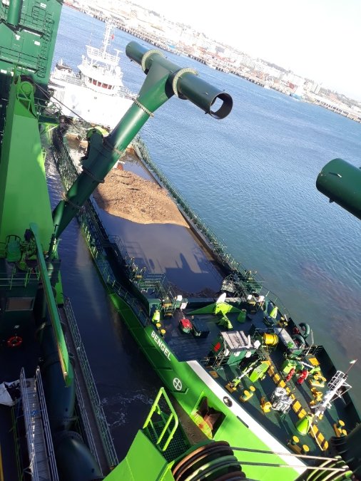
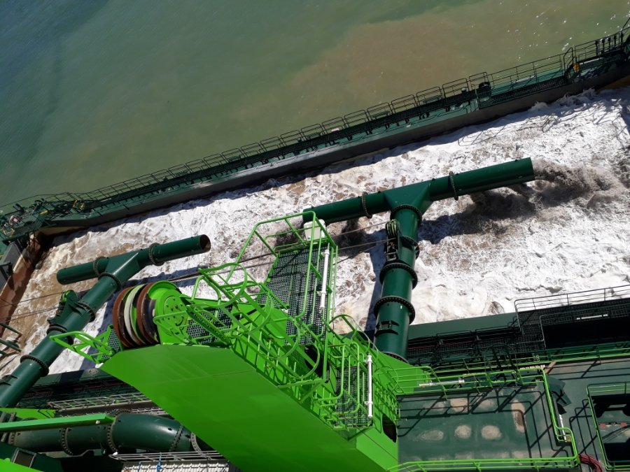
It does give an impact as Wefalck mentioned. There is quite a lot of turbidity, depending on the material you are dredging. Some examples below. If you look on the right, you can see the brown cloud around the barge. Mostly from the dredging itself, but a lot of it from the water overflow of the barge as well. And the condition of that barge has a sort of similarity to the dam. The heavy material sets down, while the water evacuates by an adjustable overflow. The water however is full of lighter sediment itself, flowing back to the environment. So practically it will also pass any dam when dredging nearby that dam. (In case of Keith's barge however, the flowrates and velocities were obviously lower). In this particular case the depth at which we dredged was reduced by 1 meter on a later survey. We did some testing and the sediment remained in suspension for up to 3 days. A period in which the life in that area is obviously disturbed. Turbidity is an issue nowadays. In some cases they don't even allow an overflow and basically make a barge transport a lot of water with a small amount of dredged material back to sea on each trip. Creating a huge waste of fuel to transport water to the sea, just to avoid turbidity. Dredging will always have an influence on life on the river-/seabed, there's no avoiding it, however, I believe humanity sort of agrees it's necessary. I do not judge, but saying it won't have an influence is certainly not correct. What scale this influence has, is up for discussion as the "original situation" is questionable (before or after the coal industry, before or after the construction of the dam and so on) That said, @Keith Black, if you need more examples of a barge filled with dredge material, let me know.
- 457 replies
-
- 4
-
-
-
- sternwheeler
- Hard Coal Navy
- (and 1 more)
-
Roel: Do you have a build log of this barge? Kurt To my own surprise it seems not. I thought it was one of my first shared builds, but it appears I've only put her in the gallery here: https://modelshipworld.com/gallery/album/2675-split-barge-bengel-1400/
- 457 replies
-
- 5
-
-

-
- sternwheeler
- Hard Coal Navy
- (and 1 more)
-
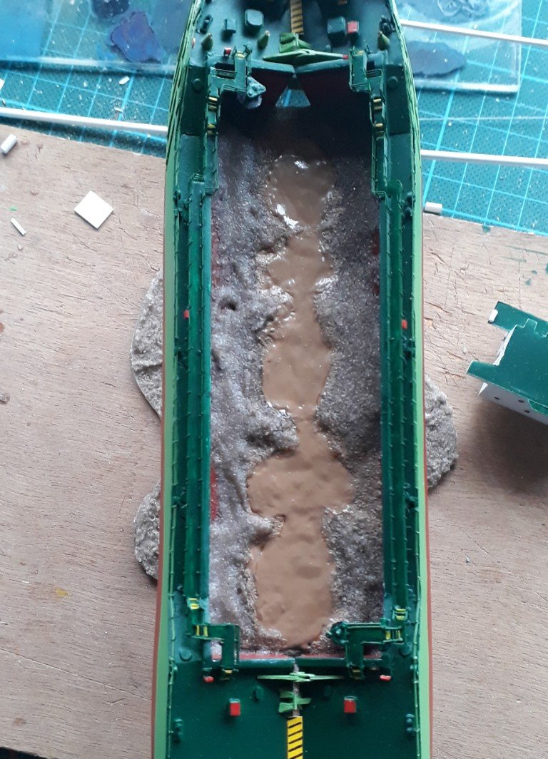
Hi Keith, This is the inside of my split barge Bengel. Might give you some inspiration. The rougher side dredge material is a mixture of acrylic gel with beach sand, the glossy wet look is caused by the glossy acrylic gel. You can add more or less sand for a rougher or smoother result. The watery inside is that same acrylic gel mixed with brown acrylic paint. You could add streaks anthracite paint in it as well.
- 457 replies
-
- 7
-
-
-
- sternwheeler
- Hard Coal Navy
- (and 1 more)
-
Late to the party, but definately enjoying it. Great job so far. Love the shade (and the result in general) of your deck. That close-up picture really looks realistic.
-
I think Keith's on to something here.... Other than that, glad you decided to put a penguin on your build, so where will you place it? 😁
- 156 replies
-
- 4
-
-

-
- Queen Annes Revenge
- bottle
- (and 1 more)
-
I'm in love with that room of yours. Love the arc near/around the windows and the colours you used. Very relaxing atmosphere. Apart from that, it's a brilliant looking model you're building. Looking forward for progress!
-
I'm using something similar too, however I don't use a pin vise. I use the directly with my fingers. Works great, most breakages is when I push them too hard into the plastic I'm drilling. I'm scared to put them into any machinery. Plastic rapidly melts and makes a mess of any drill bit when high drilling speeds are used. Don't know why you'd try dropping them from an inch high though? You have to rotate these things to make it work...
- 156 replies
-
- 3
-
-
-
- Queen Annes Revenge
- bottle
- (and 1 more)
-
The more I look at it, the more I'm thinking we're actually looking at 2 things, with the darker object looking like a davit/ handrail or pipe and simply a white looking object behind it... By the angle of the picture their edges seem to coincide, but perhaps they aren't just object. The forward pipe? seems glossy, it seems to have a lighter spot on the forward upper edge, which seems like a reflection... Just saying...🧐
- 457 replies
-
- 4
-
-
-
- sternwheeler
- Hard Coal Navy
- (and 1 more)