Javelin
-
Posts
632 -
Joined
-
Last visited
Content Type
Profiles
Forums
Gallery
Events
Everything posted by Javelin
-
 That is the bridge itself, however in your defence it's complicated on this vessel since they've incorporated the funnel into it. I believe this is done for several reasons, perhaps even to use the heat from the exhausts to heat up the accomodation She's built for cold weather and effeciency after all. That bridge is built from styrene, several layers, thickness adapted to certain steps required by its shape. I cut those layers in the shape of the largest dimensions (roof top), then I draw the bottom outline on the lower surface and then I carve and/or file the sides connecting the top and bottom outlines. Hope that is somewhat clear?
 -
Small structure? 🤔 Assuming you're asking about the base of the mast, everything is styrene. The bridge as well actually. The only parts that are just copper are the stanchions (made from electrical wiring, rolled straight between the tabletop and a steel ruler). Also the exhaust pipes, which are difficult to see in these pics, are also brass and copper wire. The windows are done with a very fine tip marker. Sometimes I use 1 or 2 rows of masking tape to keep them in line on the bottom and/or top.
-
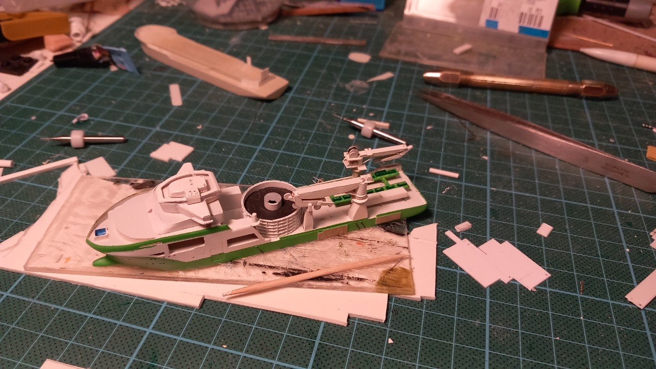
Moved ahead on that mast and started adding windows all over the place, to be able to move ahead on the final phase. I've been producing a lot of details as well, so I'm nearly finished with those. Only the ROV and its A-frame are remaining. The helo deck is also in its last phase by now, adding its darker coat and putting at least H with circle on it.


-
Thanks, moving forward. Finished that darker grey deck colour and continued with the helo deck and its supports. In the meanwhile also started the challenge of that fancy mast structure. Doesn't look too good for now, but next attempt will be better. It's mostly the middle platform that causes issues. (still a template for now) And the cable lay system is advancing as well. I will be able to start installing a lot of parts now since the grey paint is on.


-
Thanks for the reactions everyone. I've now come into a detailing phase, lots of work and little to show for it. Prepared a lot of items for primer and final white coats. Cranes are nearly finished, the control cabins are also sprayed, but I still need to add the windows before mounting them on the cranes. They will also get fly tying thread wires. As you can see, the cable lay installation is started. A lot items are left out. below you see the stern chutes (shoots?) in progress. They are probably the most fiddly parts I ever built. Mostly built up of 0.3mm styrene sheet and just 1 single straight edge on the whole thing.... In between I'm doing some "quick" items like davits and the large yellow boarding ladder (called a "surfer" to transfer people from small craft at sea). On other ships its either near the stern (bad when the vessel is pitching) or permenantly on the side (annoying when mooring since it requires decent fenders and often interferes with shore fenders). So here they seem to only hang it over the side when they use it. The helicopter deck is also cut and primed. The reason it's all still dry fitted is that I'll need to repaint the deck in a slightly darker shade of grey (as well as the bridge top, chutes etc.)
-
Kan nog 5000 duimkes bijzetten, maar je hebt het wel begrepen denk ik. Love it. So small, yet colourful. Those leeboards indeed look very heavy for their hinges, yet on the other side they are made of wood, so their weight itself would mostly be carried by the water when deployed. In operation I also don't believe the righting forces would be that large considering the limited size of the vessel.
- 97 replies
-
- 1
-

-
- Corel
- Große Jacht
- (and 2 more)
-
That's funny,I was really just thinking about you and this build yesterday. I was just about to request for an update or check if I'd missed something in your log.... And here you are! Happy to see this update, although I don't envy you for that sanding work with the stick!
-
Well I have to admit the knife in question is around 3 years old... And I have to admit, or announce that I have a Vanguard HMS Sherbourne on the way! I finally took the plunge. Joined a couple of years back to start building wooden classic vessels, but had trouble to get started. Very difficult to decide between my normal habit of scratchbuilding or starting with a kit. So recently I figured I just needed to take a step and see where it goes. As for VN, this where we were yesterday. It still needs some fixes, but overall it's quite ok. Of course I also still need to paint the black tube fenders and wooden (grey-ish) landing areas.
-
Hi Phil, I believe John is talking about the device next to the pelorus inboard of the cap rail. I assume there is a voice pipe to the engine room with a brass cap and perhaps a sort of telegraph with brass rotating angle?
- 480 replies
-
- 2
-

-
- minesweeper
- Cape
- (and 1 more)
-
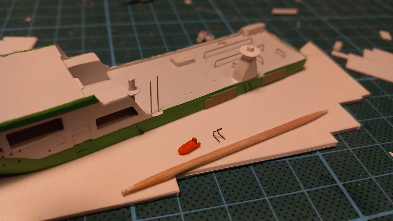
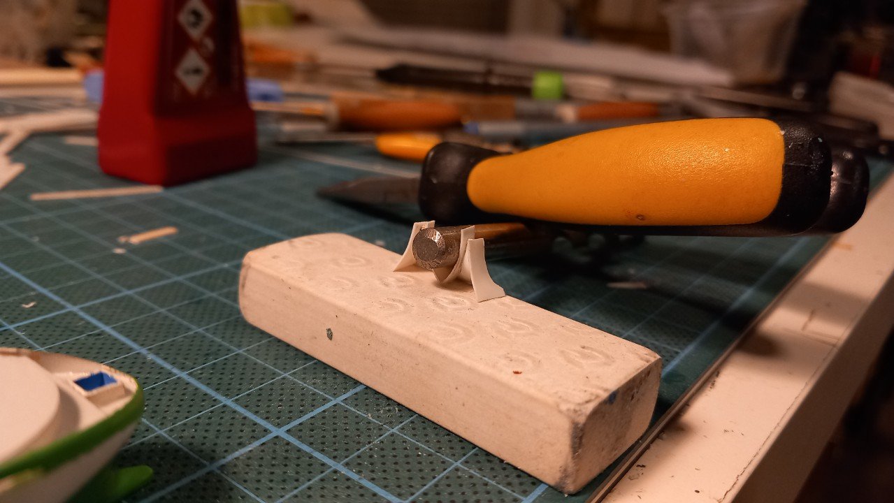
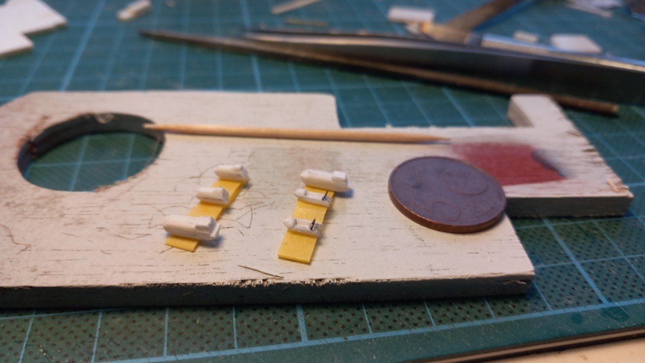
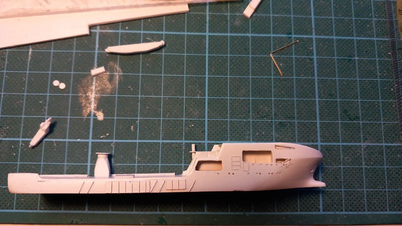
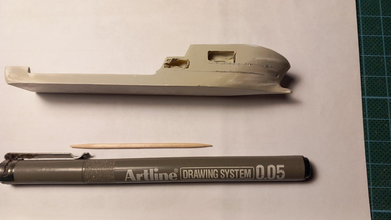
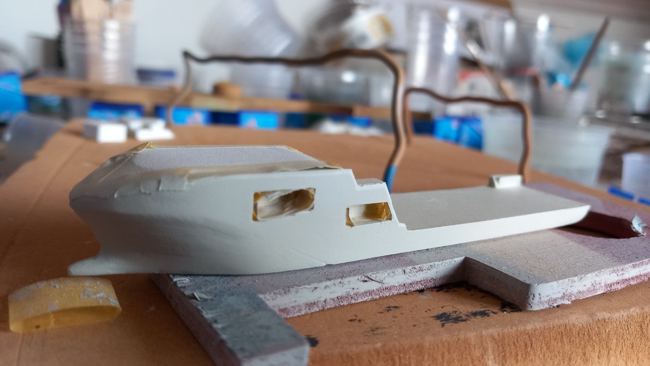
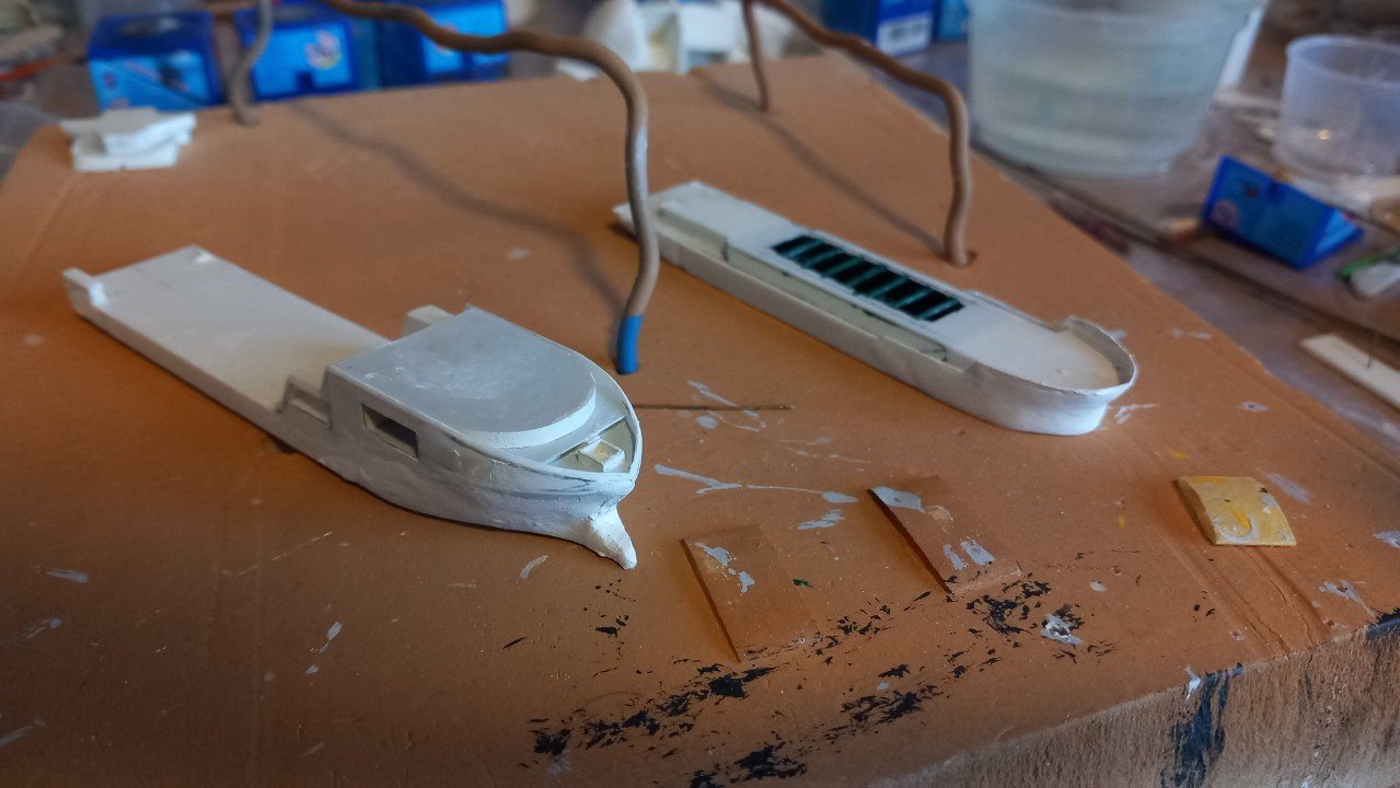
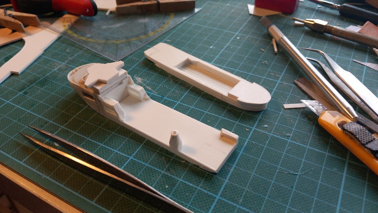
I was referring to Tonnes. These vessels can lay different cables, there are inter-array cables that connect wind mills with each other and to the transformer station (also located in the wind field) and there are export cables, which connect the transformer station to the shore network. Inter array cables are shorter in length and relatively small diameter, while export cables are several km long and large diameter. A third type are cables that connect countries, like UK and France, or islands. Due to the different diameter and weights of these cables, you can't define load capacity by length of cable, but only by the load limit by weight of the vessel. It looked quite ok to cut the small openings in the hull, but I guess lack of patience got the better of me... The parts where I needed to cut were unsupported 0.5mm styrene and noticed small cracks in the paint when I started putting some force on the knife. I also drilled the corners, as usually, as this prevents propagation of a cut and allows an angle on the knife. The cracks in the paint were acceptable, but on one hole, disaster struck... I assume the styrene may have been weakened by the sanding, and my knife wasn't the sharpest in the pile. In any case, the forward edge gave way and a piece broke out. The other side was acceptable. Time for a repair. It's not very elegant, but least I learned a couple of lessons again. Difficult to put in the filler as there was nothing to support it. Luckily I thought about removing that tooth pick in time because it was almost stuck to that filler. Time to redrill the portholes and sand the repair smooth. And then careful cutting with a sharpened knife. In the meanwhile I also continued the main crane and prepared the lifeboats and rescue boats for VN and Lange Wapper. Notice the difference in VN's lifeboats and Lange Wapper's. Offshore vessels often have a crew (and many visitors, representatives etc.) of 70 to 100 people, while dredging vessels are often limited to 15-30 people. I believe I will have to give the vessel another coat of white to fix the tiny cracks and cover the repair (although most of it would actually end up yellow-green).
-
Ok, you 2 got my attention... Indeed interesting as I have 2 similar ships (Rambiz and Gulliver) on my radar, bit I'm scared of any PE as I had some bad experience with that. For SIB's I'm quite sure some use PE on their builds considering the leap in sharpness between their builds and more regular builds. I'm however quite scared of squeezing any PE mast or crane when mounting it in the bottle. And for your interest, there is a whole museum in Germany: https://www.modellmarine.de/index.php/fotogalerien/178-/7671-buddelschiffmuseum-in-ditzum-2025 That said, back to topic. I'll be following this one with great intrest, that locomotive really needs to be part of this build as well!
-
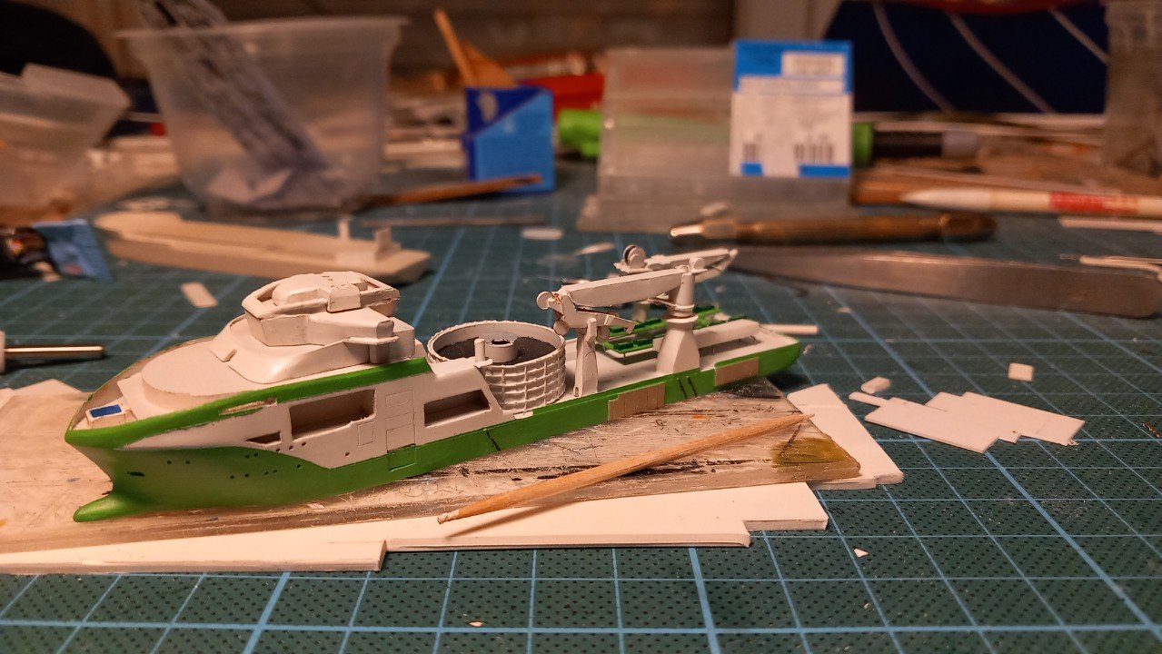
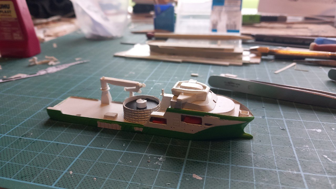
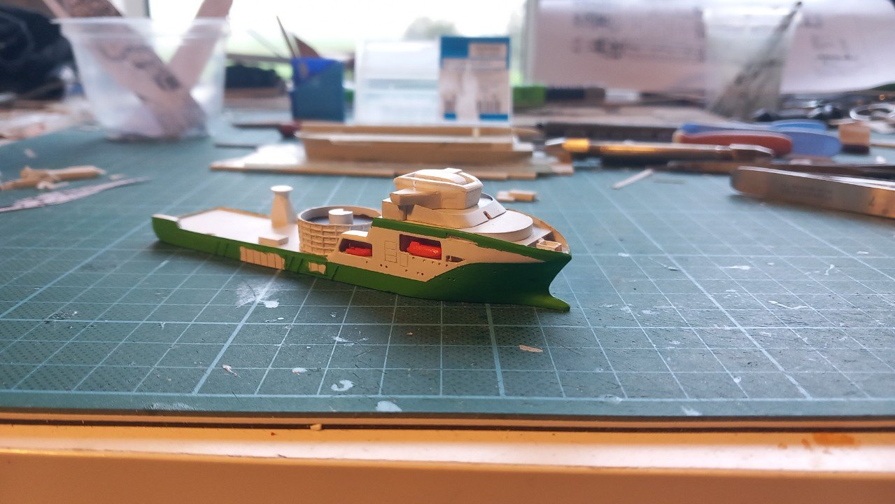
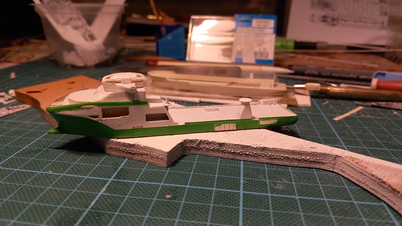
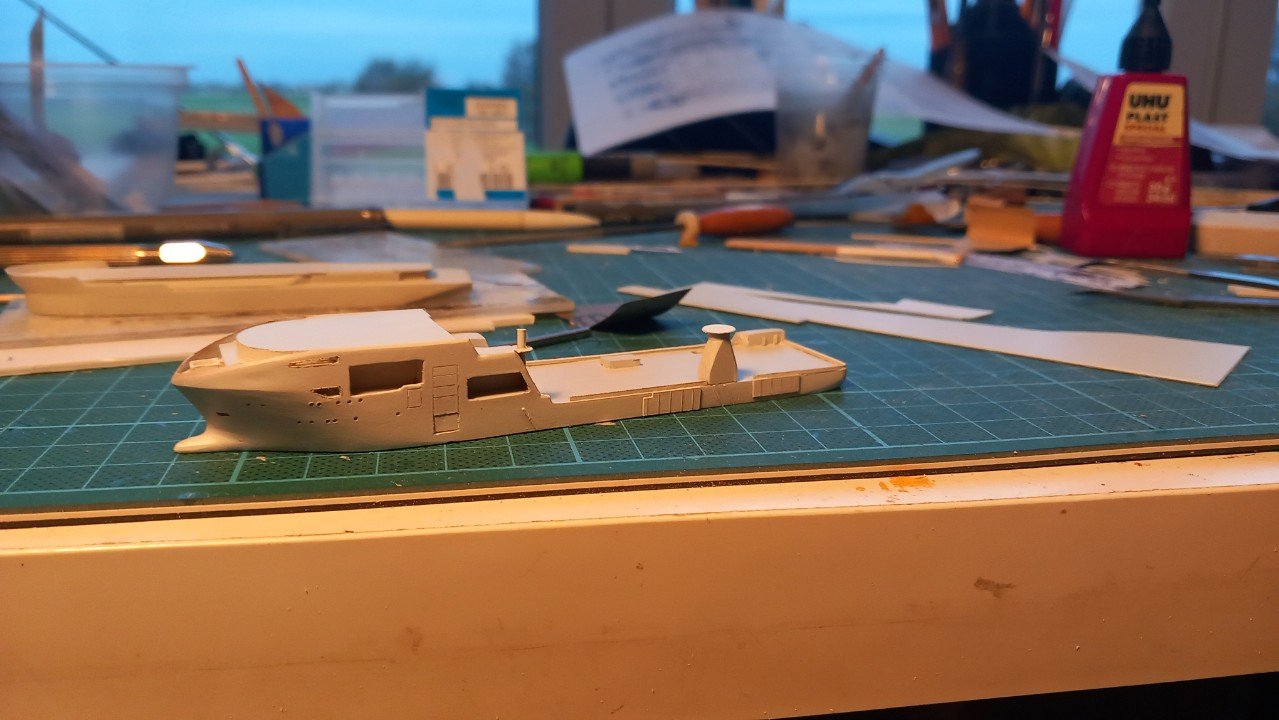
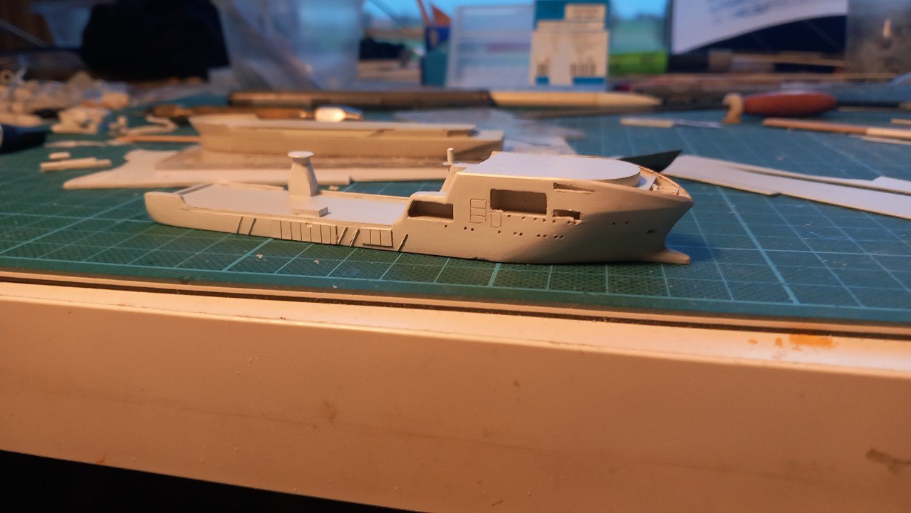
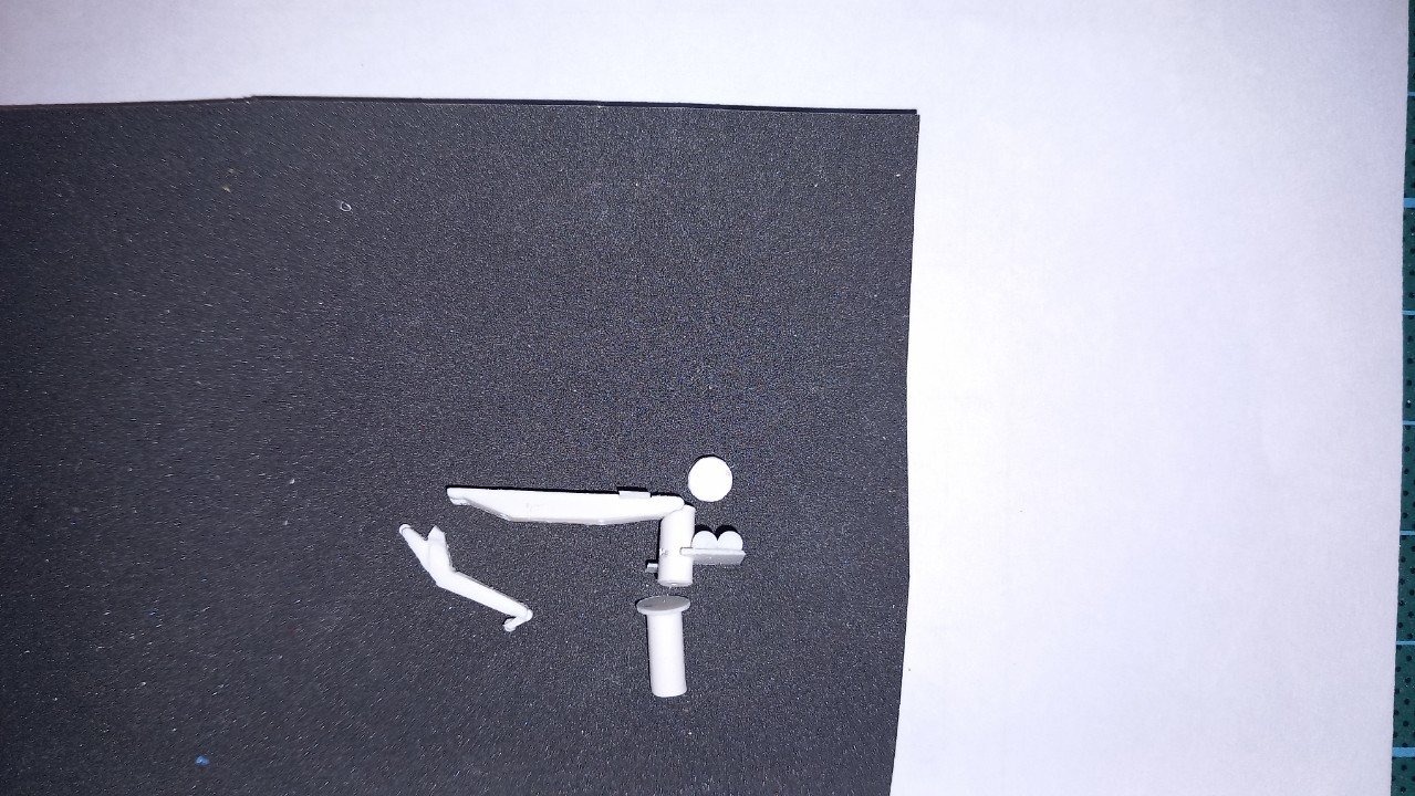
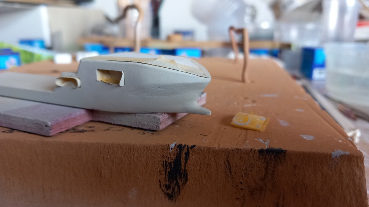
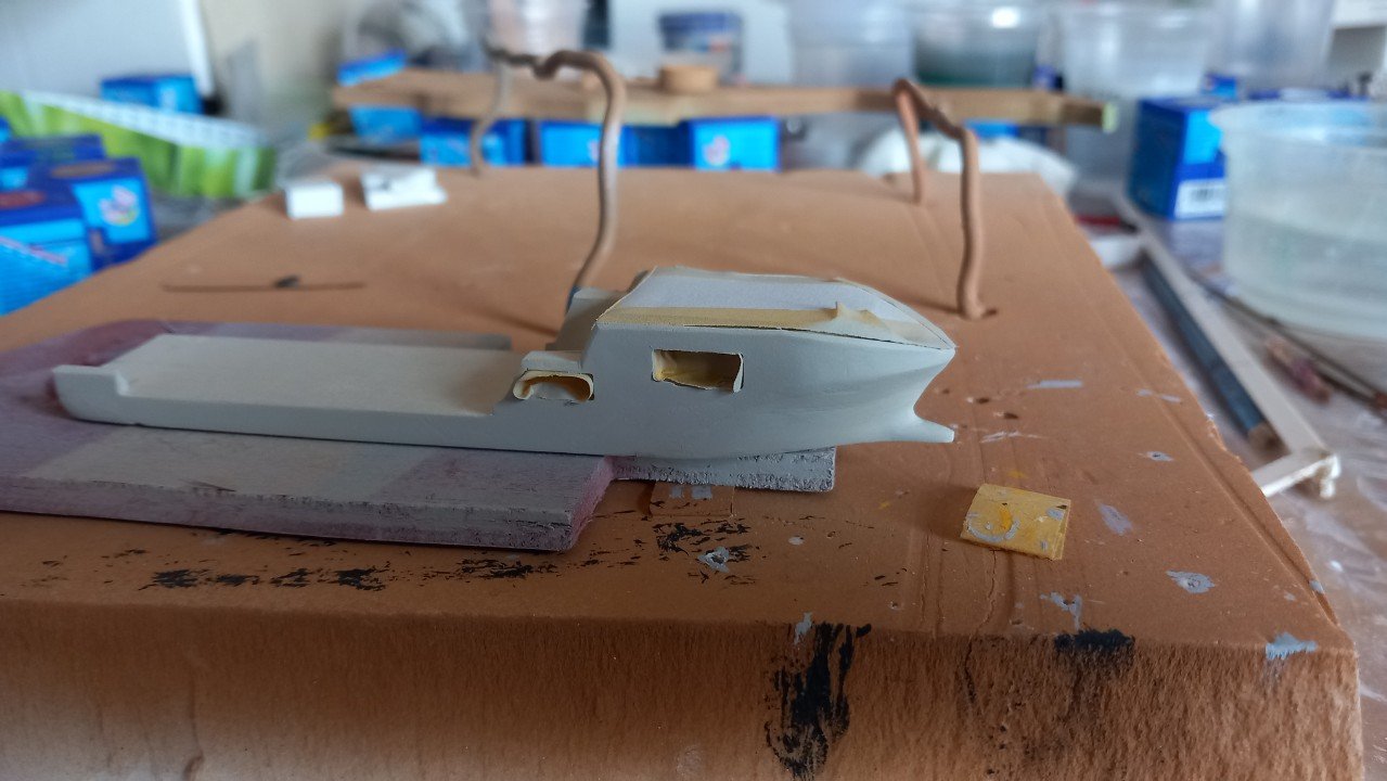
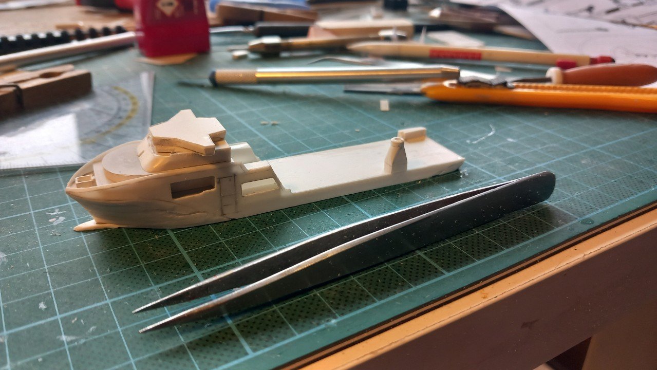
Today a rather big step forward. She, along with some parts, received her coat of primer and final coat of white, for the white parts that is. I'll let it dry thoroughly before masking the white and putting the yellow-green. Additionally, I finished the lifeboats, but I'm waiting to paint them until I finish the ones from Lange Wapper and the 2 rescue boats from VN. As you can see, I've also continued on that complicated and fancy looking bridge top.


-
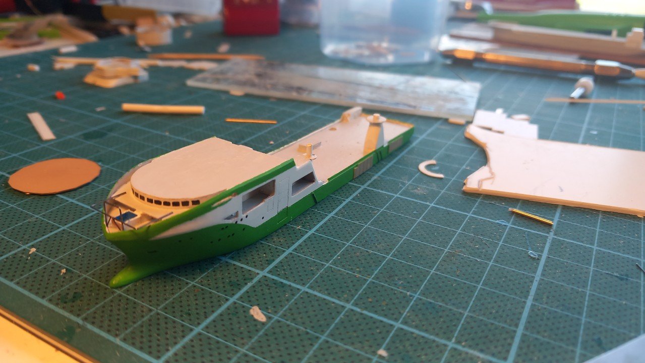
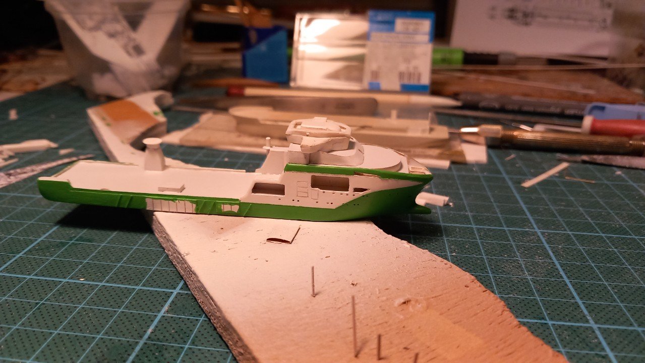
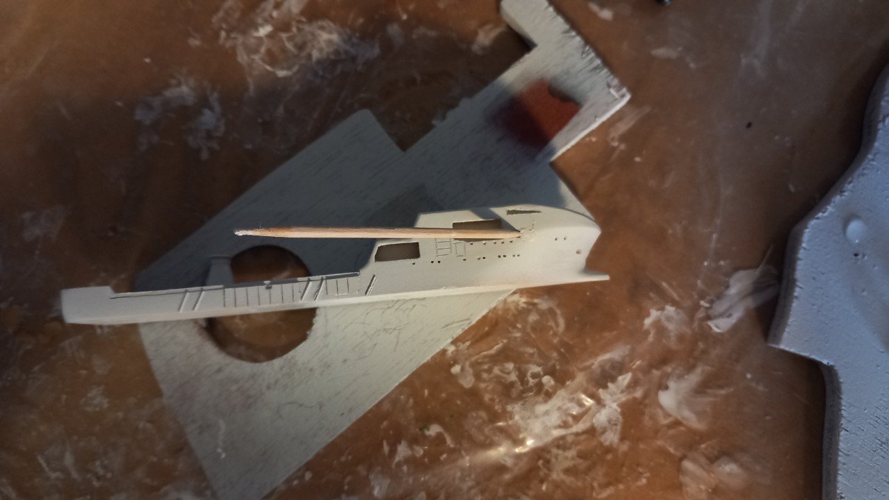
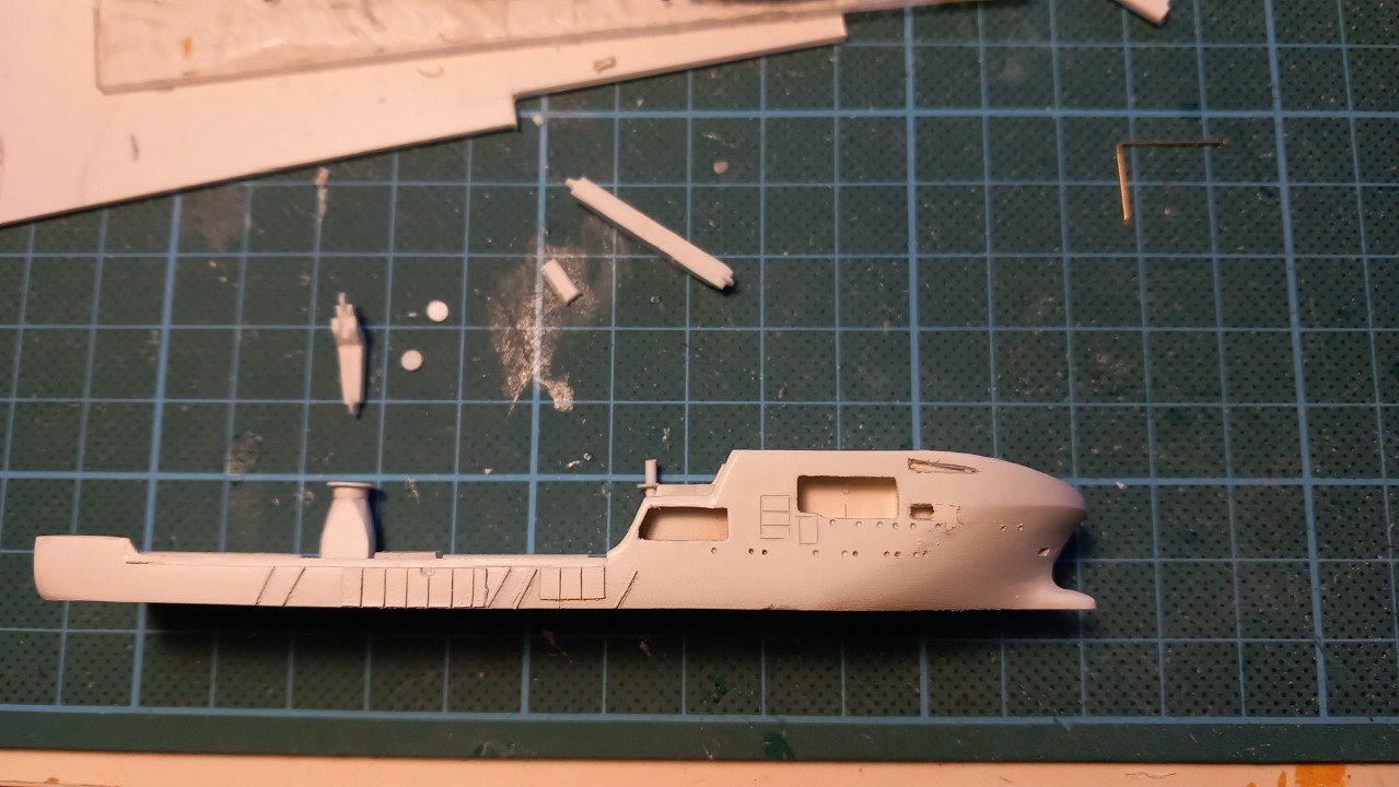
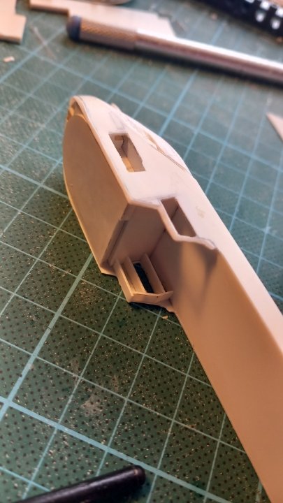
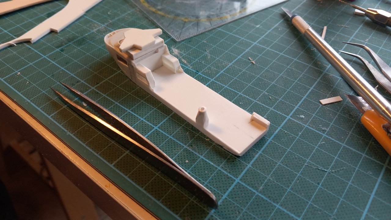
Short update this time. Tricky detail on the portside is a partly recessed piece, where the panel of the ROV slides down when the A frame is deployed. I had foreseen this, but didn't want to cut it out before mounting the sides in case it wouldn't be perfectly in the right spot. So I decided to carve it out now, removing a piece of 0.5mm, and replacing a small 0.3mm panel inside the hole. This way I got a 0.2mm recess, which is about right at this scale. I also scribed some panel lines and the areas that are to be removed after the white paint is applied. Decided to add more detail, including those fenders, wooden landing areas and bulwarks on the aft. Crane pedestal is fused into the bulwarks, so that one is being placed before primer as well. I'll put this one in primer and prepare the Lange Wapper for primer while VN dries.

-
You know I had my reservations about that base, but looking at the forward side of it, and with the wooden cupboard/table underneath I really love it! The mod podge-beach idea really looks nice as well. So comes the eternal question: How are you going to make anything more impressive?
- 156 replies
-
- 4
-
-
-
- Queen Annes Revenge
- bottle
- (and 1 more)
-
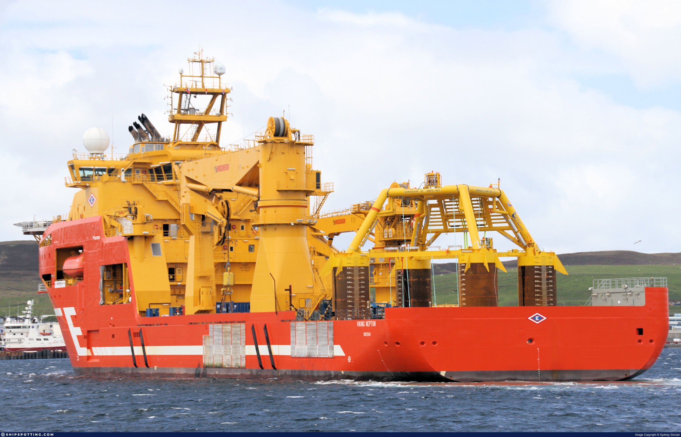
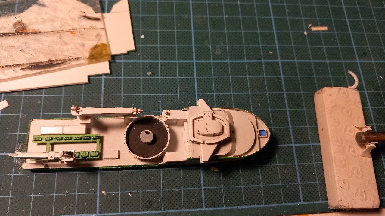
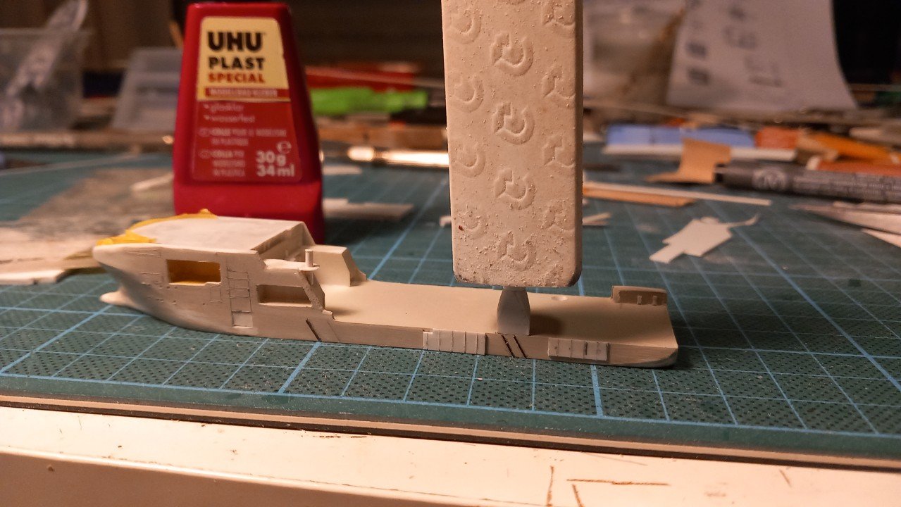
Here is a picture in her old SCV role with a "typical" load, a piece of oil exploration equipment, on deck. This is one of many structures that are placed on the seabed inside an oil field. Since we seem to be recommending movies around here nowadays, in this case the 2024 movie "Last Breath", featuring Woody Harrelson is worth watching. Not strictly subsea construction related, but gives a good idea of how important that Dynamic Positioning is and also some background on everything that's going on on the seabed. On to the model. The carousel got its primer. The vessels had additional putty and spray putty applied. On Viking Neptun, I now sanded her with fine grit sanding paper, cut out the recesses for the anchors and started drilling portholes. Will probably continue detailing the sides, scribing lines etc. before continuing to primer, then white and finally the yellow-green. Haven't determined yet if I'll add the wooden landing areas and rubber bar fenders on the side of the vessel before spraying the primer or after... During drying of both vessels, I also proceeded on the auxiliary crane. I believe her main hoist is 100T SWL, also with a wire length of 3000m. It also has a lighter auxiliary hoist. The main hoist does have its wire on a big drum on the back of the crane itself. In different pictures of the real vessel you will see the crane jib rests and even the auxiliary crane itself, are being moved around on deck. This is done during preparation of projects (called mobilisations) and adds to the cost of such offshore projects.

-
1) I agree, might be water running down, but not entirely sure where from/to 2) I believe that is actually one of the paddles of the wheel coming up, but dark due to the lighting/ shadow 3) hadn't noticed that detail.... seems a bit exposed for an oil pipe, but then in those days.... 4) 🤣
-
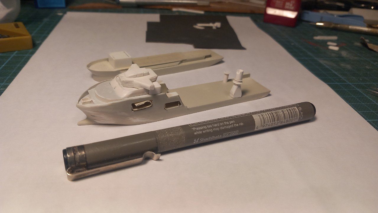
Took these before your request, but I will put something in front in the future. She's not that small, since the real ship is quite large (about 50% longer) than Scheldt River. Also the Lange Wapper is a larger hopper dredger. In any case, first sacrificial coat of spray primer is applied to both vessels now. I also continued a bit on the main crane. The main crane is designed for subsea construction. She's a knuckle boom crane with a 400T wotk load. She has a main wire of 126mm diameter, which is really big. I'm used to work with 86mm wires and those weigh 30kg per meter of length, I'm curious what this 126mm version weighs. Since she needs to reach the bottom of a large part of the ocean with it, the wire has a length of 3000m (3km)! It is therefore stored under deck on a huge winch and passes through the pedestal up. The smaller drum at the top of the pedestal is the auxiliary wire with "only" 100T Safe Work Load (SWL). As you can see on the above shots, she will require a little more sanding and puttying.
-
Not entirely sure on those springboards, I actually believe these beams were holding her off the shore. I mean ropes are making sure you don't go off a quay, but what is keeping her away from shore when there is no quay? She'd run aground if the wind came from the sea side... I believe that door on Billy might have been used when she was alongside the quay or sailing without the barge. Having the door open and have a gangway/plank straight into the door opening. Luckily you mention it's a sternwheeler as I keep thinking those wheels are at the bow... I believe it's due to the funnels being forward of the wheel house. Looking at that last picture, it looks like the real exhaust is sticking out between the wheels (lighter vertical object), with the planks around it blackened by soot (blurry darker area), so your assumption that the engine could be between the wheels is probably right. Or am I seeing things here?
-
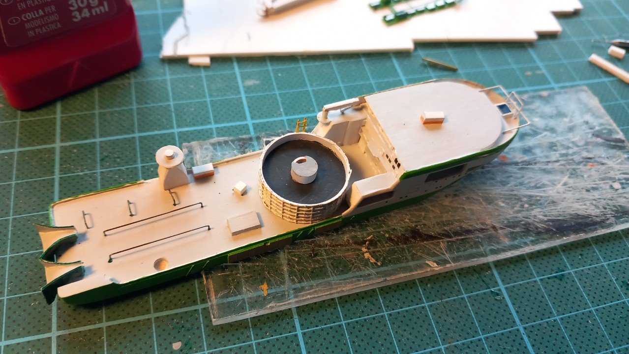
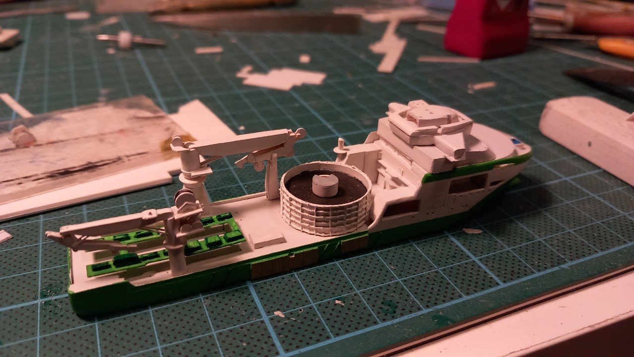
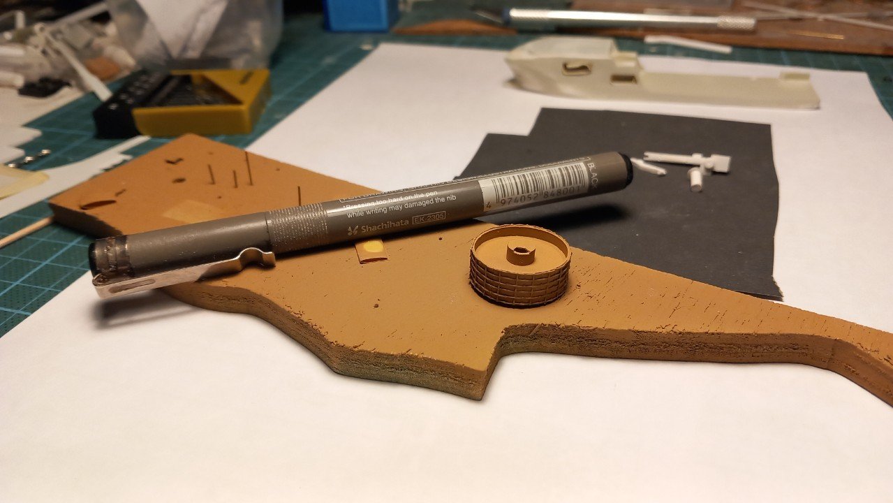
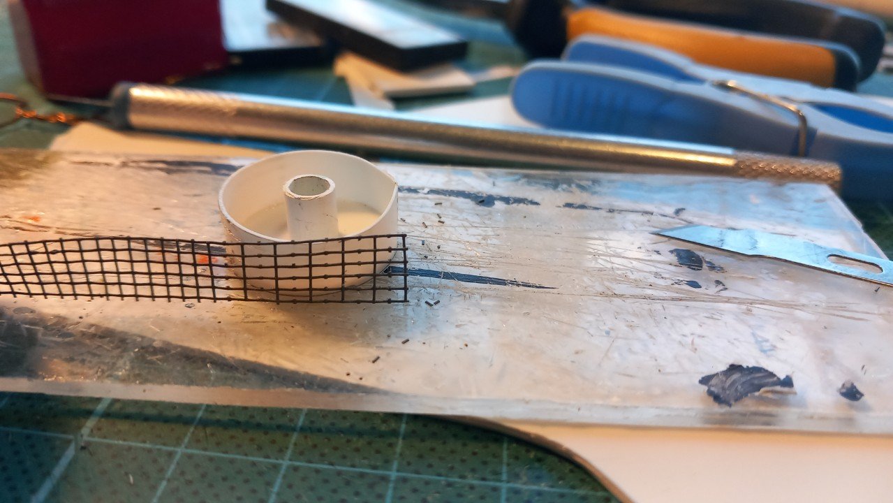
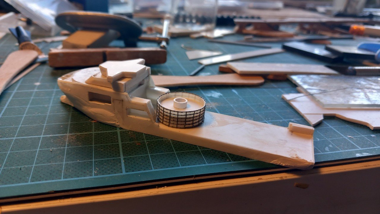
So, finally got to the stage of putting epoxy putty on them. Now on to some hours of sanding and probably filling some smaller pits. In the meanwhile I started work on the carousel. First tried to get the proper dimension by turning a piece of PVC pipe I had laying around, but the dimensions were still just too large and thick, so I eventually built it up from a disc with 0.3mm side shell. As you can see, it's not perfectly round (slightly pointy on the right), so I decided to make it look as if it is partially filled with cable. Put some filler bars on the bottom and then forced in another disc, somewhere midway. By gluing the shell to that disc, it did become nice and cylindrical. I then tried to put copper wires to get the horizontal stiffeners. However, the amount of vertical stiffeners was goint to cost a lot of time... So, since laziness is the mother of invention, I went to check some fly screen netting. It seemed quite right, thickness not too much, vertical spacing perfect. All I needed to do was cut out every other vertical stanchion. It's not perfect, but better than a bland looking wall. It'll all be painted white after all. Both vessels will now be sanded and continued until I can apply some spray filler/primer. Then their paths will diverge again.
-
From someone who made the same mistakes (see topic on LPG tanker Chaconia), I can give you one advice. Either start over on that hull starting from the beginning and make those frames again, but perfect this time. Or, less optimal, carry on, the way you are going now, but continue with filling and sanding untill it truly is perfect. Use primer layers to spot the bumps and dents. I do fear the wobly hull will always show through though. Filler can only do so much. The reason I'm saying this, is that such ships are a long process and your skills evolve during construction. In the end you're building good details etc, but still on a less-than-perfect hull, and it's going to bother you, believe me 🙄. That said, at least you took on a rare scratchbuild project and got started (that's better than 99.9% of people). If you finish it, people will certainly admire it, unable to understand how you pulled it off.
-
Beautiful work Phil, these different colored details really stand out and make the real difference between a good model and an excellent model!
- 480 replies
-
- 2
-
-
- minesweeper
- Cape
- (and 1 more)
-
Not talking about booms for lowering the boats, but booms for entering them. Like ones seen on HMS Formidable here: HMS Formidable Sailors would crawl along the boom to the ladders length towards ladders, the boats would be moored side by side along the boom below the ladders. As mentioned I'm not entirely sure. You also see the boom on Formidable is mounted on the hull side rather than on deck. But I don't think it's impossible.
-
Given their position in relation to the boats's position, I'd also say they are the booms to moor and embark the boats. They also seem to be long enough to serve that purpose. Regarding rigging to deploy and stow them, no idea. Perhaps connected near the upper stowage support?
-
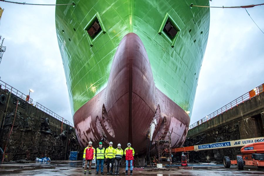
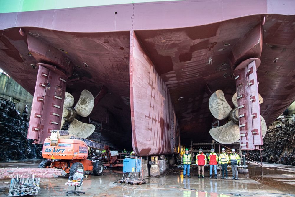
Thanks Paul. A litte more about that real ship. This is not relevant for this build, since this is a waterline model. (perhaps for a future racecar red version?). What makes her somewhat special for a modern offshore DYnamic Positioning vessel is her rather conventional propulsion. Where most vessels in these classes are relying purely on azipods/twin pods etc. Basically propellors that can be turned 360°, Viking Neptun has a conventional twin propellor-twin rudder propulsion. In addition, she has 2 regular bow thrusters, 3 stern thrusters and just behind the bow thrusters, 2 retractable azipod thrusters. That's a lot of power and thrusters to hold position and heading. You don't want to tangle lines 2km below the waterline... As mentioned, a lot of them are simply redundant, so that in case of failure of one thruster, or a complete power production unit, she can still maintain that position and heading. As a disadvantage, this means all engines and thrusters need to run during DP operation, which means the engines are continuously running at very low power, which they really don't like. In above picture you can see the rudders are of the Becker type, which means there is an additional piece that hinges in the same direction as the rudder, this doubles the effect of the rudder, so a 10° rudder angle on this type of rudder equals a 20° angle on a normal rudder. They can also often be used at greater angles, creating a nearly 90° deflection. The propellers are variable pitch propellors, the blades can rotate hydraulically, to change the thrust while keeping the same rpm. This means they are less efficient (compared to fixed pitch) for pure sailing, but makes the vessel much easier to manoeuvre. As for the model, this may be the last post for a while as I've come at the point where I have to smoothen the hull with Milliput epoxy filler (followed by a coat of spray filler). However, before I do that, I need to bring the second hull to a similar state, so I can apply the filler on both hulls at the same time. Looking at it today, I noticed I underestimated the complexity of the second hull, meaning I will need to progress it much further than expected. I also closed the side galleries for the rescue boats on Viking Neptun. The pedestal is only dry fitted, it'll be in the way for filler application and sanding afterwards. The bridge and level below are also only roughly shaped. They'll have to wait until the hulls are ready.
-
Yes, something will: group pressure from our crowd, and that includes ALL of the penguins! @gsdpic solved most of the conceptual issues. If you're not going tu use that idea, I just might...
- 156 replies
-
- 3
-
-
- Queen Annes Revenge
- bottle
- (and 1 more)