MORE HANDBOOKS ARE ON THEIR WAY! We will let you know when they get here.
×


yvesvidal
-
Posts
3,552 -
Joined
-
Last visited
Content Type
Profiles
Forums
Gallery
Events
Everything posted by yvesvidal
-
 Very nicely done. I like the color....what wood is it? Yves
 -
Very true. A kit without PE is like a day without Sunshine. Yves
- 45 replies
-
- 2
-

-
- orp ślązak
- mirage hobby
- (and 2 more)
-
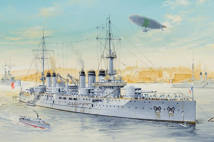
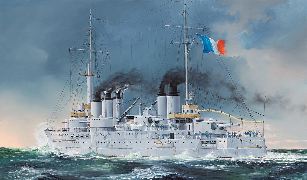
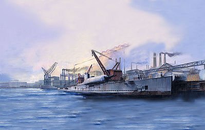
Heller only produced most of their ships at the scale of 1/400, which of course, was done long before 1/350 was adopted as the preferred scale for war ships. Now, HobbyBoss/Trumpeter has these two French Dreadnoughts: Voltaire and Condorcet. They also have Danton, but just the name of that individual is repulsing (he was instrumental in getting thousands of people be-headed after the Revolution). Another interesting vessel is the Submarine Surcouf, equipped with a massive gun and a plane: More modern, you have the large Cruiser/Battleship Strasboug and Dunkerque. Not much choice in 1/350, unfortunately. Yves
- 45 replies
-
- 5
-
-
- orp ślązak
- mirage hobby
- (and 2 more)
-
Jeanne d'Arc exists at the scale of 1/400, by Heller. Not sure if you can find it in 1/350 scale..... Yves
- 45 replies
-
- 2
-
-
- orp ślązak
- mirage hobby
- (and 2 more)
-
There is a lot of satisfaction at building a small boat. We always strive for the large and complicated vessel and lose our momentum in the process, most of the time. A small boat is easier built and can be very rewarding as proven by Duane's models. Yves
- 114 replies
-
- 4
-
-
- small
- Peterboro Canoe
- (and 2 more)
-
Amazing work and craftsmanship as always Greg. The Italian Cruiser Zara is an excellent and unusual choice too. Don't forget to do some French vessels too... 😉 Yves
- 45 replies
-
- 3
-
-
- orp ślązak
- mirage hobby
- (and 2 more)
-
Impressive!! It is like being on the deck, Mate. What a beautiful model, so precise and so perfect in every little details. Yves
- 315 replies
-
- 4
-
-
- master korabel
- avos
- (and 1 more)
-
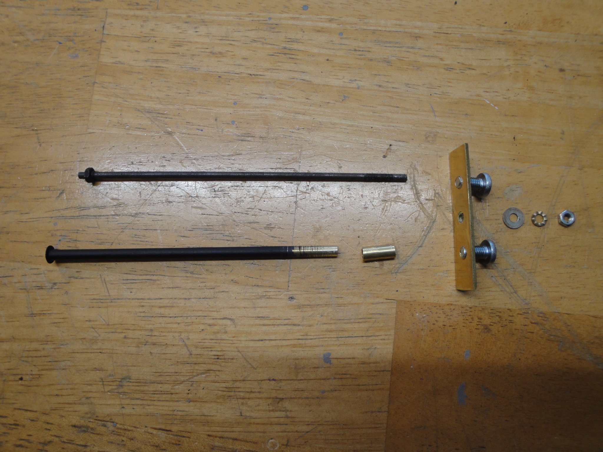
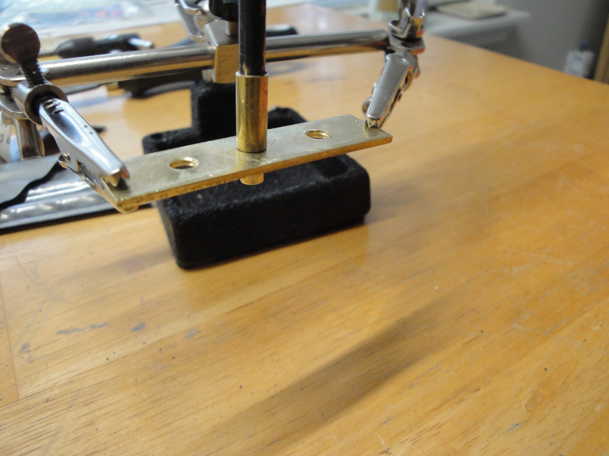
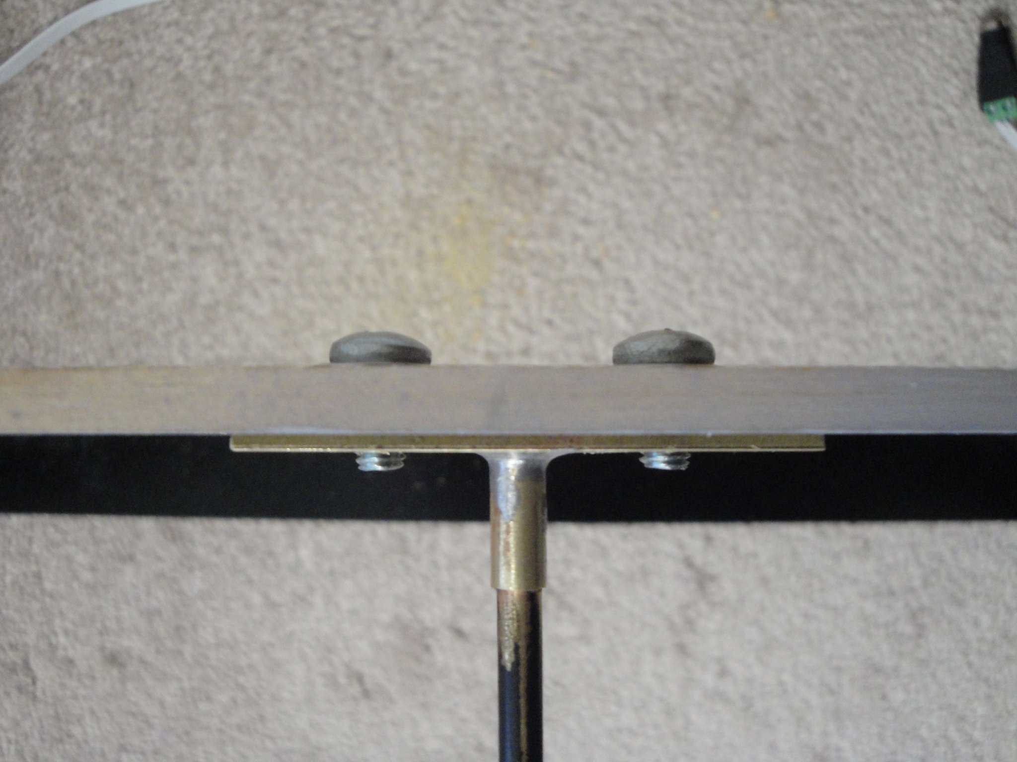
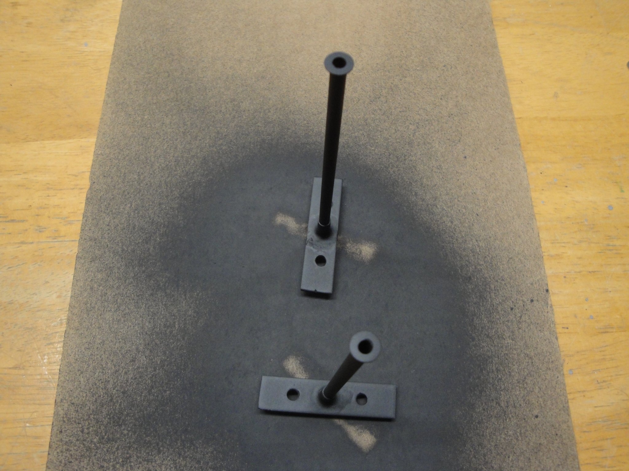
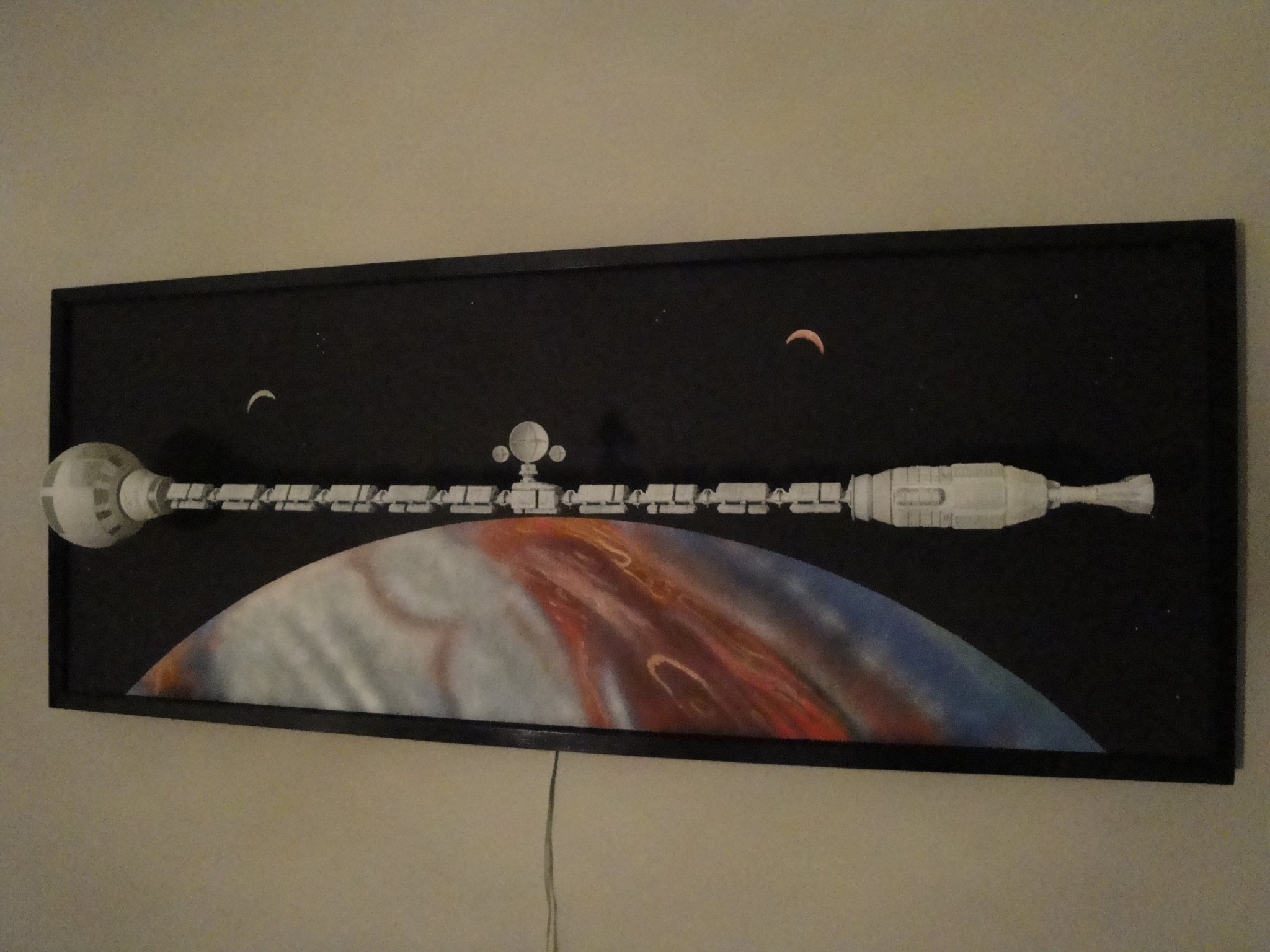
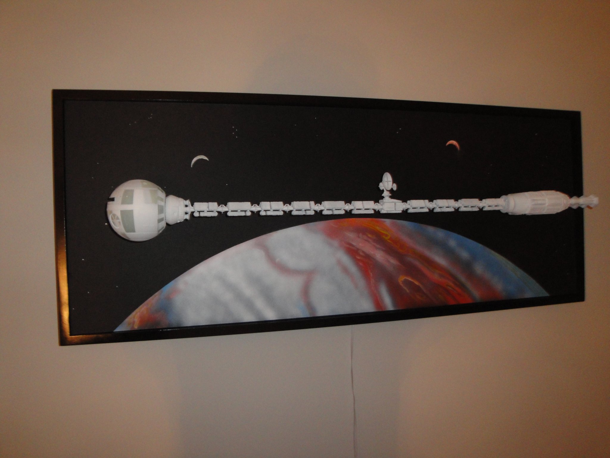
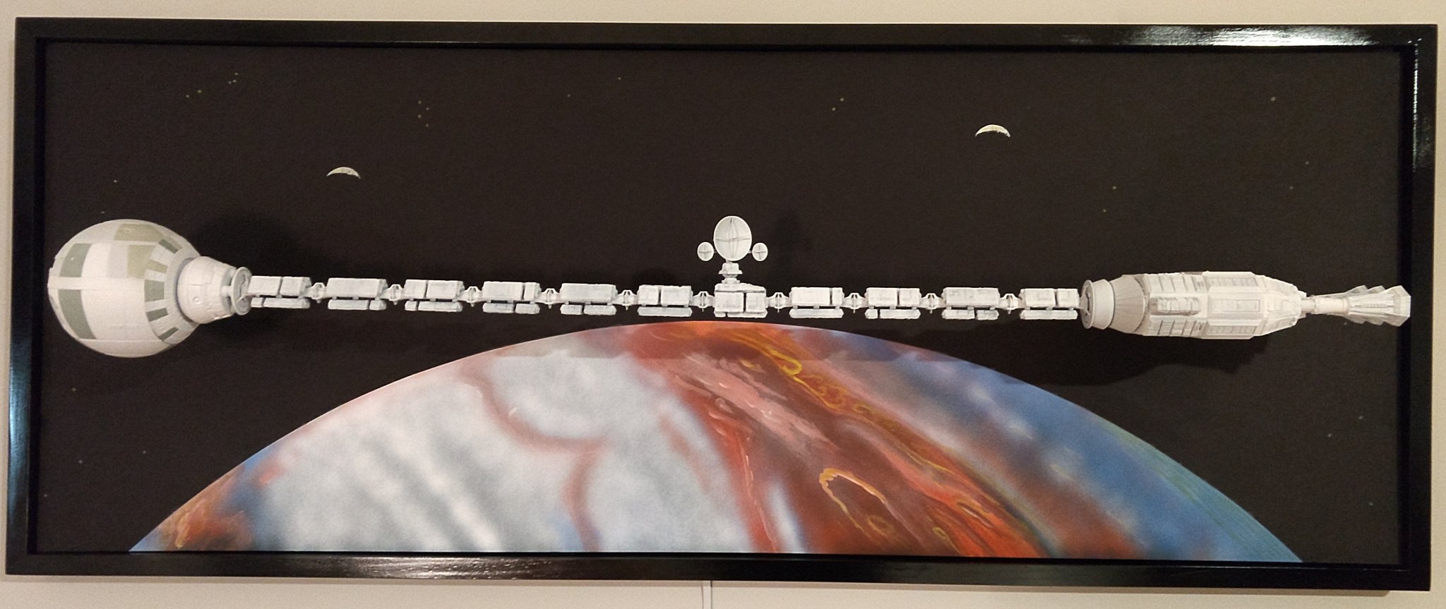
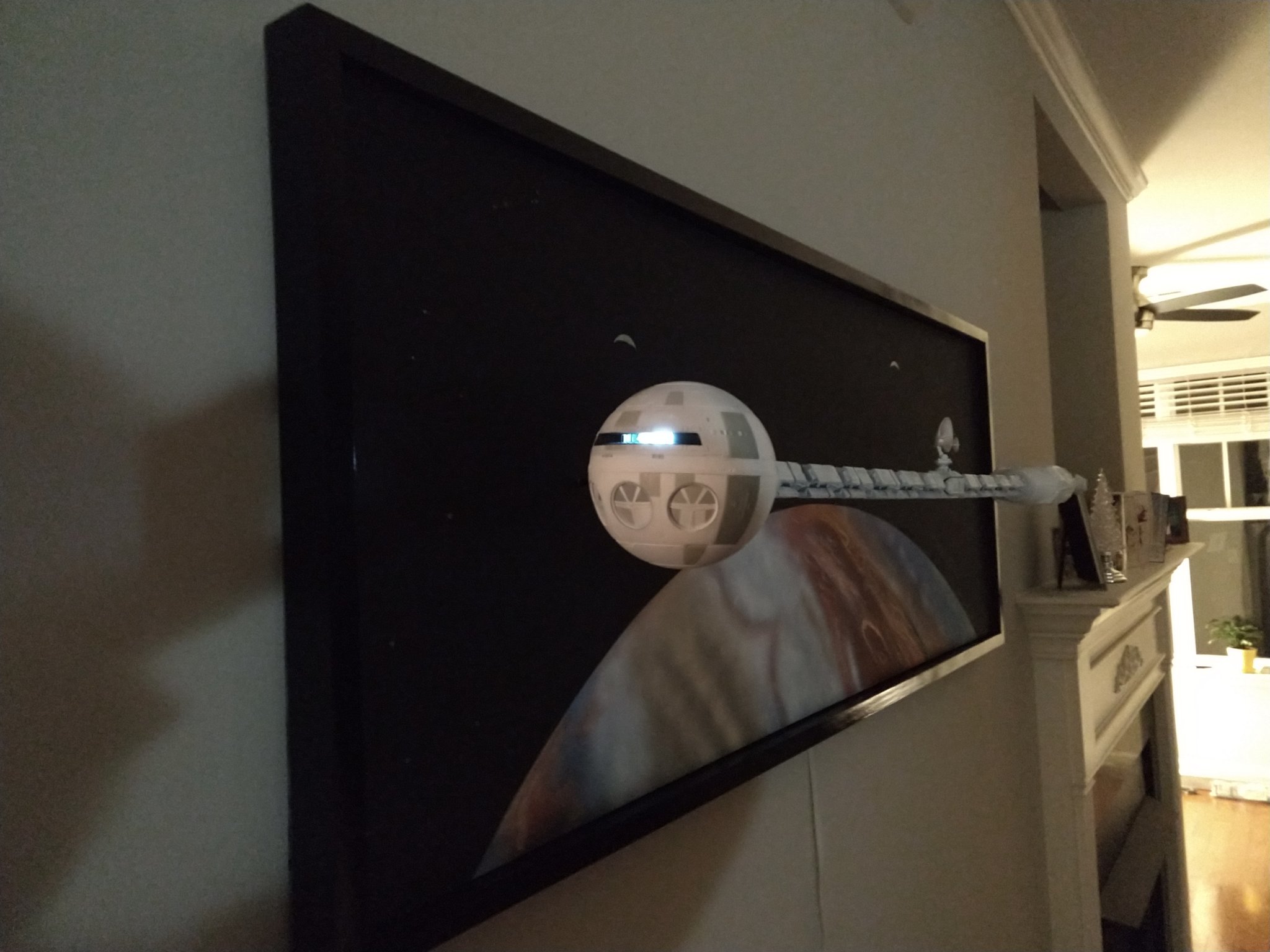
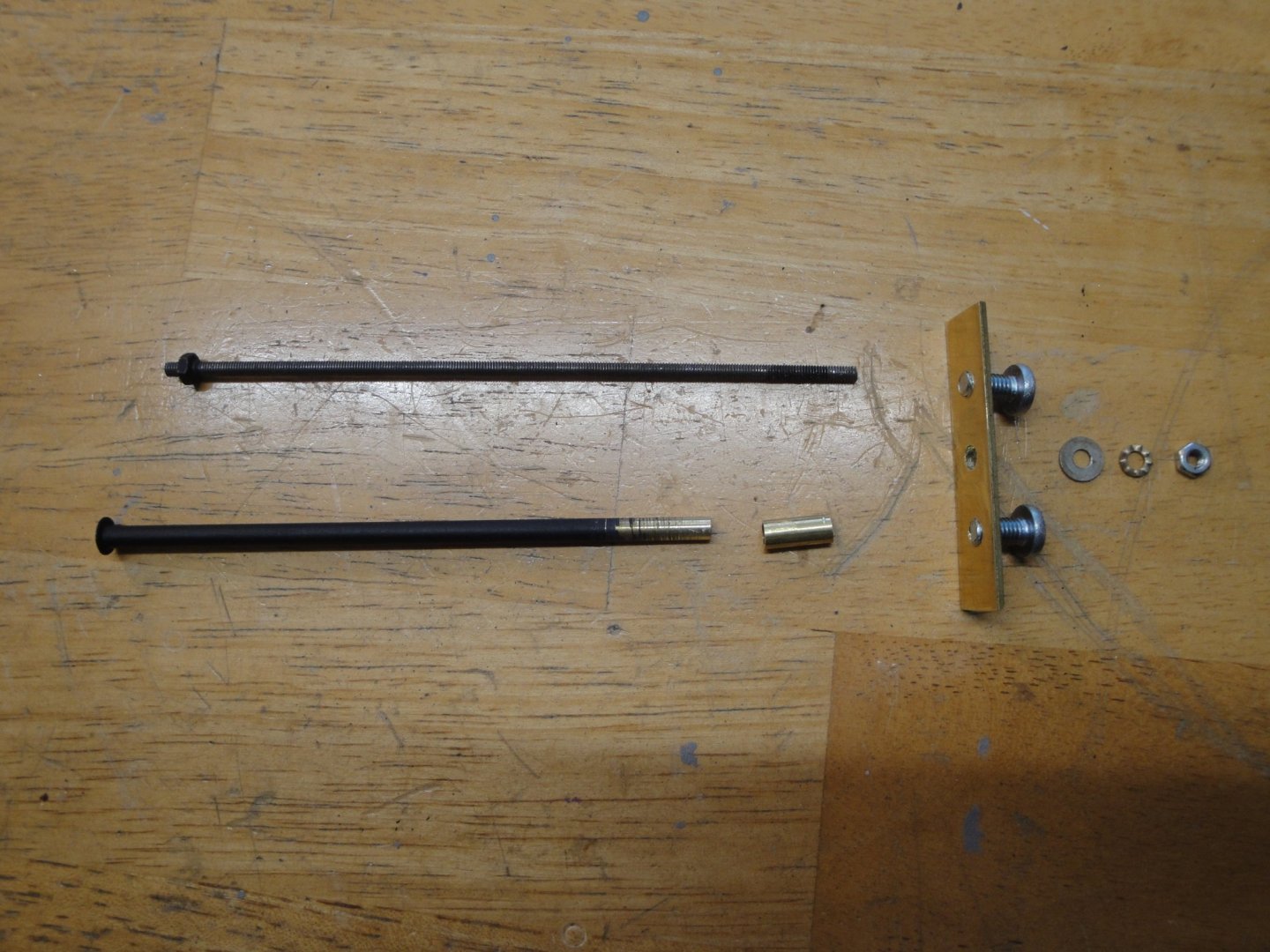
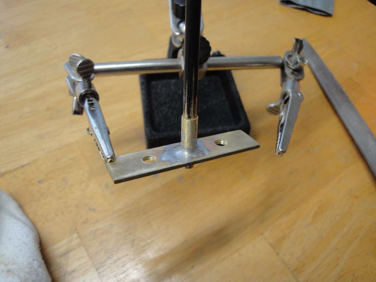
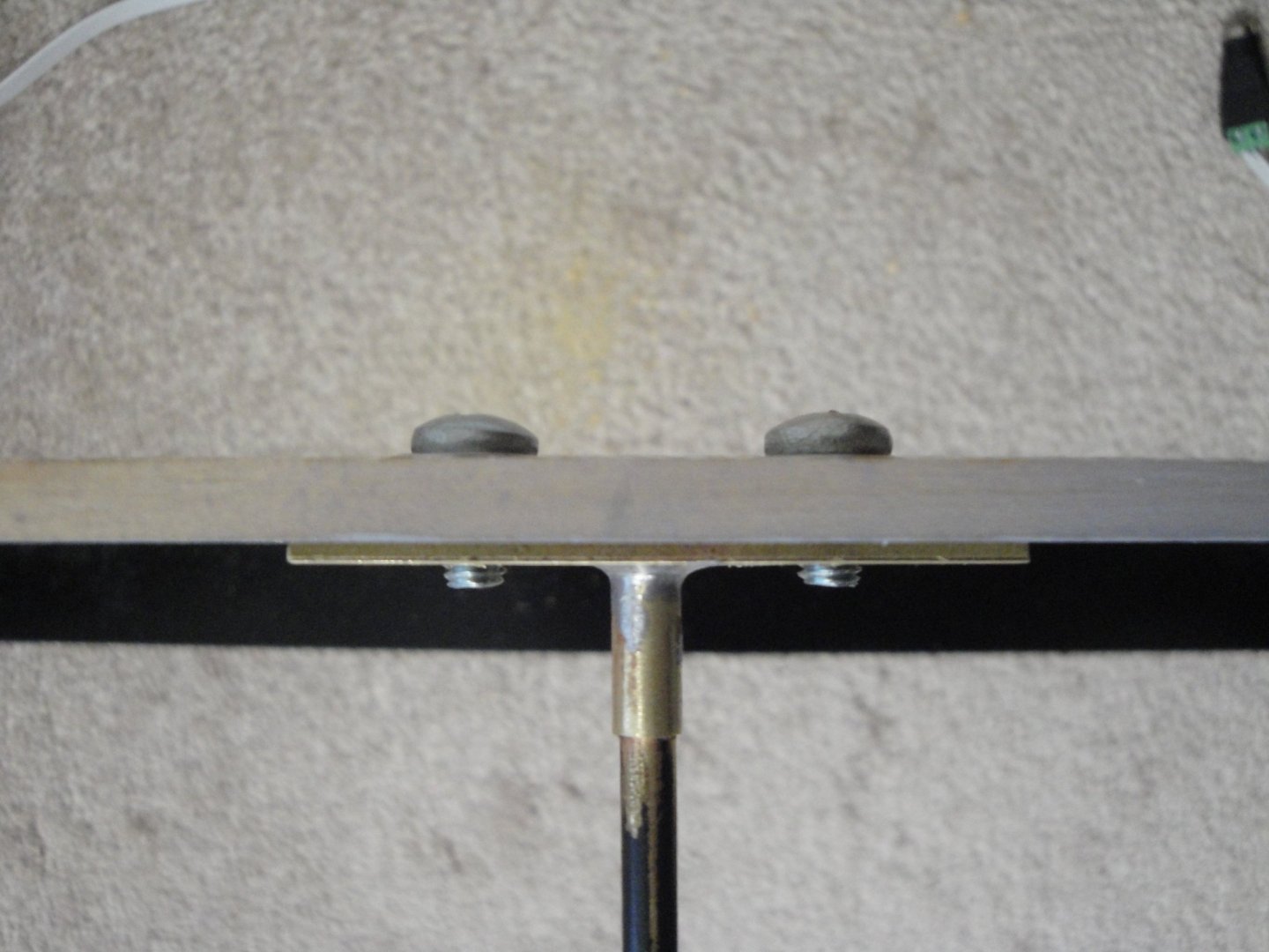
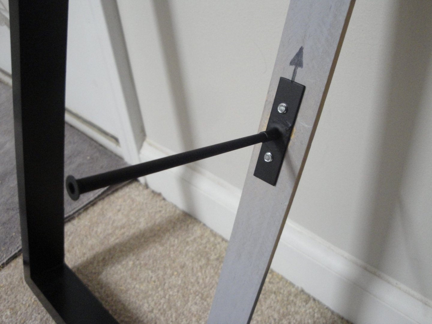
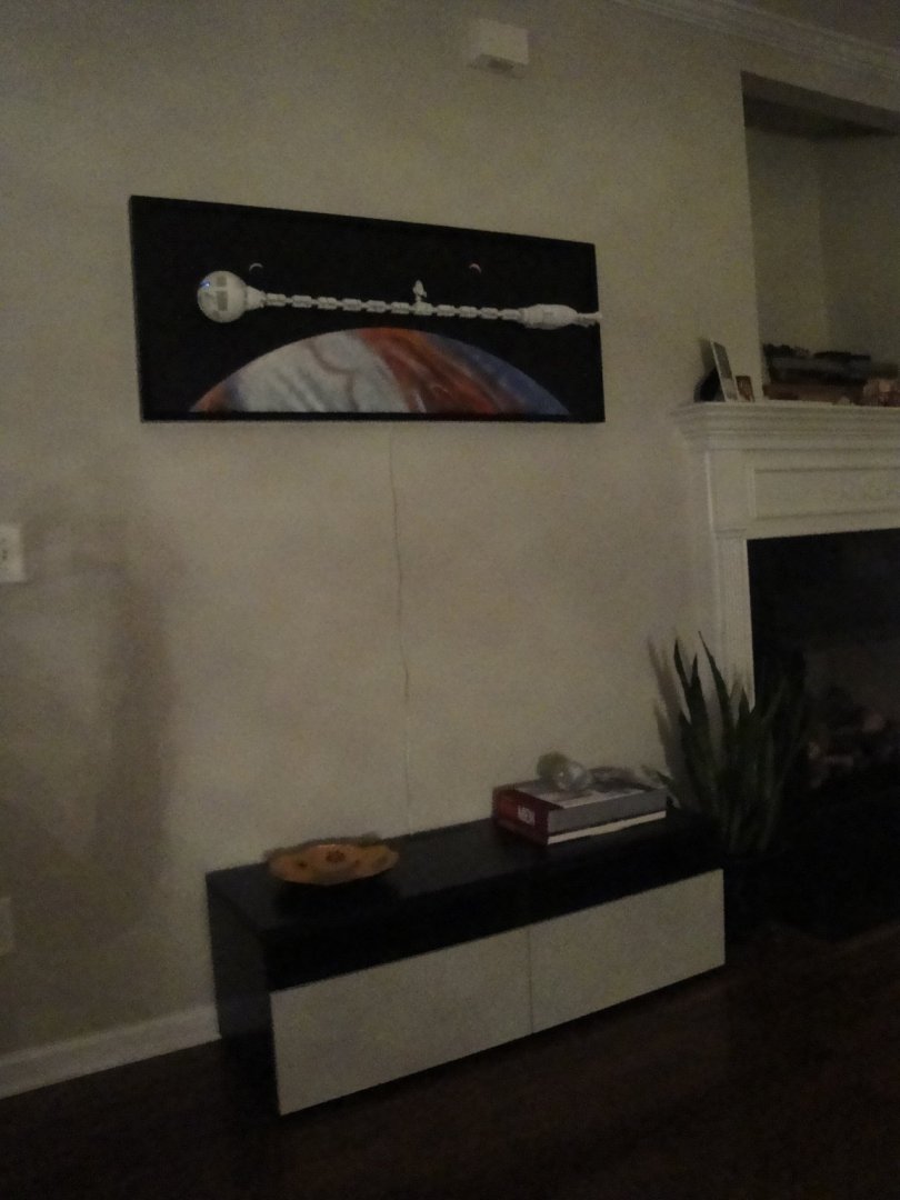
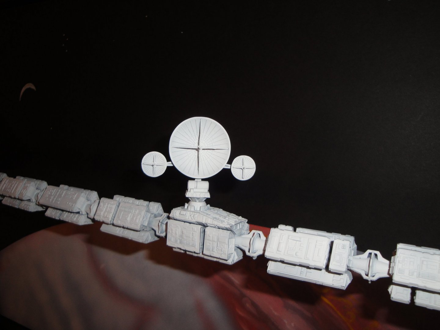
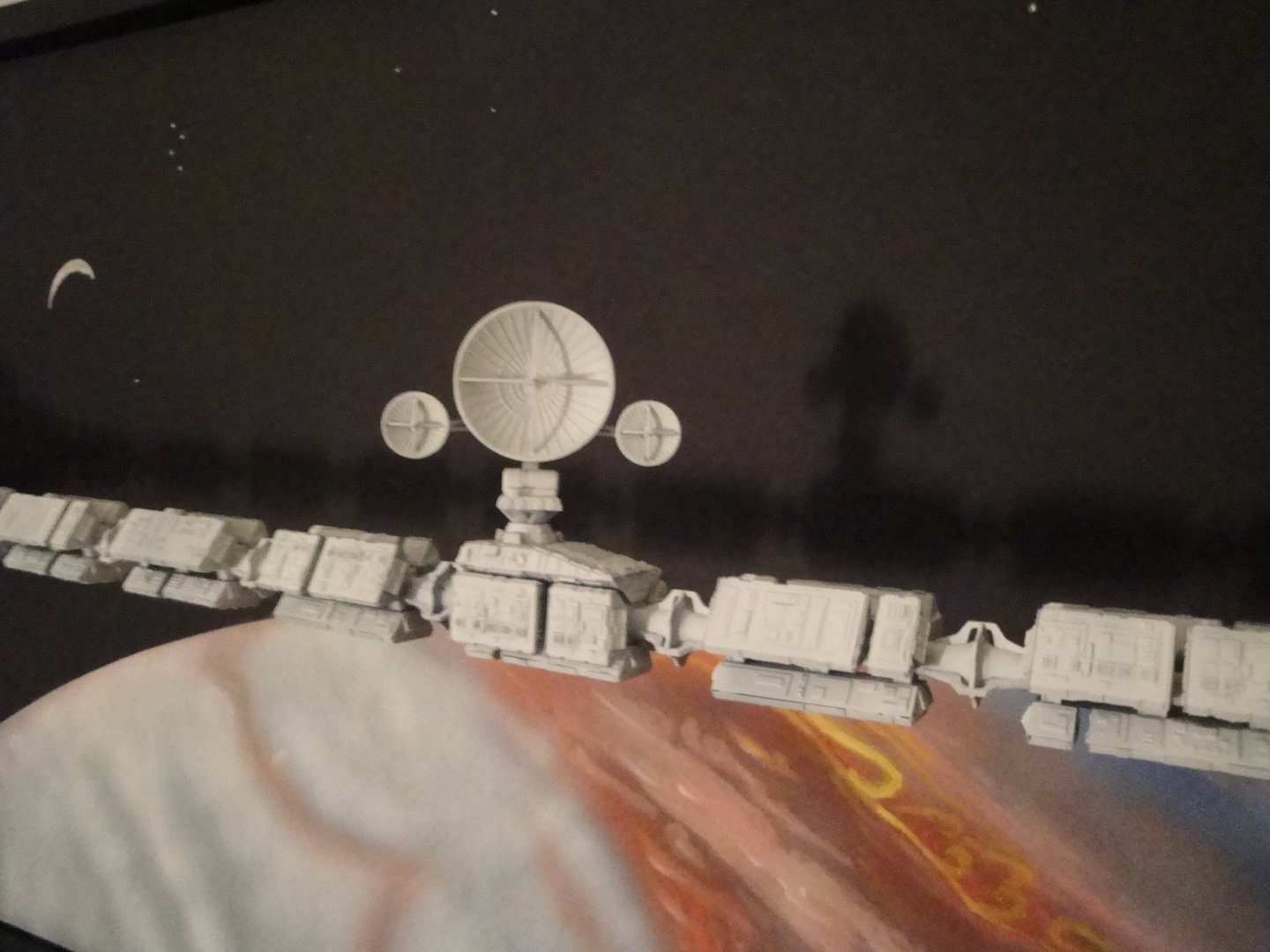
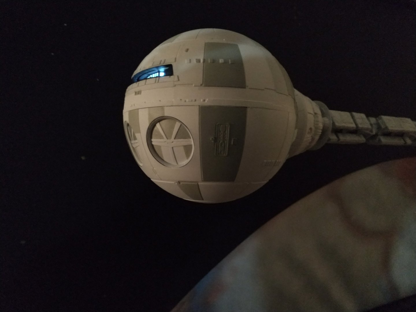
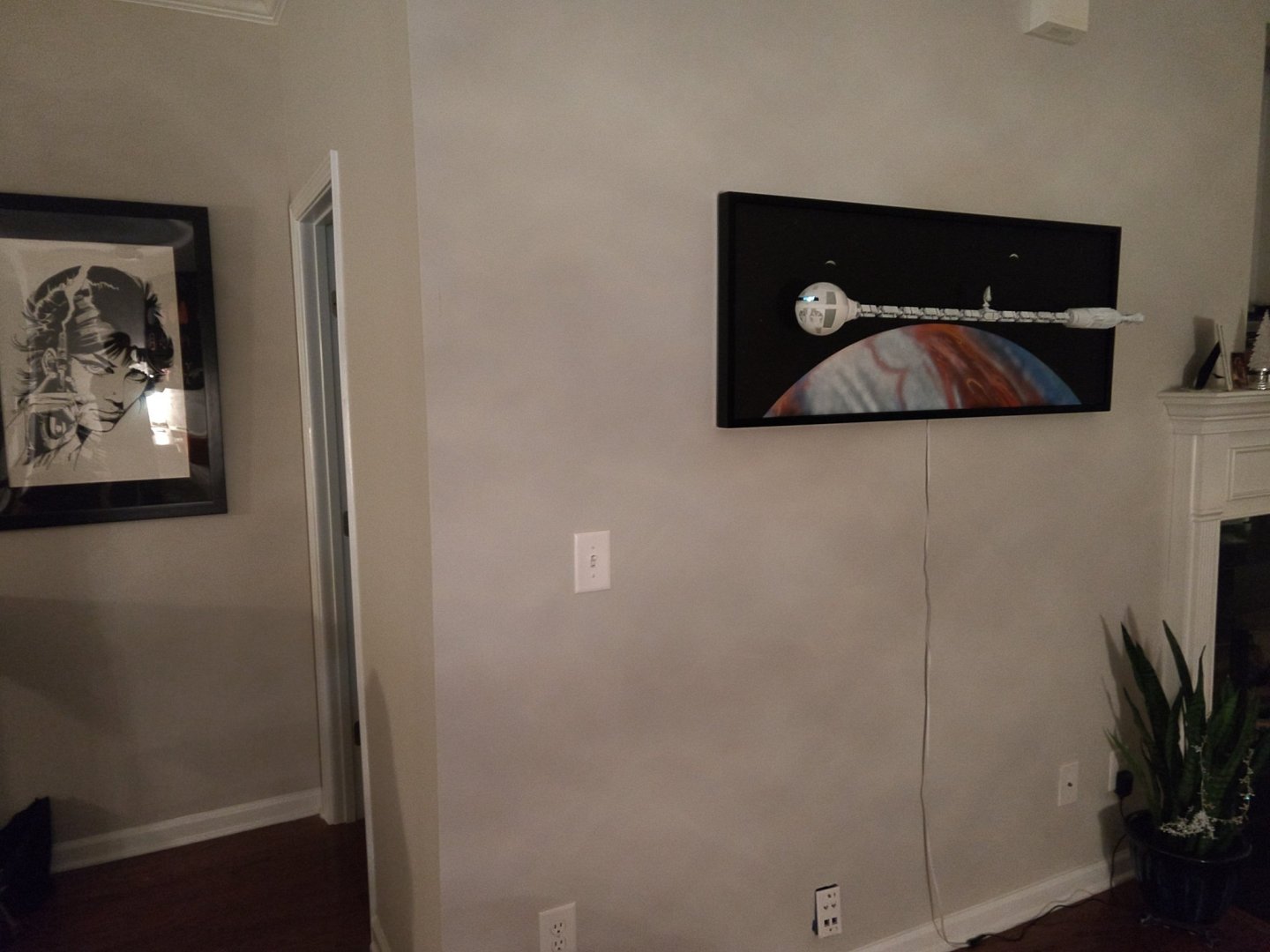
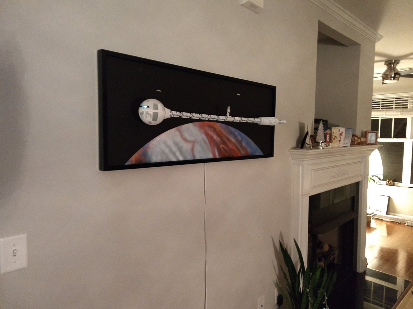
Well, I was not too happy with the anchoring system of this massive (and heavy) vessel. So, I decided to redo it and make it a lot more sturdy. There was a little bit of sagging and after a few days of standing by itself against the wall, it was not improving. So, this is what I came up with: You can see the idea: The black tube is going through the anchor plate (2 mm brass plate) and protruding enough to go through the wood brace of the frame. Another piece of tube is added at the juncture to increase the rigidity. The whole thing is soldered, resulting in a very rigid coupling. Now, you can hang a few pounds to the end of the black tube without any trace of sagging. This is the anchor assembled to the wooden frame. Two screws of 10-32 are holding the anchor plate: A little bit of spraying and it will be ready: The two moons are also slightly repainted and the shadow of the giant Jupiter planet is more realistic on each of them. The vessel is also more straight, due to the better anchoring: End of that very pleasant project. Everybody that visits has been enjoying the art piece and I hope this Log will entice you to come up with something unusual for this great kit. Yves


- 119 replies
-
- 11
-
-
May I suggest a few: St Antoine l’Abbaye Saint martin Villefranche Villeneuve there are so many places in France... Yves
-
Excellent and unusual choice of boat. I love these Mediterranean ships and your choice of 1/36 scale is going to turn it into a very sizable model. Beautiful work. This is perfection. Yves
-
Nils, I understand your dilemma. Maybe the Preiser will become available again, in the near future. What you could also do, is shorten the legs of the benches, to make them look more realistic. Yves
- 38 replies
-
- 2
-
-
- billing boats
- hjejlen
- (and 2 more)
-
Nils, there is something wrong with these seating passengers. Either they all have short legs, or the benches are way too high or they are not at the proper scale for this boat. It is disturbing on an otherwise beautiful model. Are these little people, Chinese toys? Since you live in Europe, you should look for PREISER figures at 1/48 scale. They are by far the best quality. Yves
- 38 replies
-
- 3
-
-
- billing boats
- hjejlen
- (and 2 more)
-
You are very kind 🙂 Yves
-
It does to me too. This will be patched and re-painted. Yves
-
B-25J Mitchell by Tom E - Revell - 1:48 Scale - PLASTIC
yvesvidal replied to Tom E's topic in Non-ship/categorised builds
Tom, It looks like you have been spending some serious money recently. I call that an investment. Yves -
This will be giant and very heavy.....Excellent idea to cut it in three modules. Yves
-
Amazing results for a plastic model. Kudos. That is a beautiful boat with a Latin rigging. Yves
- 40 replies
-
- 5
-
-
- la tartane
- heller
- (and 1 more)
-
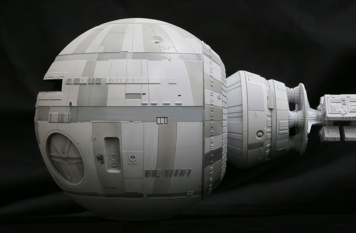
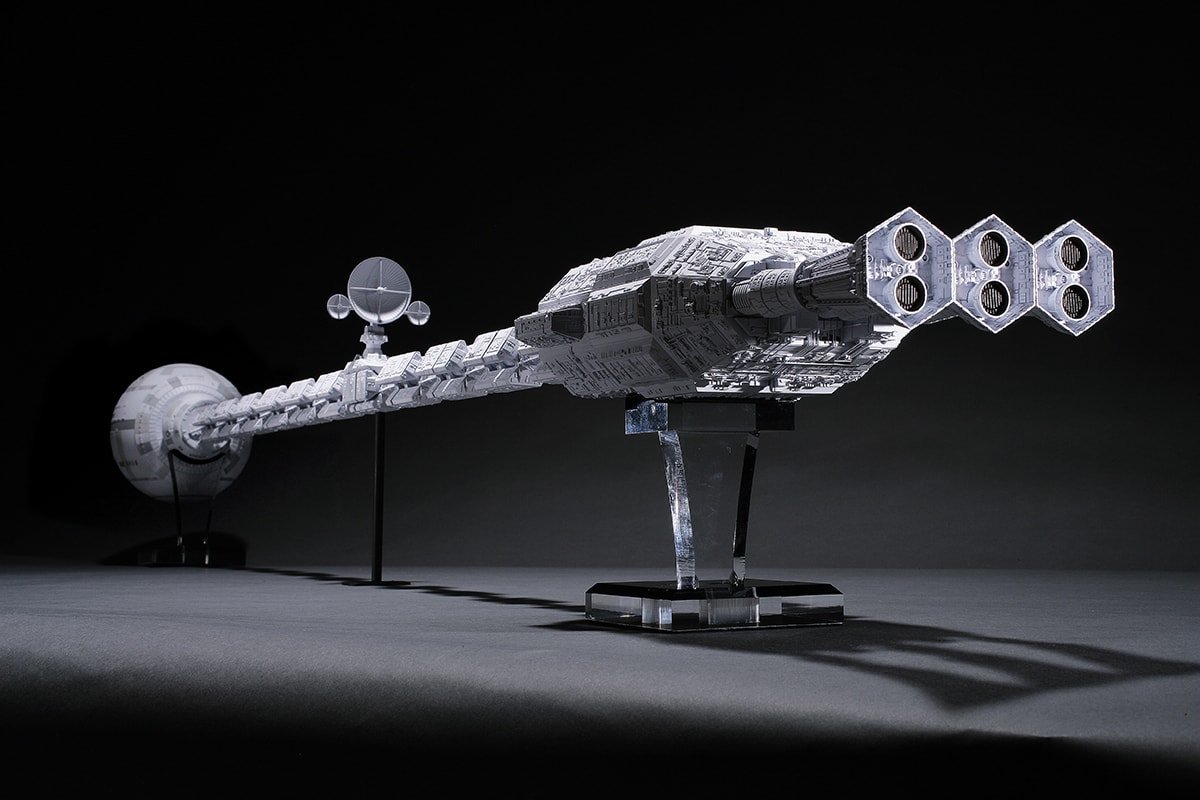
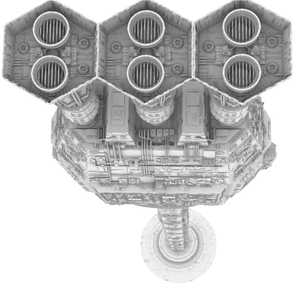
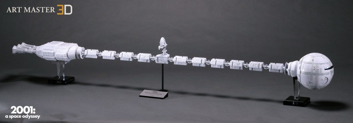
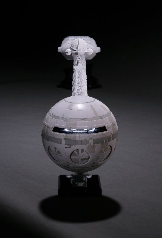
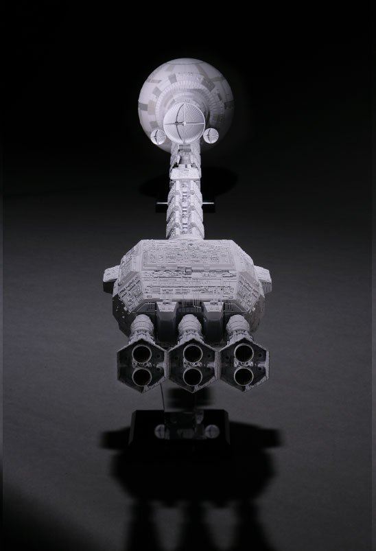
For those of you who are as fanatic as I am about the 2001 Discovery ship, there is a fantastic reproduction made by a Japanese company: https://discovery-one.hlj.com/ Their model is exquisitely detailed and goes way beyond what Moebius did with their 1/144 kit. The ART MASTER 3D model comes fully assembled and painted by Japanese artist. It measures 5 feet 4 long and is a replica at the scale of 1/10th of the original prop created by Kubrick and his team. The price is way crazy at more than $14,300 each plus an additional $650 shipping fees. Unfortunately, even if you had the money, the list of orders is already closed. Below are some pictures of the incredible ART MASTER 3D model: A truly magnificent piece of art. Yves
-
Thank you guys for the encouragement and compliments. I truly appreciate every one of them. Yves
-
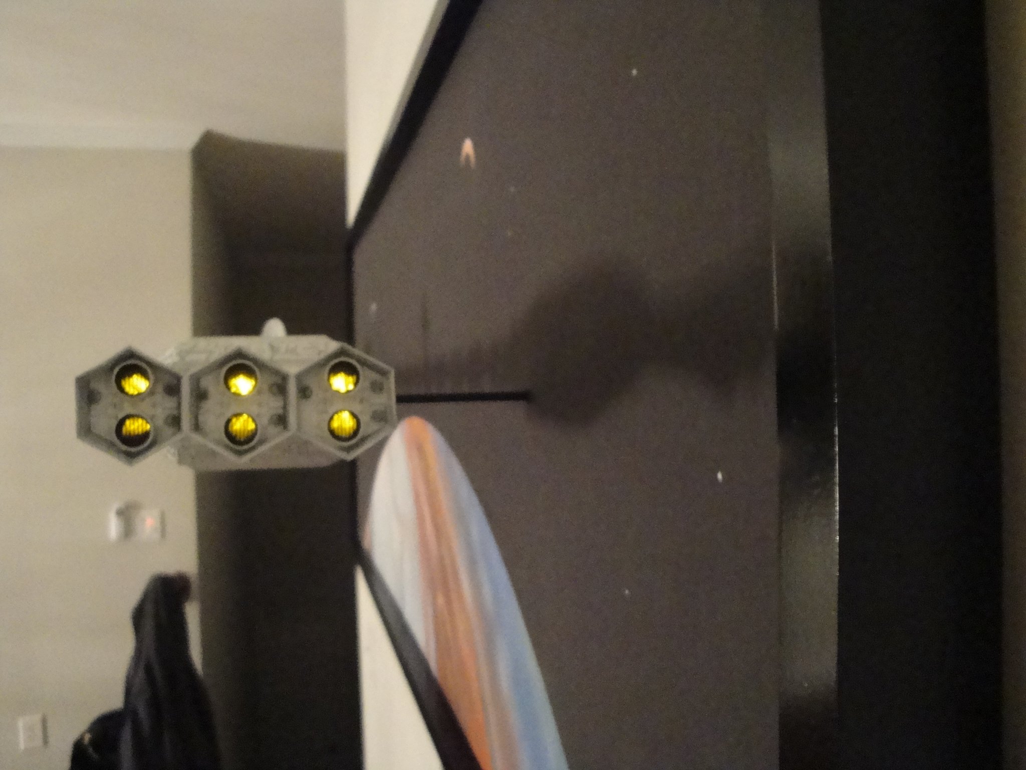
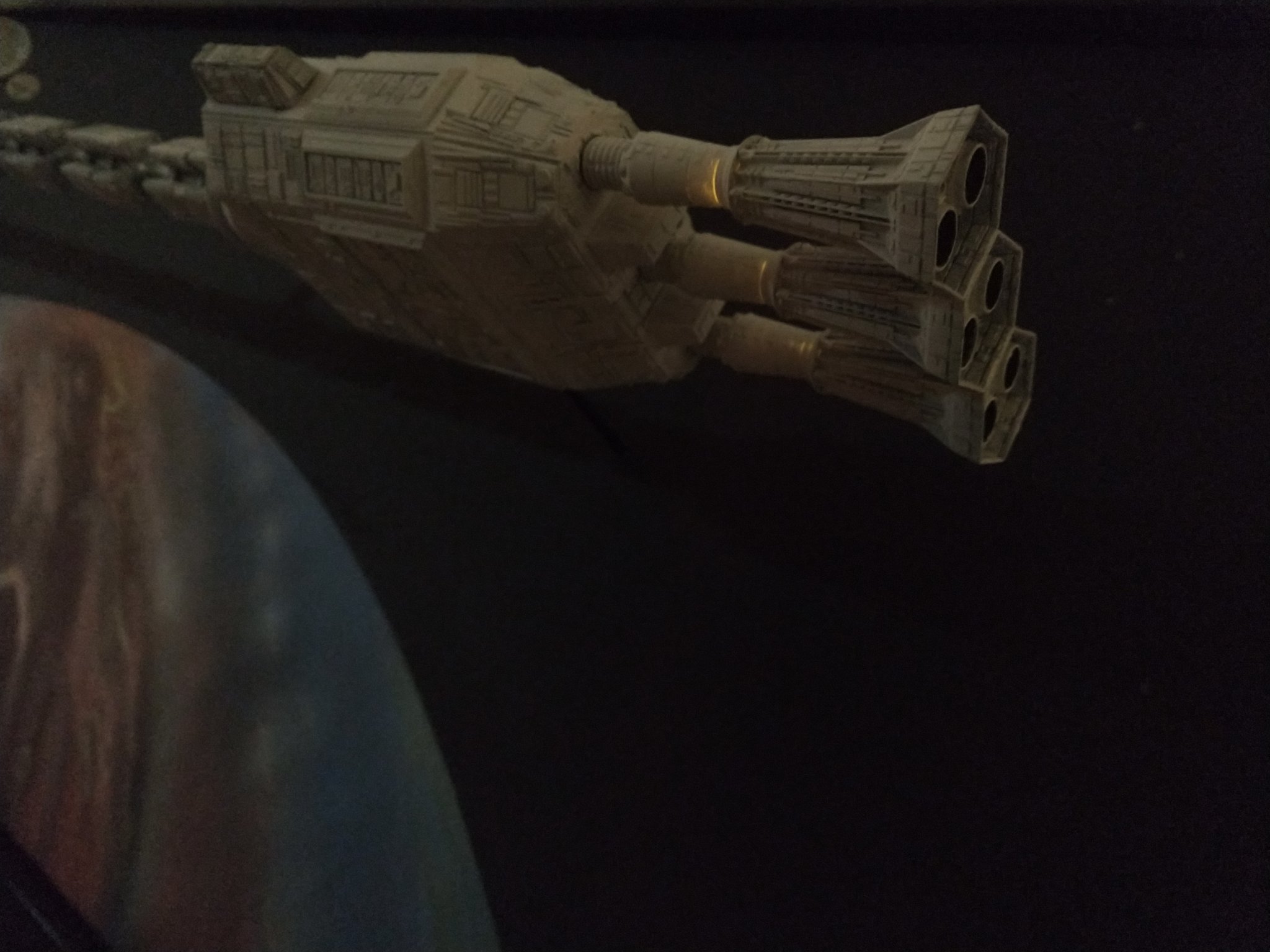
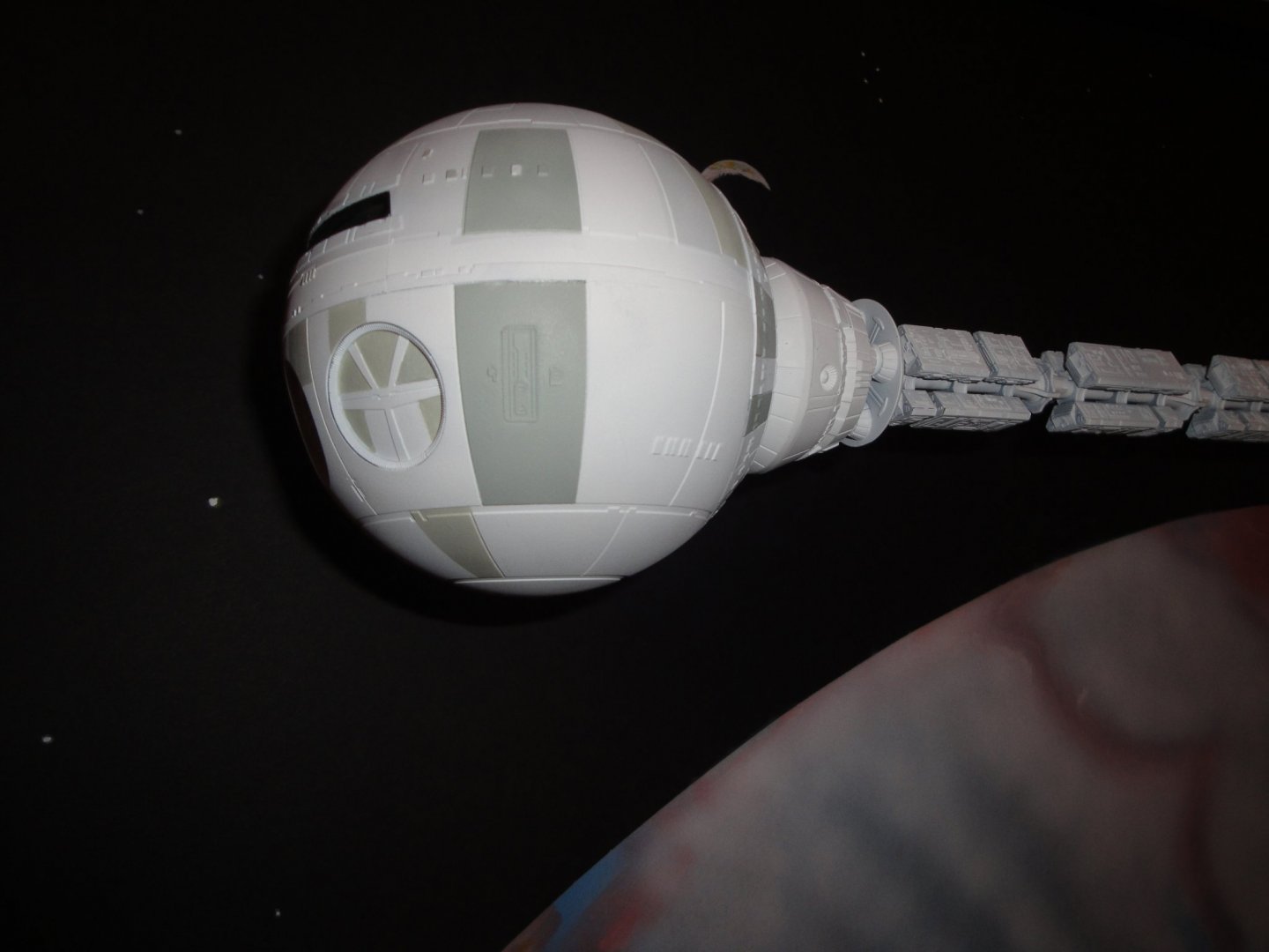
None of the above :-) The Discovery pictures are from my Android phone. Everything about the submarine is from an old Sony camera, unable to focus at short distance. Yves
-
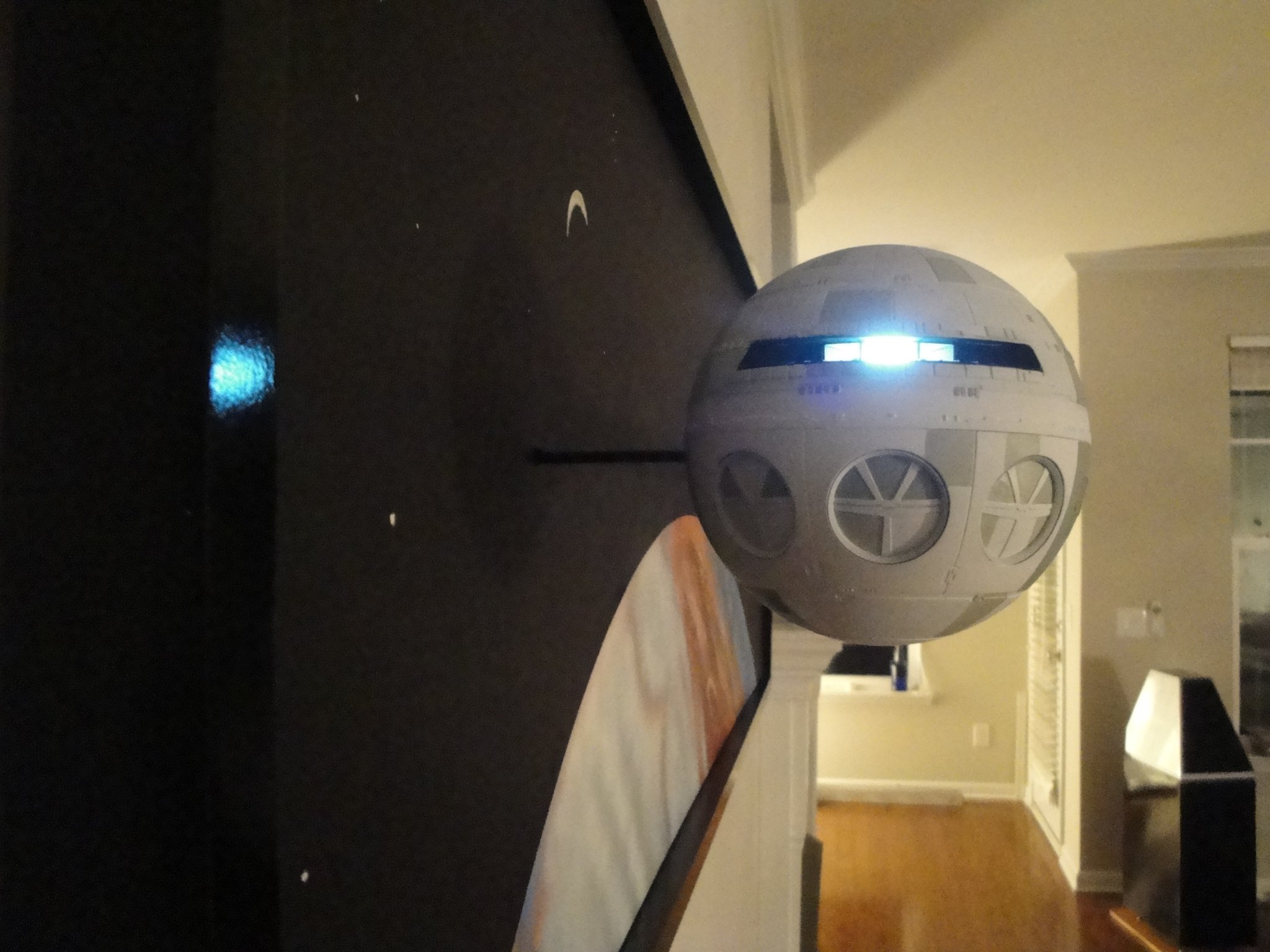
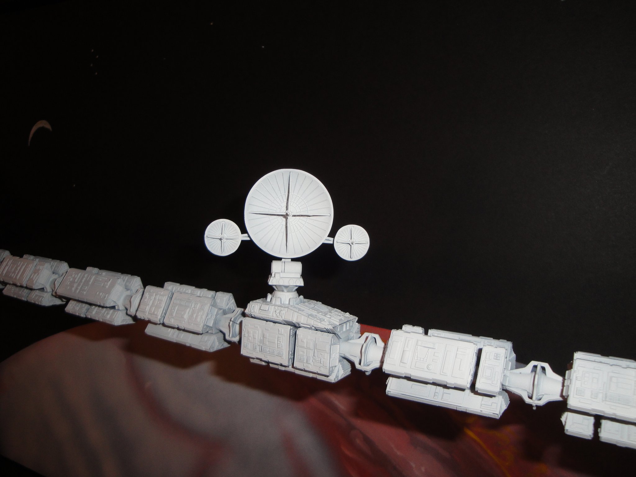
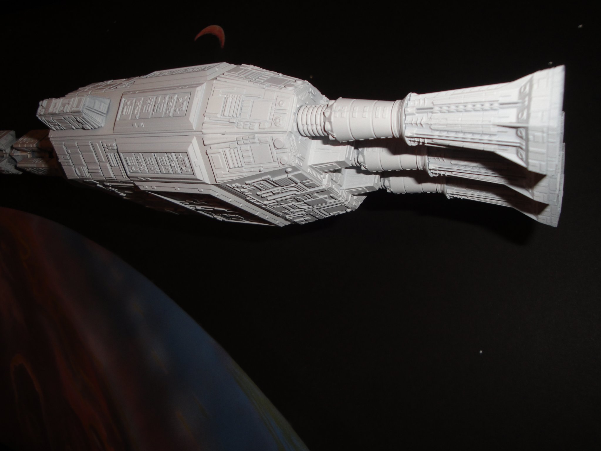
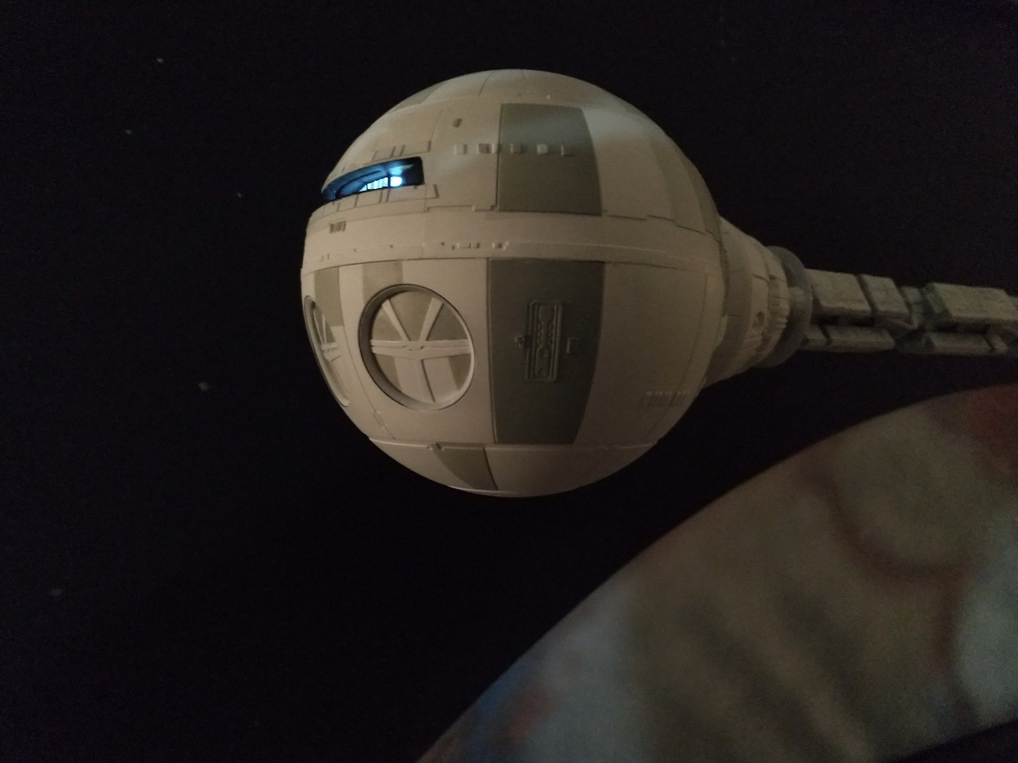
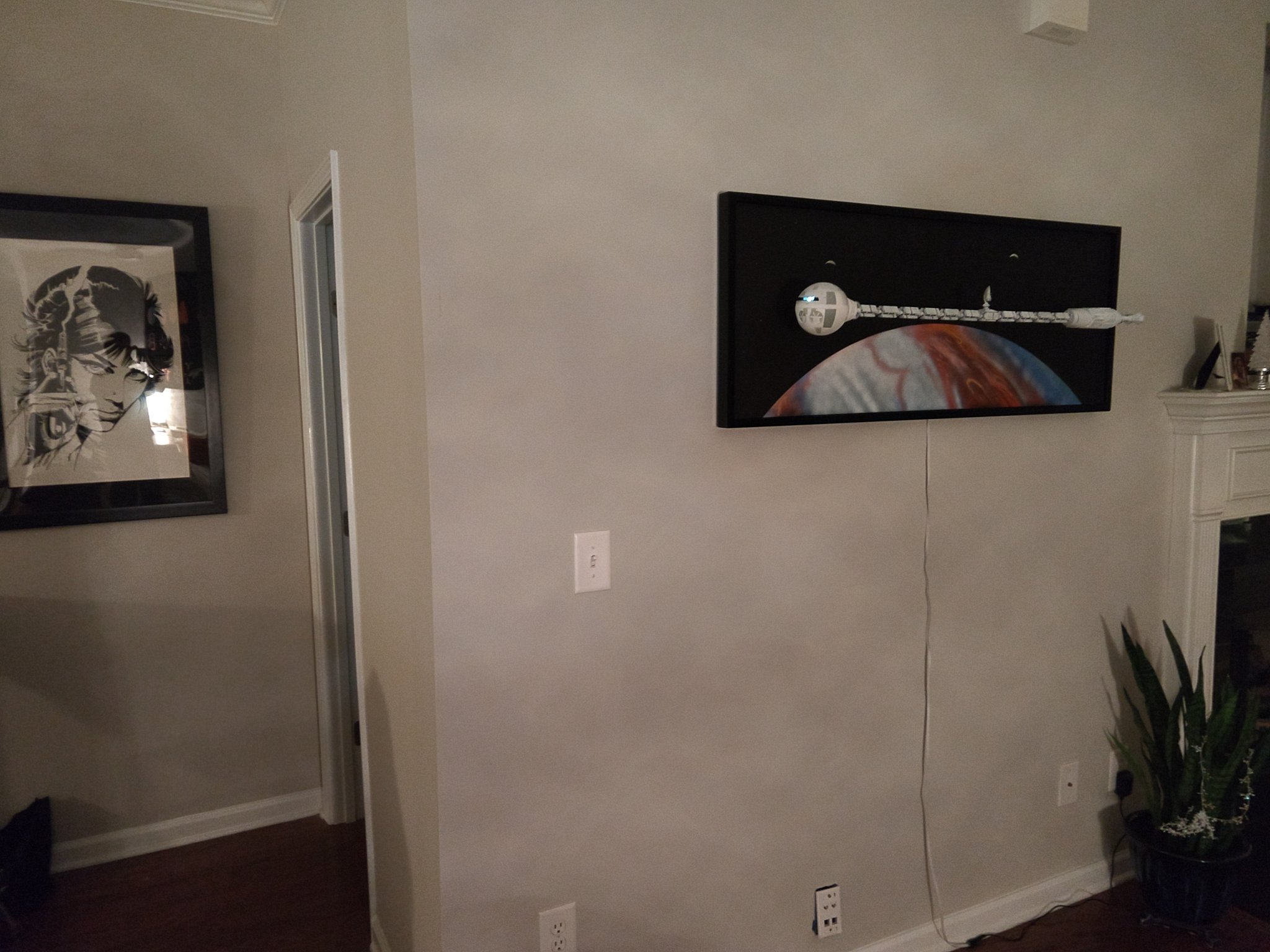
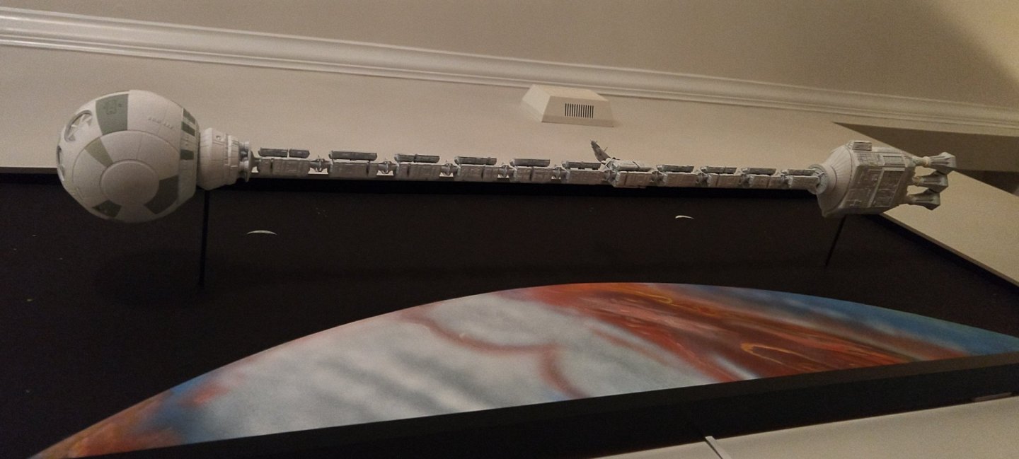
Well, the deep space "submarine" Discovery XD-1 is now completed: It will be a little while before I go back to the U-Boot but who knows..... the urge may come back, quickly. Yves
- 760 replies
-
- 17
-
-
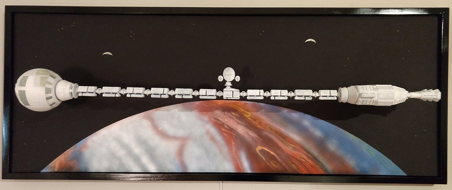
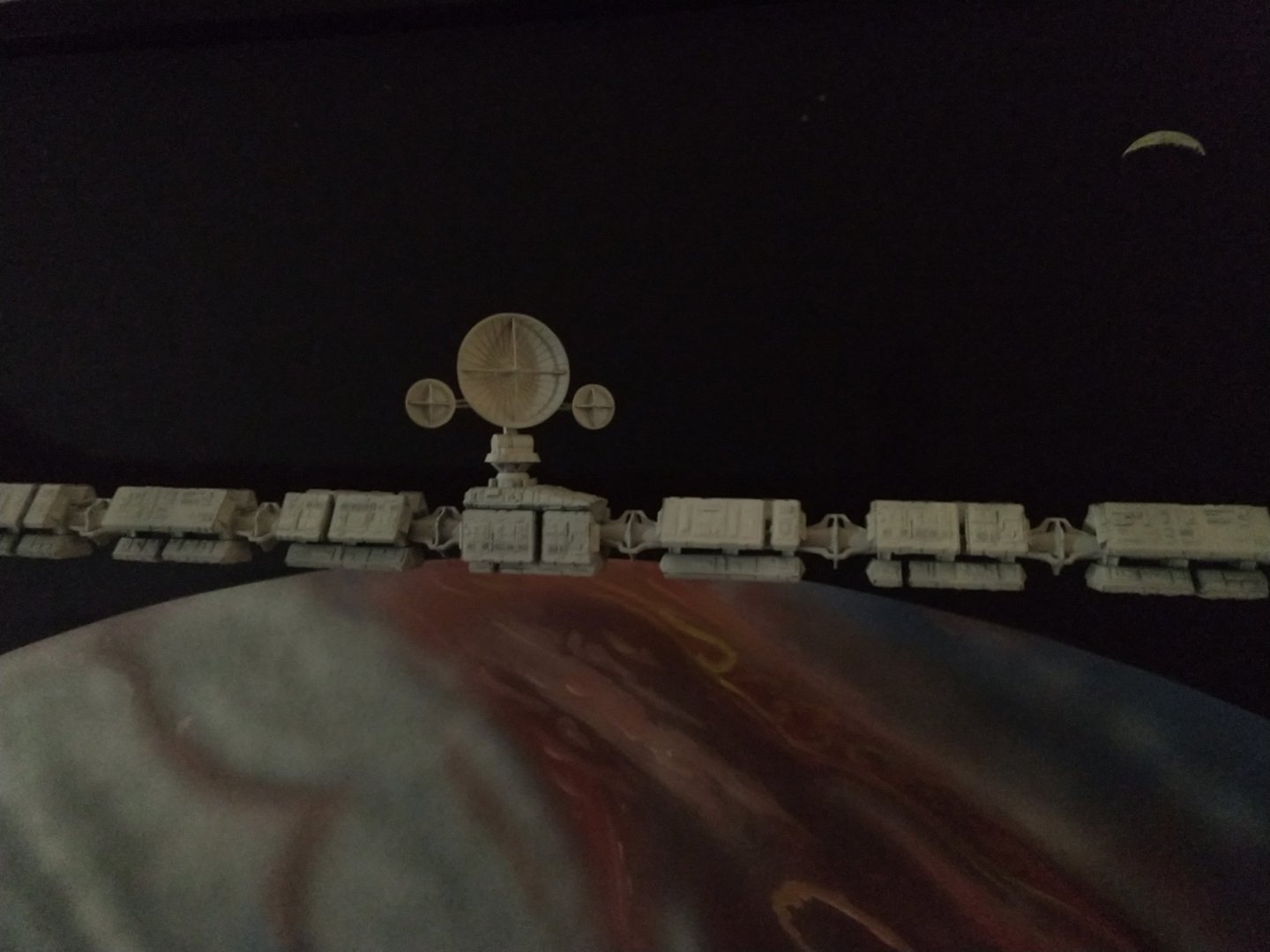
And we finally come to an end of this project. Discovery is now orbiting the giant Planet Jupiter I hope you have enjoyed that project. Yves


- 119 replies
-
- 24
-
-
Superb work of patience and Love. Yves