HOLIDAY DONATION DRIVE - SUPPORT MSW - DO YOUR PART TO KEEP THIS GREAT FORUM GOING! (78 donations so far out of 49,000 members - C'mon guys!)
×


yvesvidal
-
Posts
3,607 -
Joined
-
Last visited
Content Type
Profiles
Forums
Gallery
Events
Everything posted by yvesvidal
-
 That Putty is amazing. Thanks for posting that video CDW. I am currently using Squadron Petroleum based Putty, but I do not like it: dries too fast, smells and a pain in the neck to clean the tools. Yves
 -
Looking really good. So realistic. Yves
-
Are you a jeweler by trade? This is amazing. Yves
-
Trident Models has been teasing us with gorgeous pictures of the Alert Model, but no information on the kit, its price, availability or even if it will be allowed on this forum, has come to light. There are two previous threads on that Trident Models Alert kit, and both ended up nowhere. We need facts!!! Yves
-
Absolutely stunning. I think "Master Korabel" should use your model for the box artwork and pictures of the finished model, in the instructions. What a Masterpiece!!! Yves
- 315 replies
-
- 2
-

-
- master korabel
- avos
- (and 1 more)
-
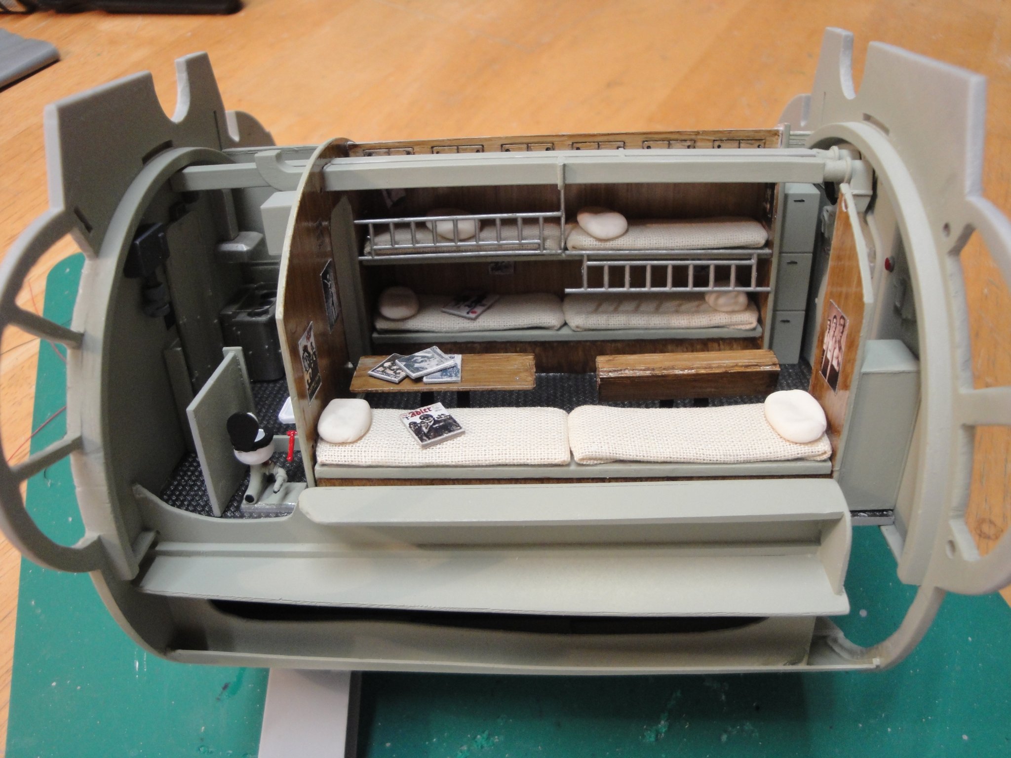
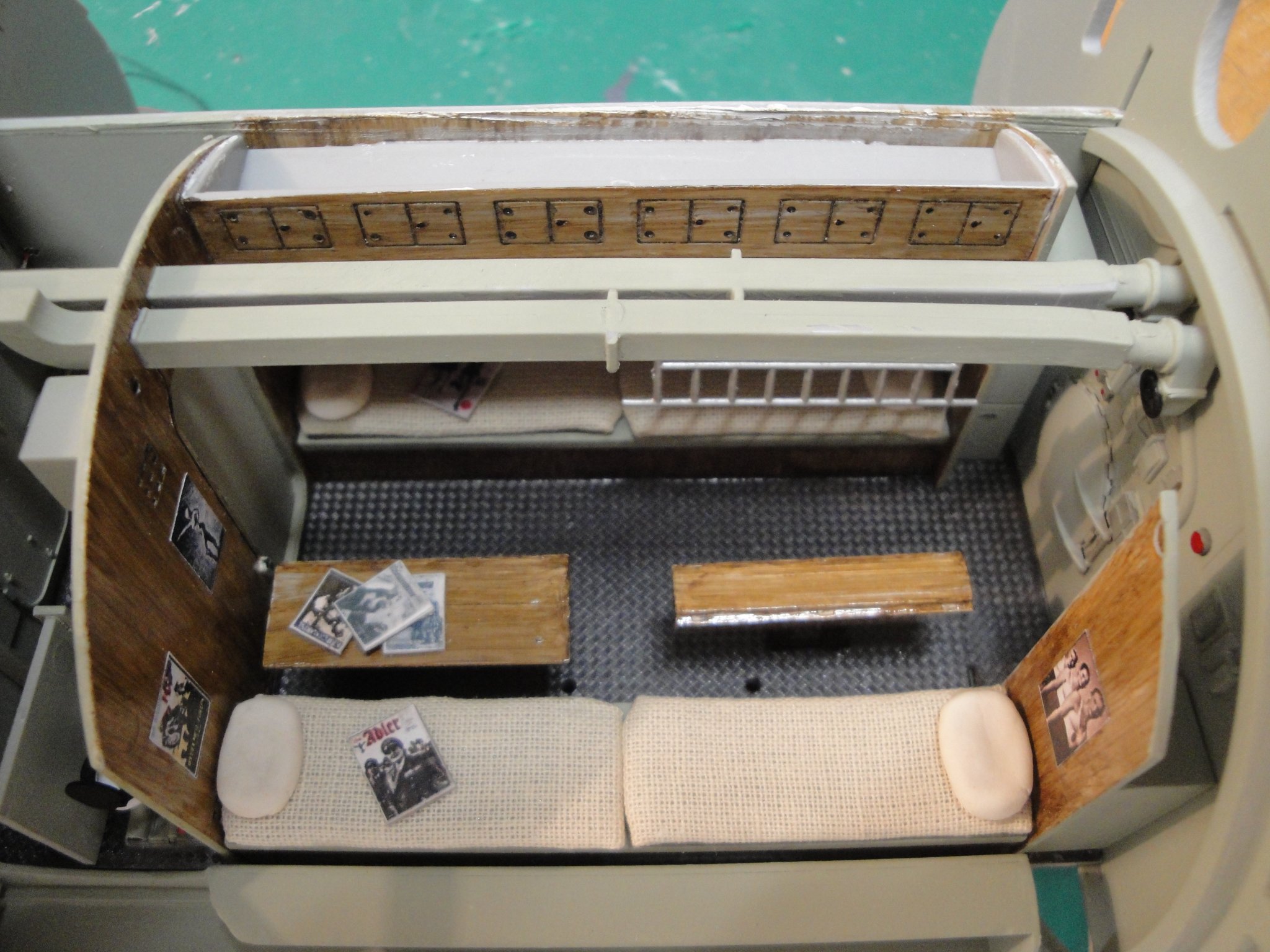
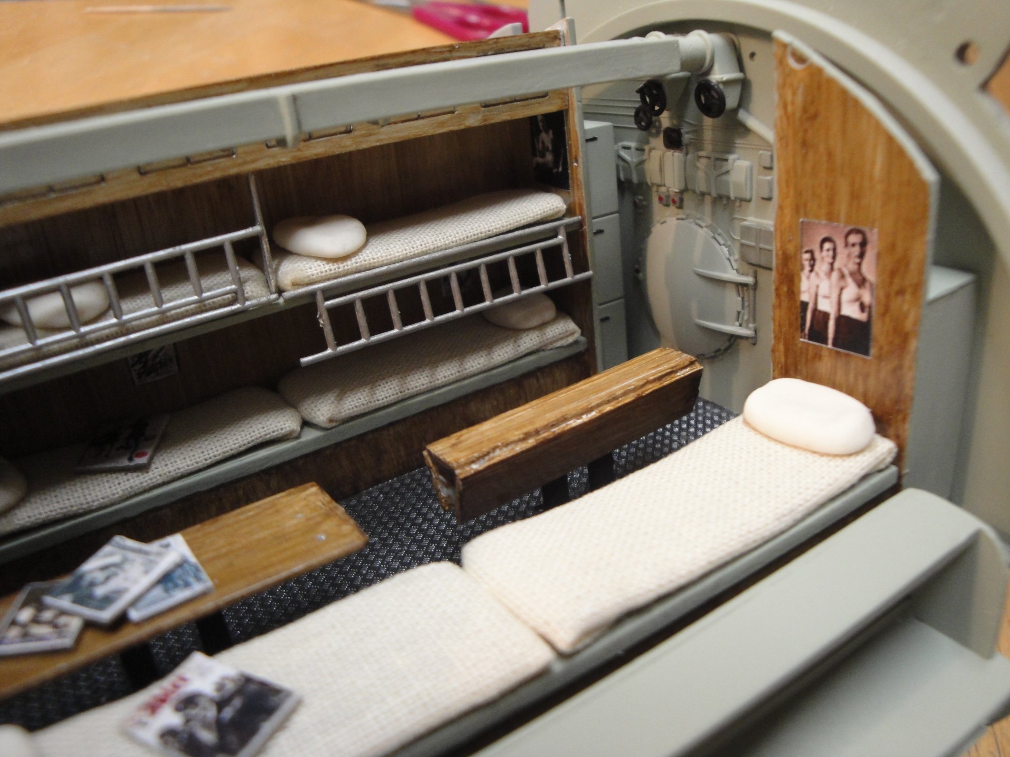
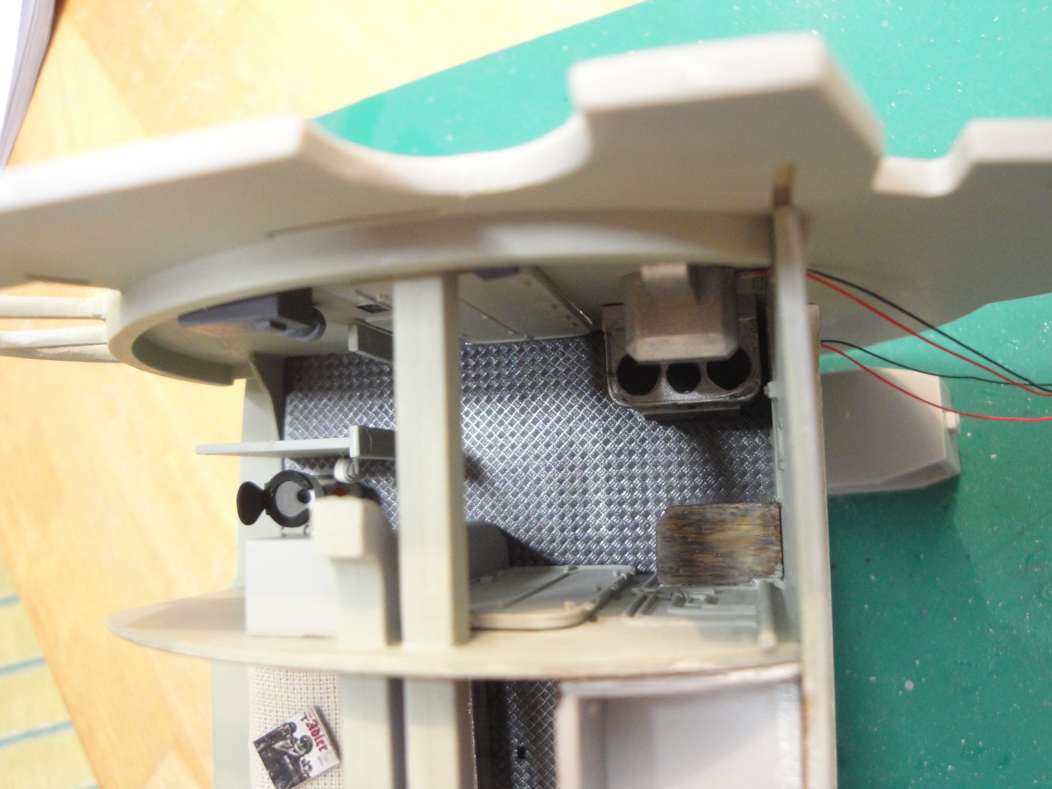
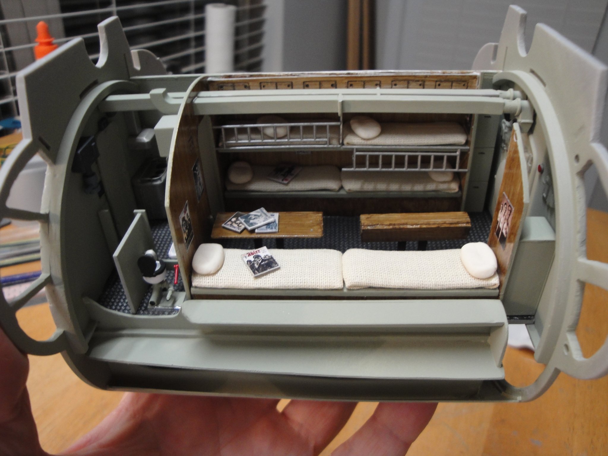
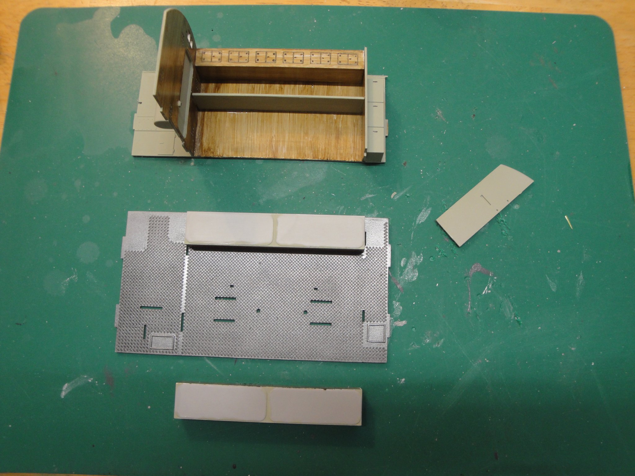
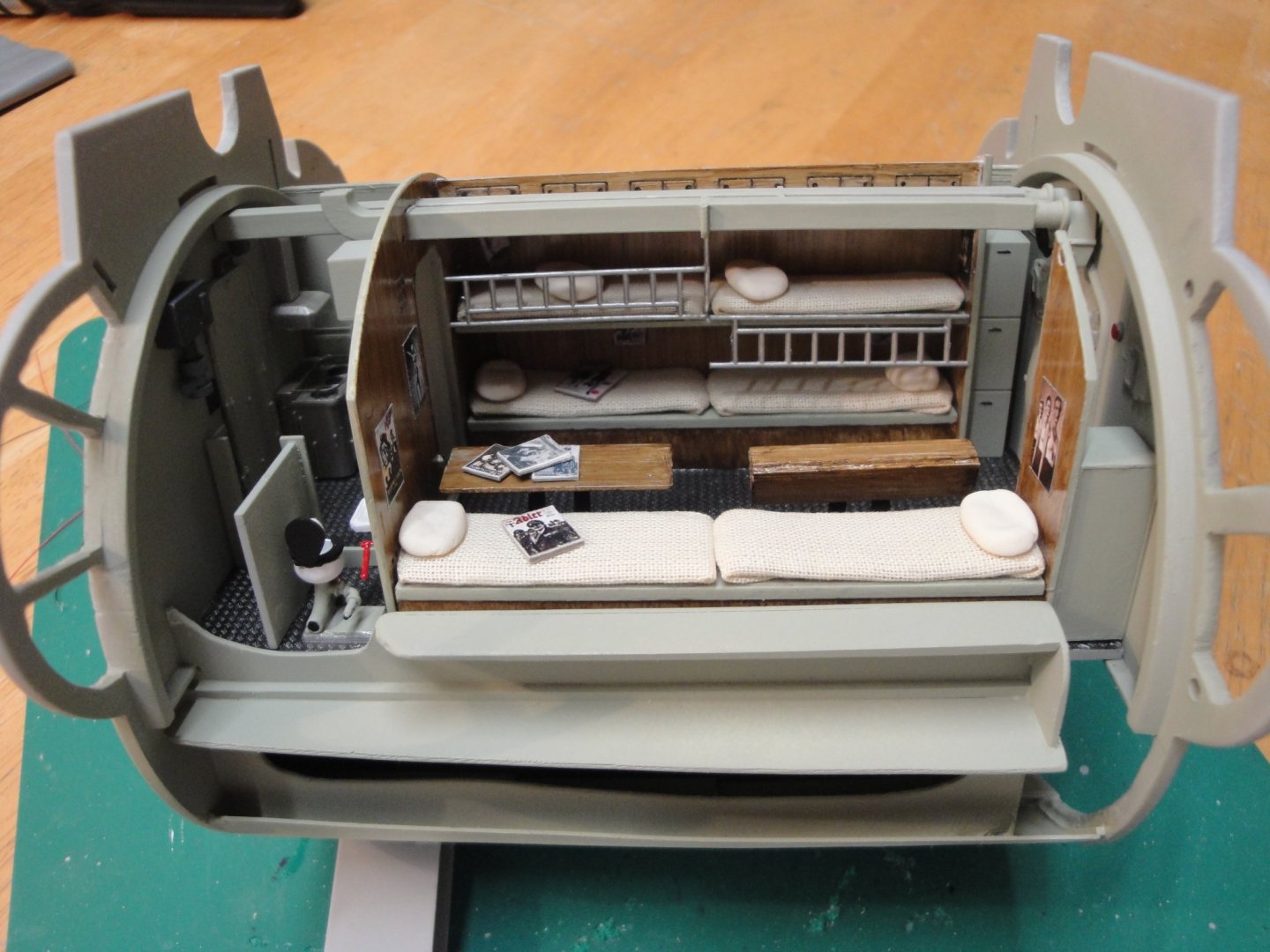
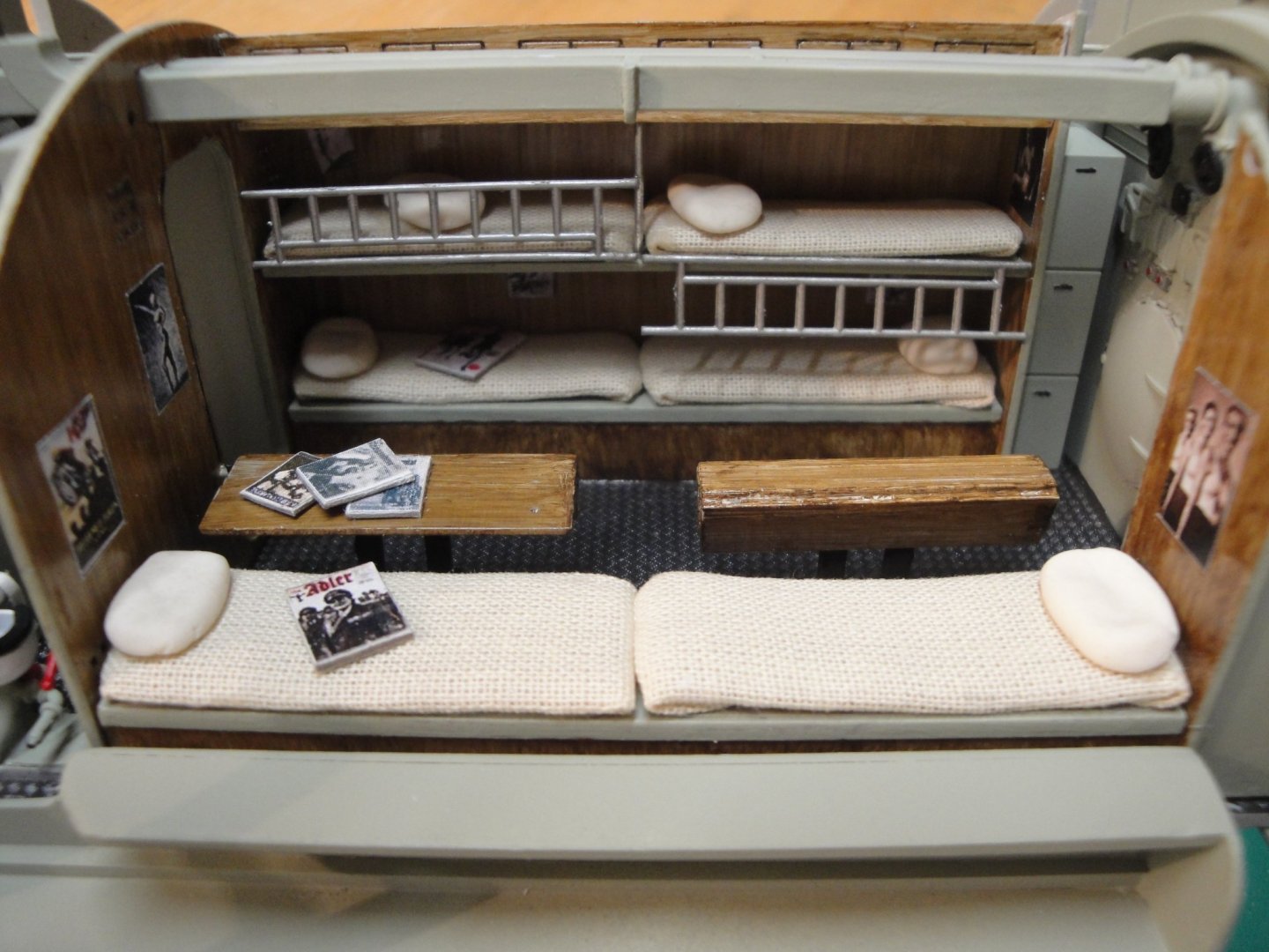
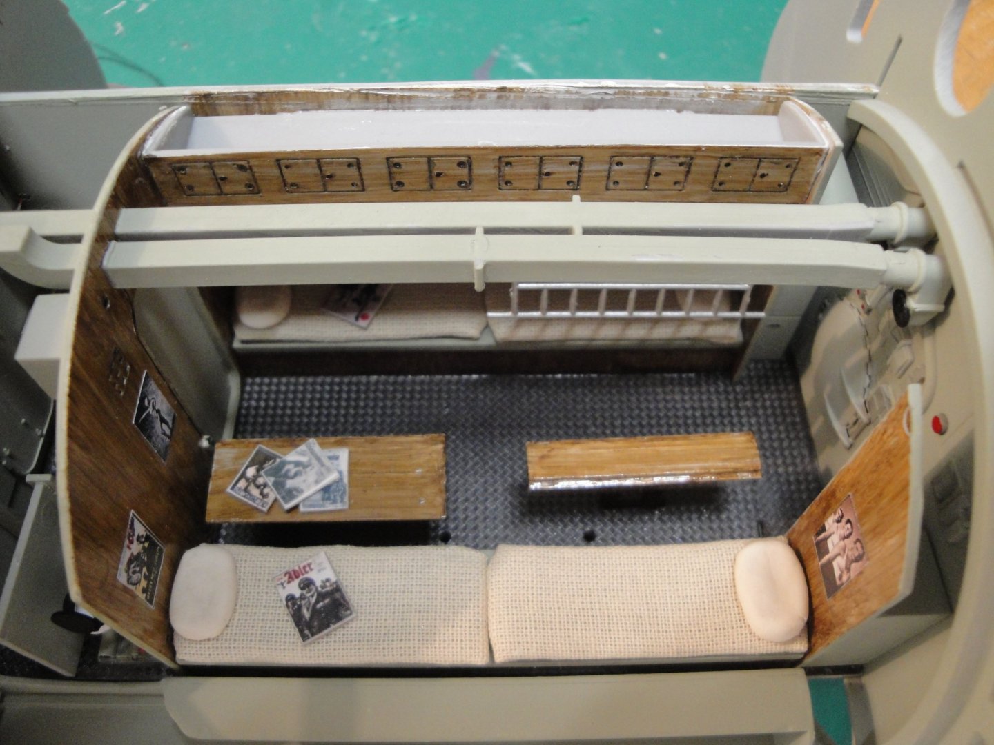
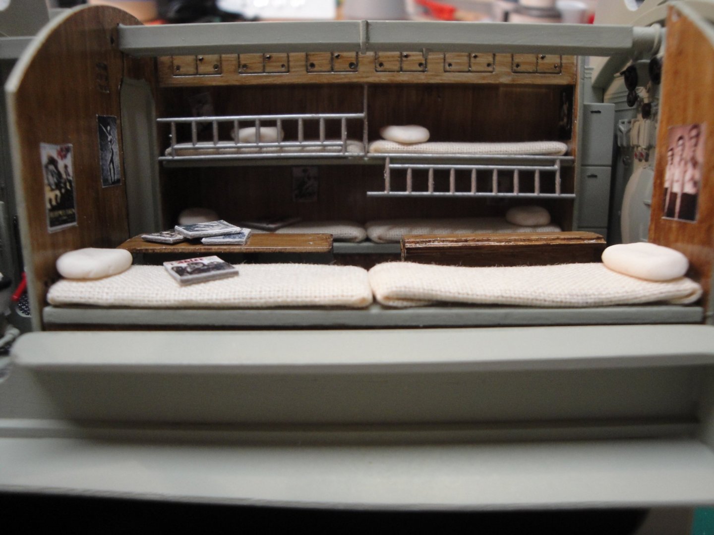
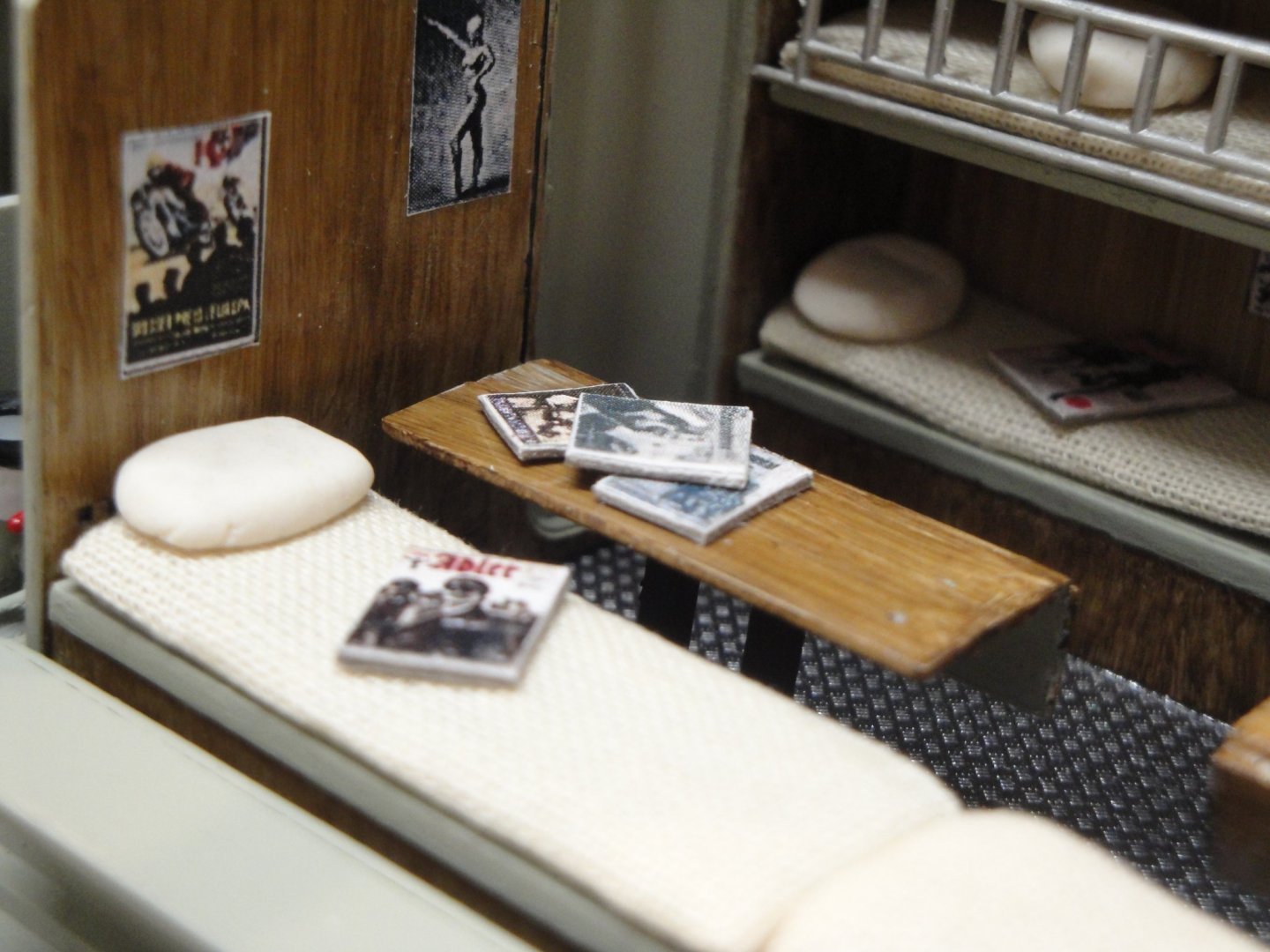
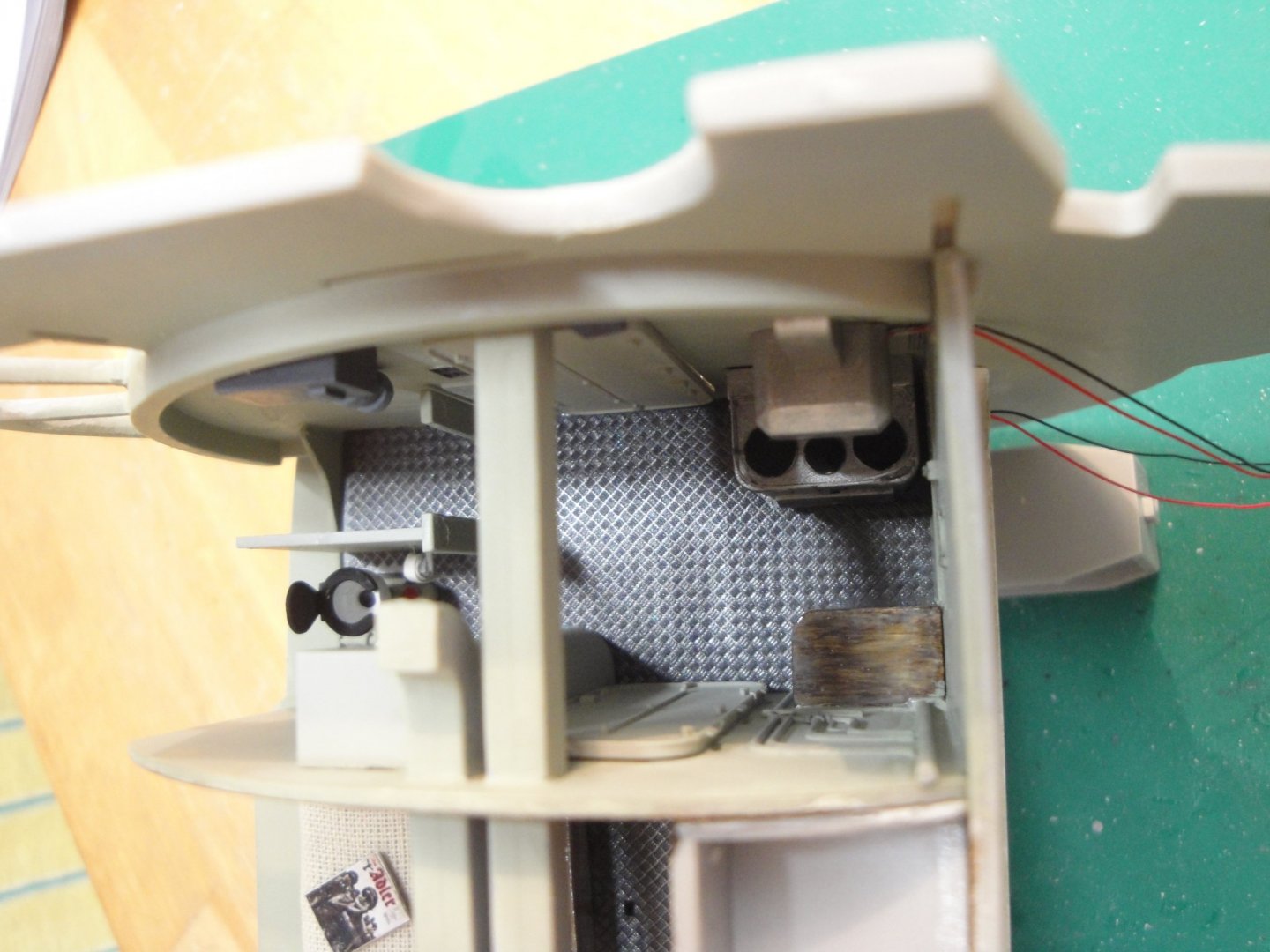
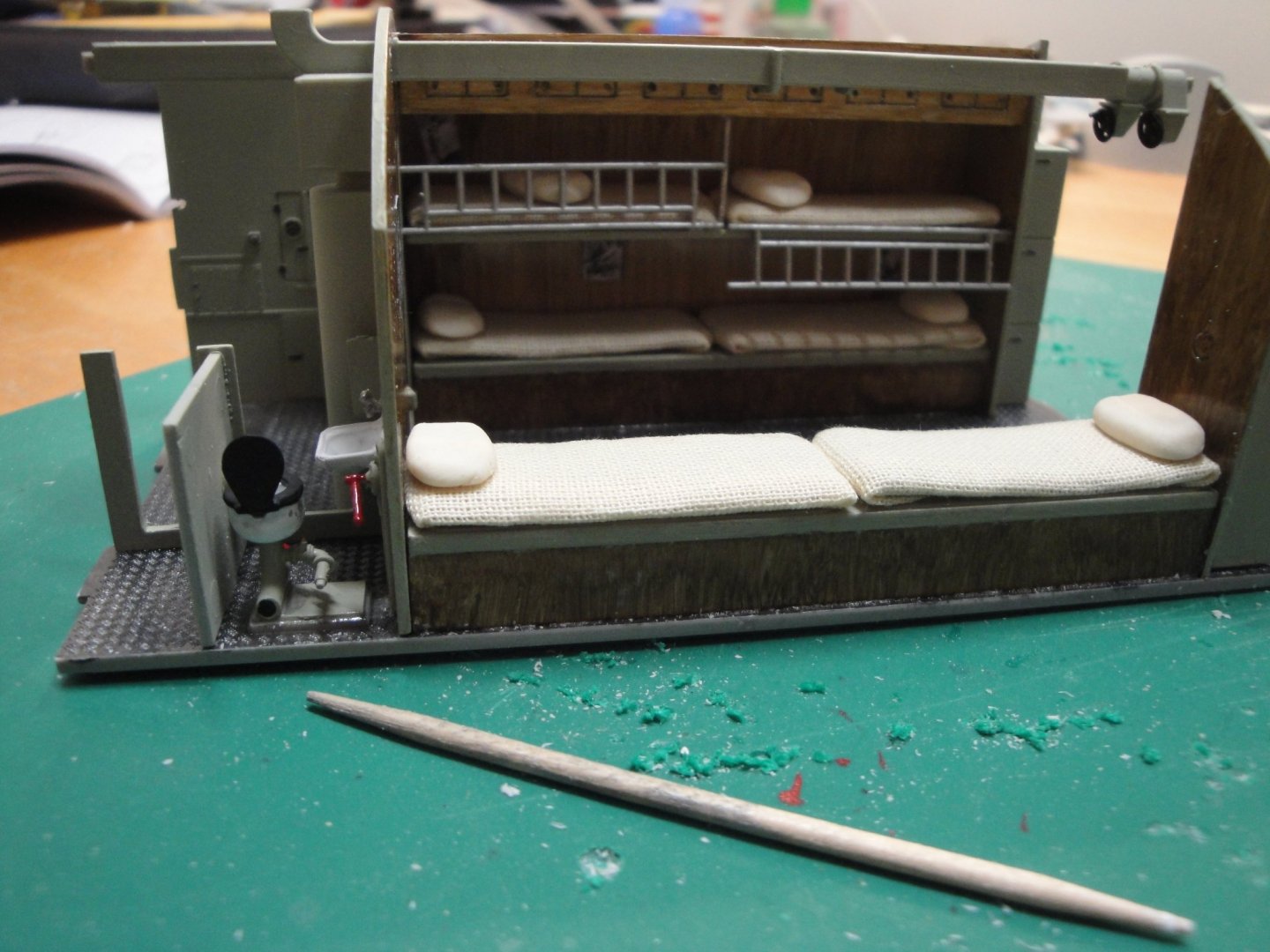
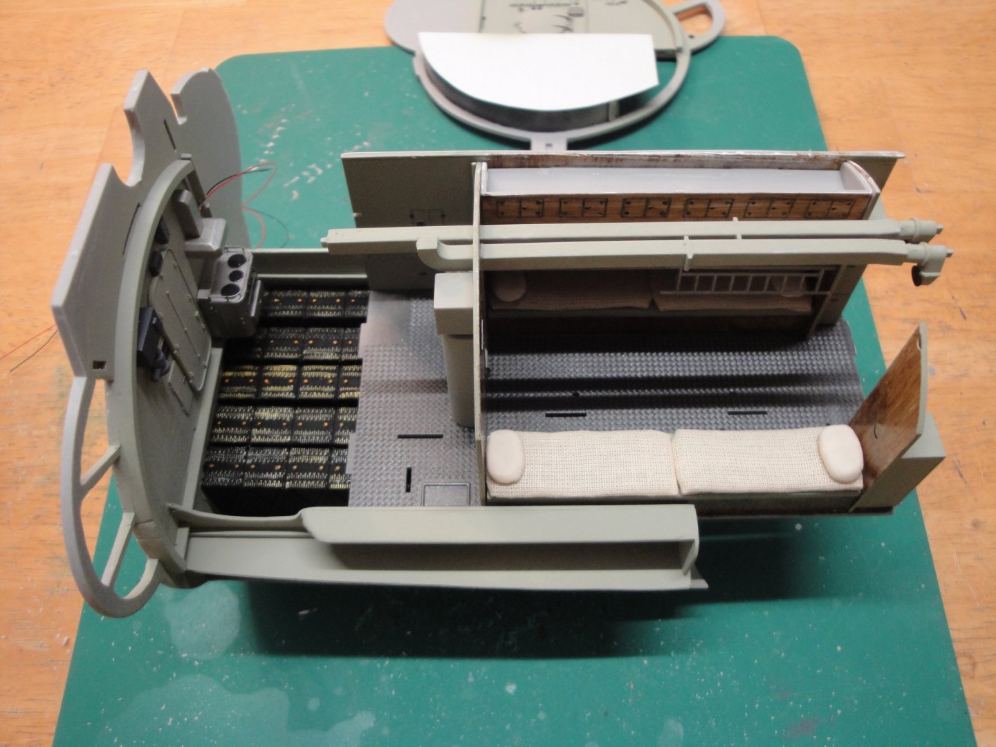
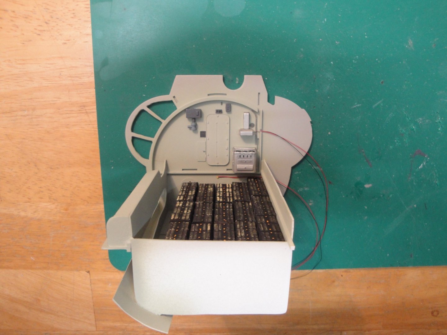
Module is almost completed. A few more details, the ceiling/pressure hull and it will be over. In the meantime, enjoy some shots: The fuel tank (below) surrounding the batteries room: The sleeping quarter, also used for eating and relaxing (as far as you can relax inside a submarine): Galley, pantry and toilet room: Lots of magazines (propaganda) and Nazis ideology posters on the walls: Magazines are made of a cover printed at scale and glued on a thin cardboard sheet. All covers are authentic Kriegsmarine and Adler publications from the early 40's. Girls are the Olympic champions of 1936, held in Berlin. Aerial view of the galley: I still have to solder some electrical wires, glue the ceiling and fill up the tank. Some painting on the outside and the main air hose to be added on top of the pressure hull, and the module will be ready to rest in the hull. Yves


- 760 replies
-
- 21
-
-
That is Trumpeter choice and reasoning. As someone mentioned it before, I suspect that these independent modules were designed by different groups and ended up with a different level of quality and details. I thought about it. The hard part is to find the perishables..... actually, I have a lot in my fridge right now 🙂 Honestly, I have a trail and need to order a couple of things. Yves
-
Very well done. Congratulations. I would place a couple of lines to tie the vessel to the pier. The illusion will then be complete. Yves
-
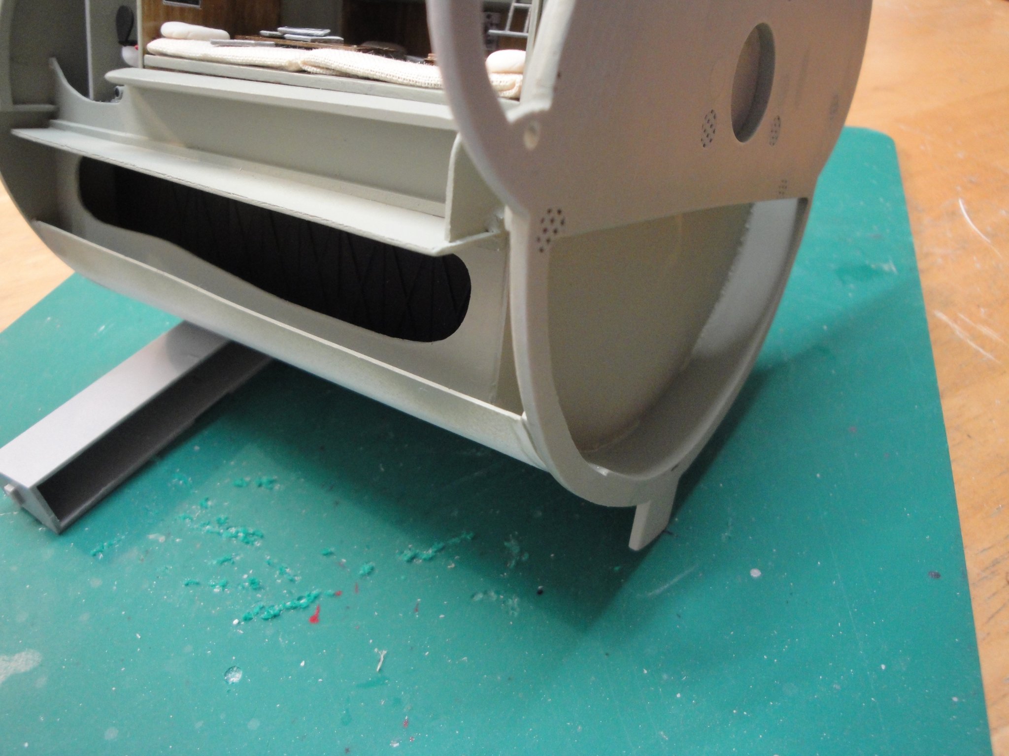
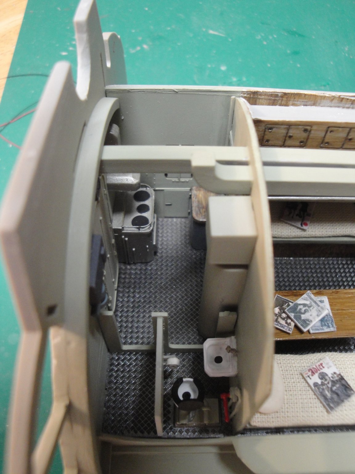
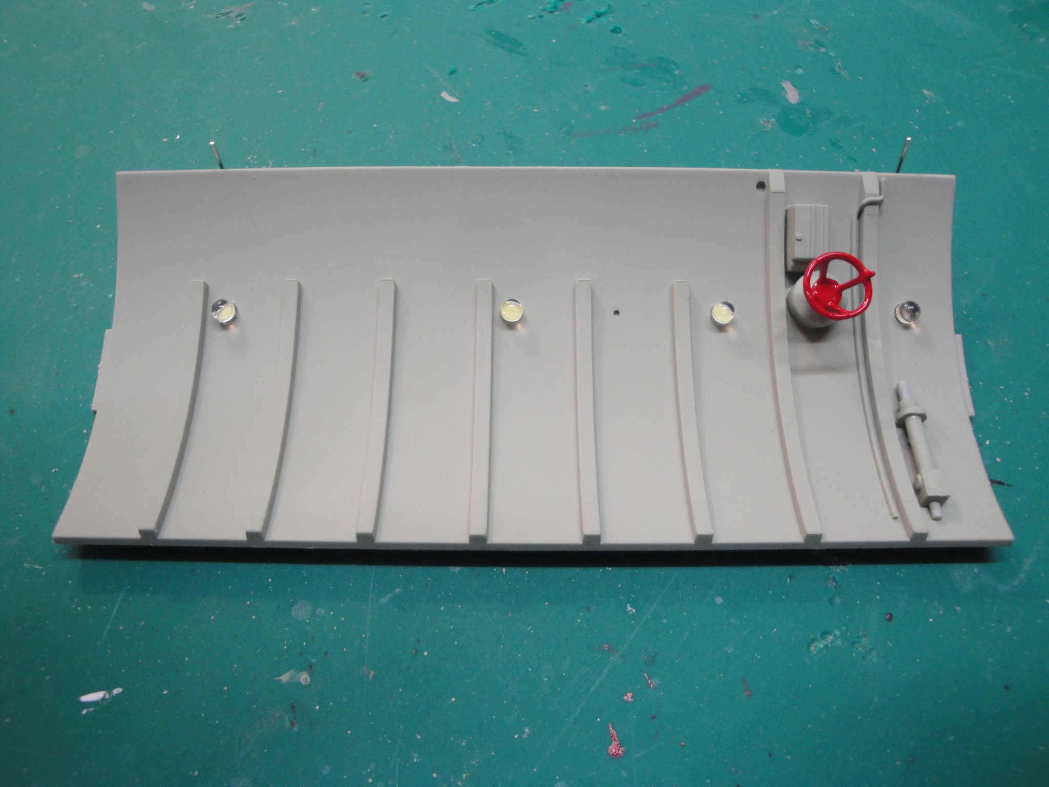
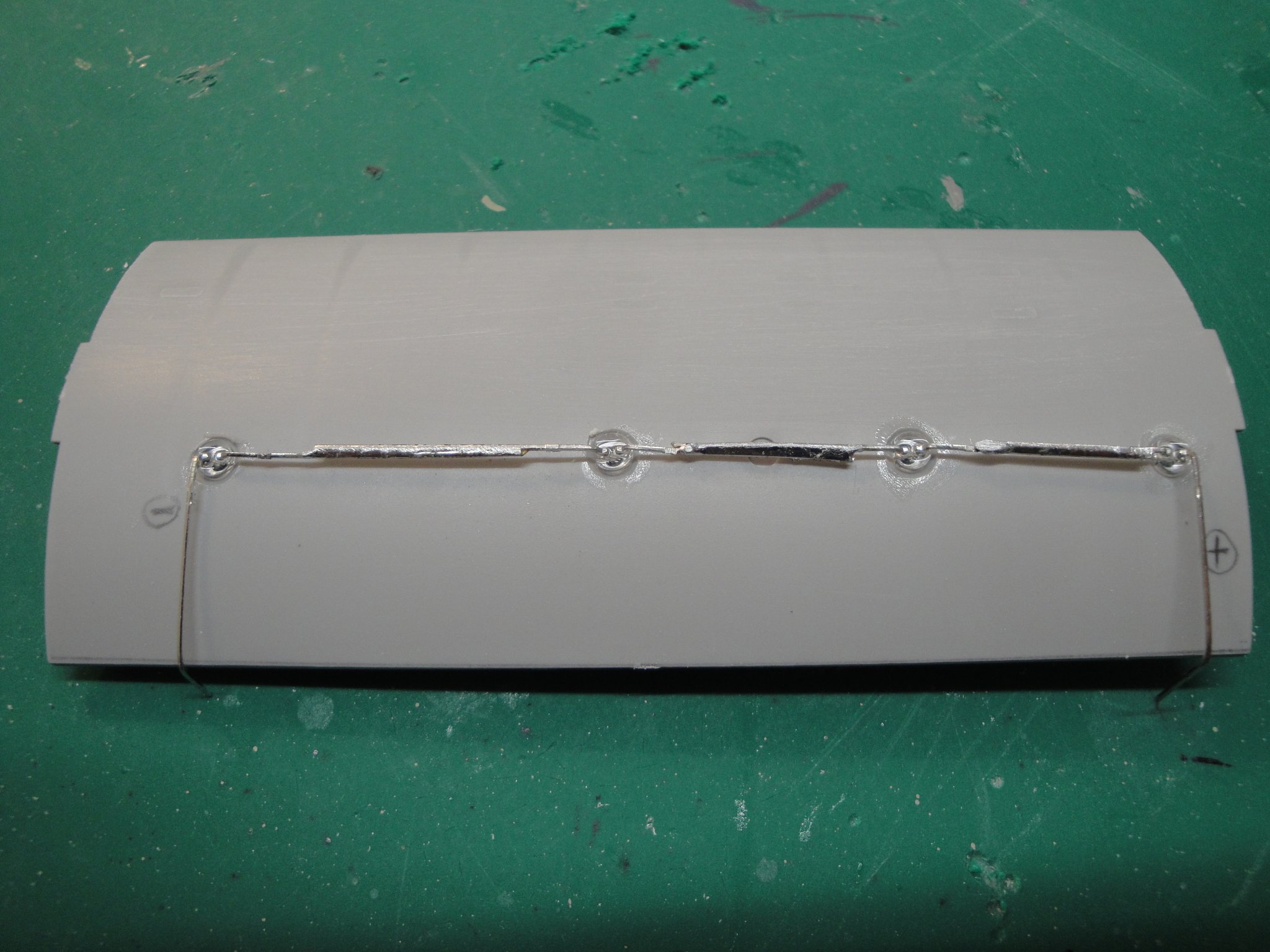
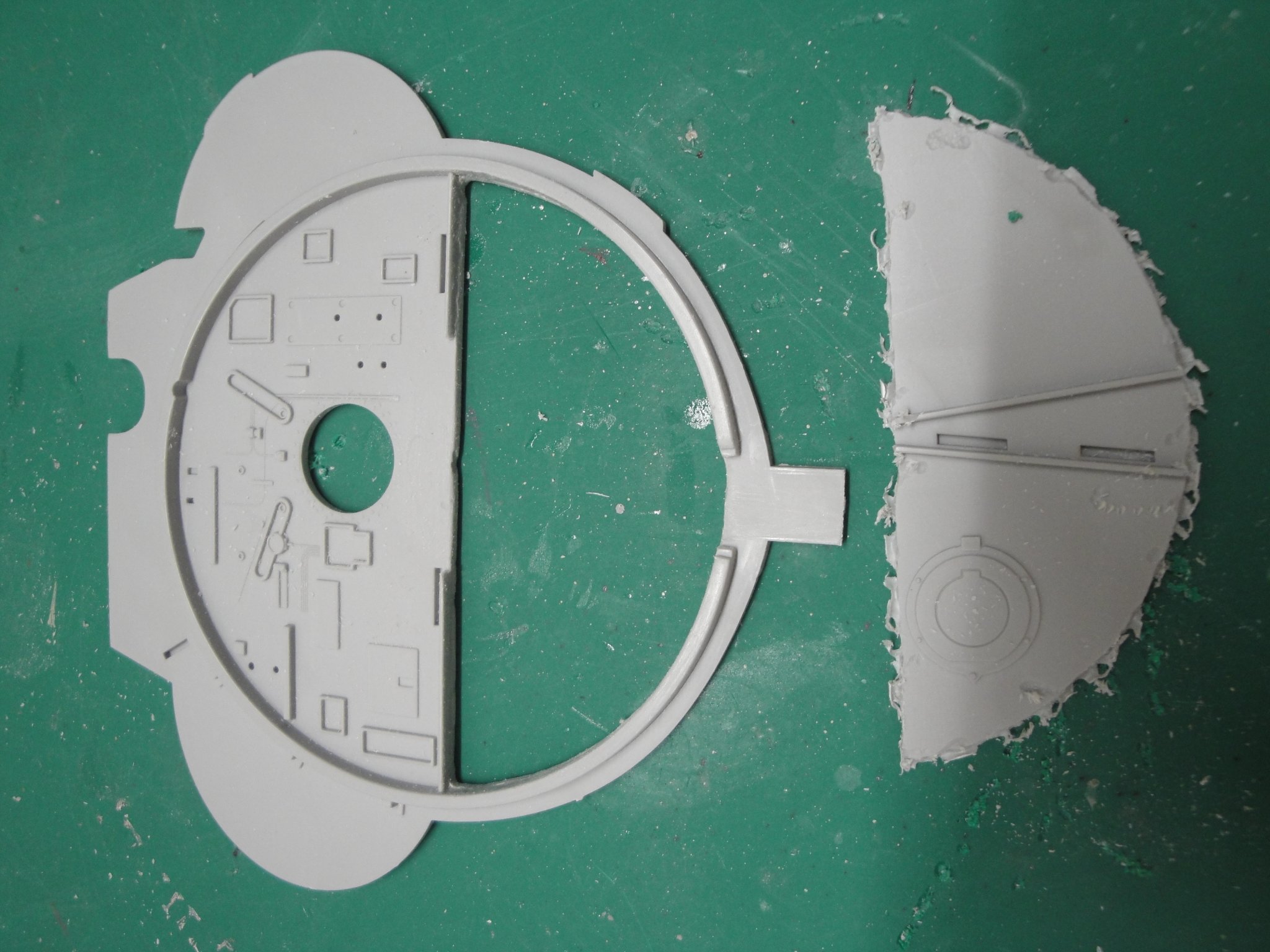
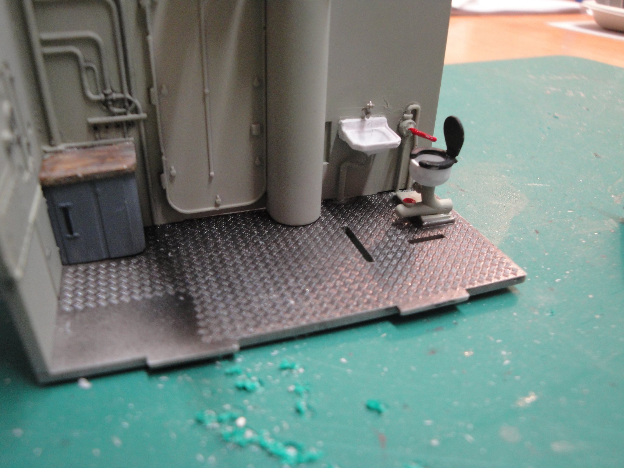
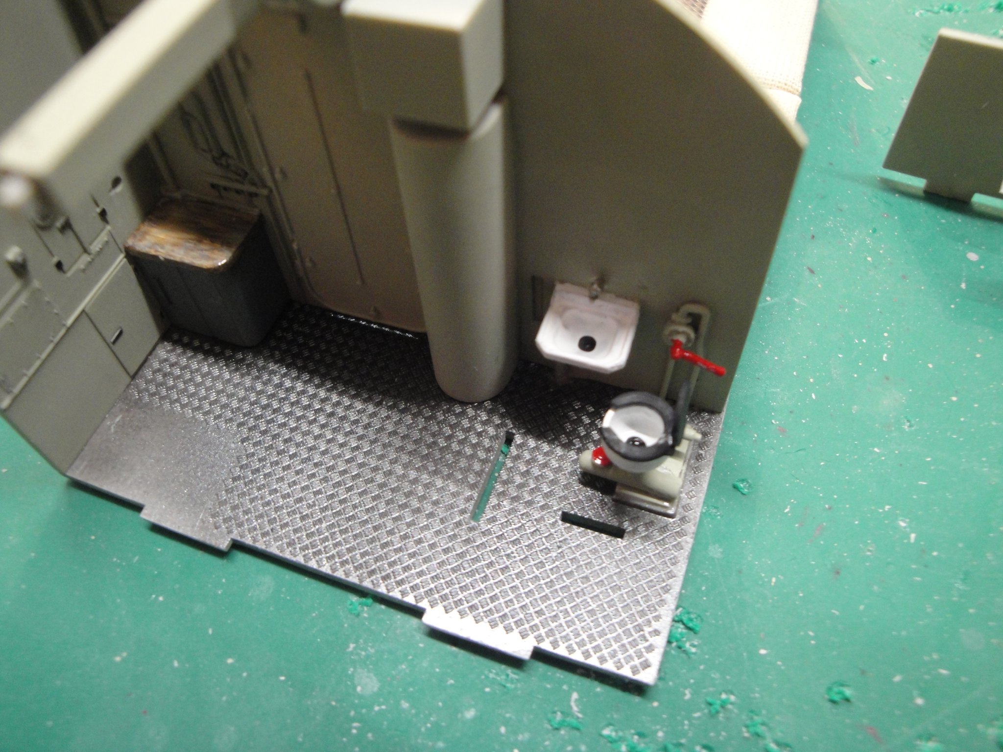
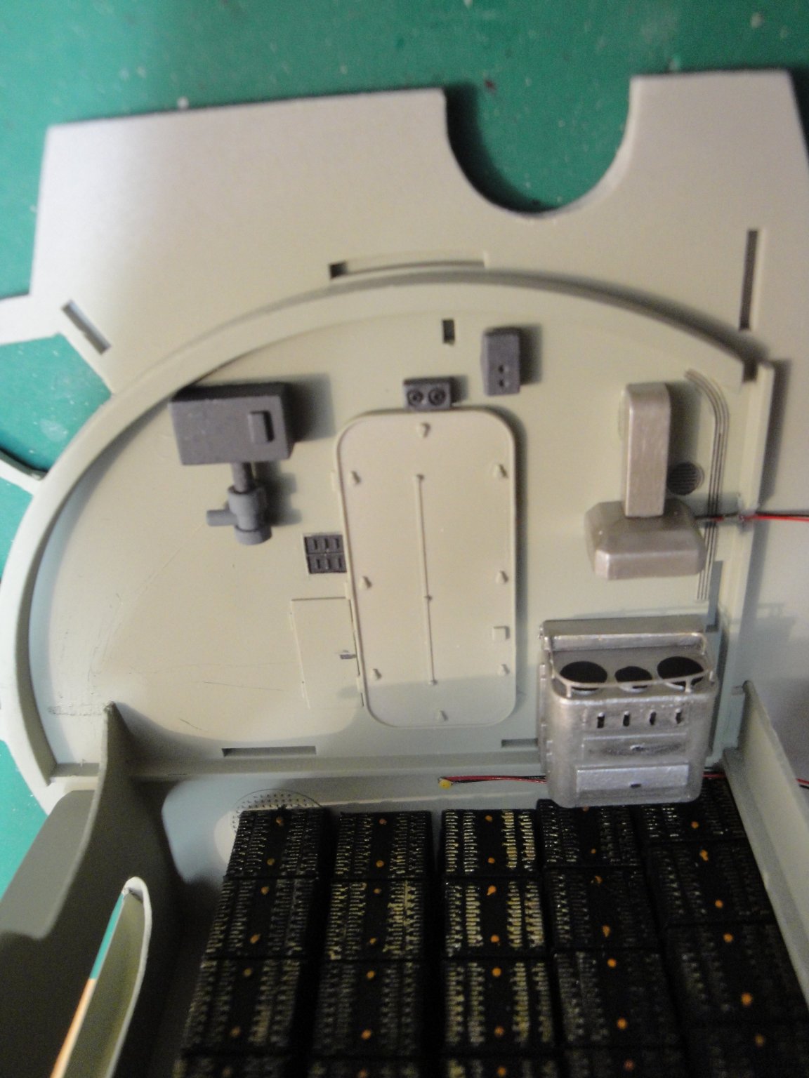
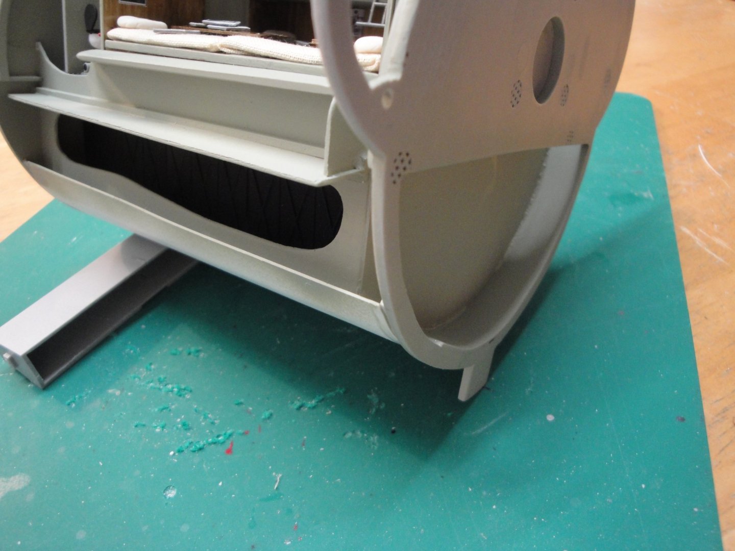
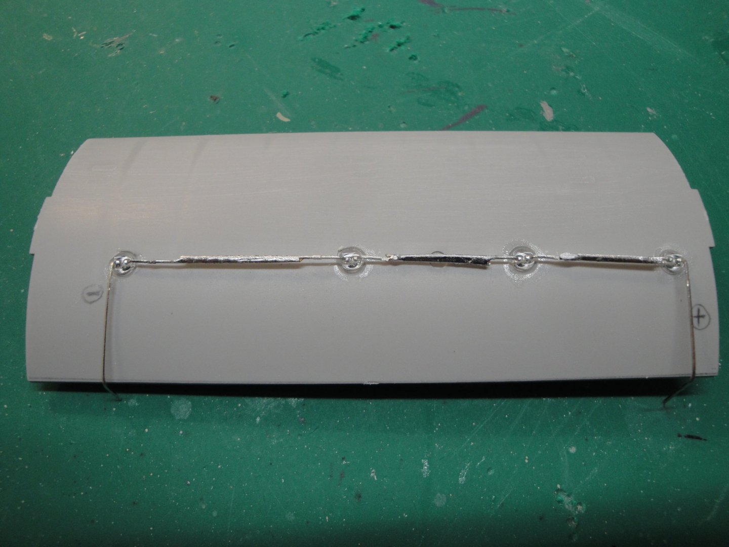
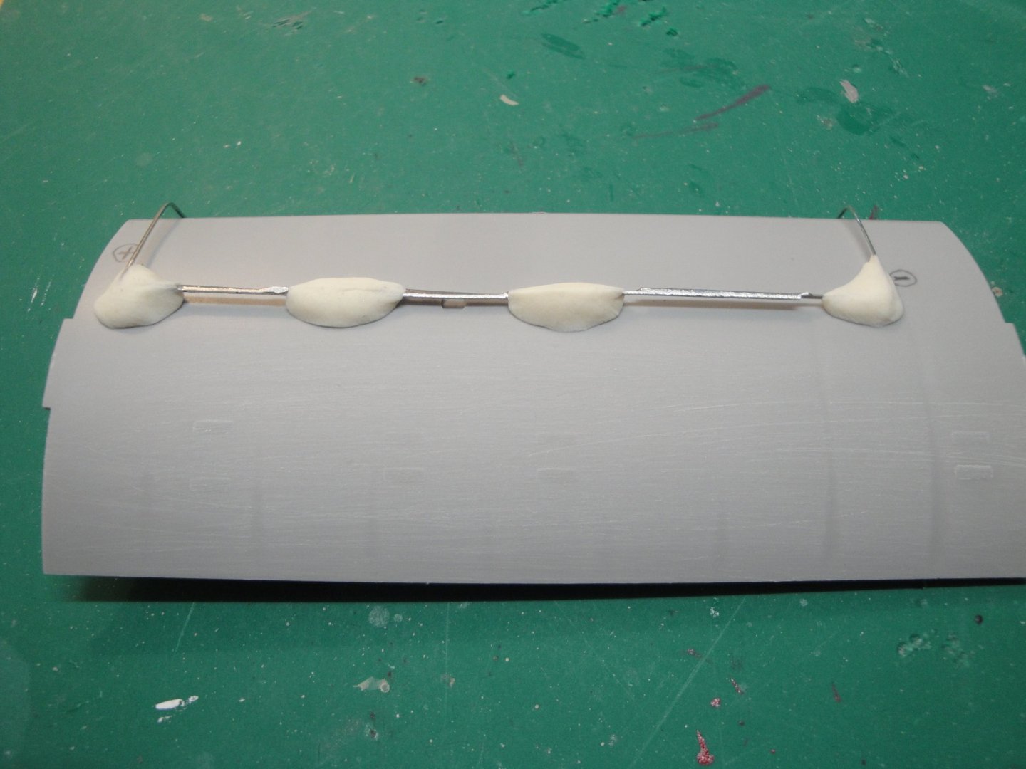
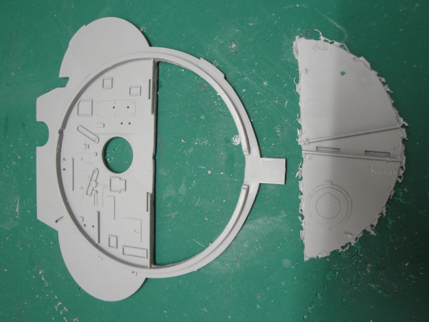
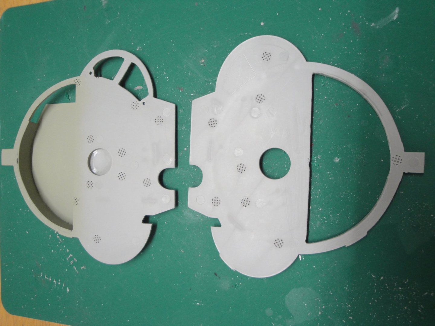
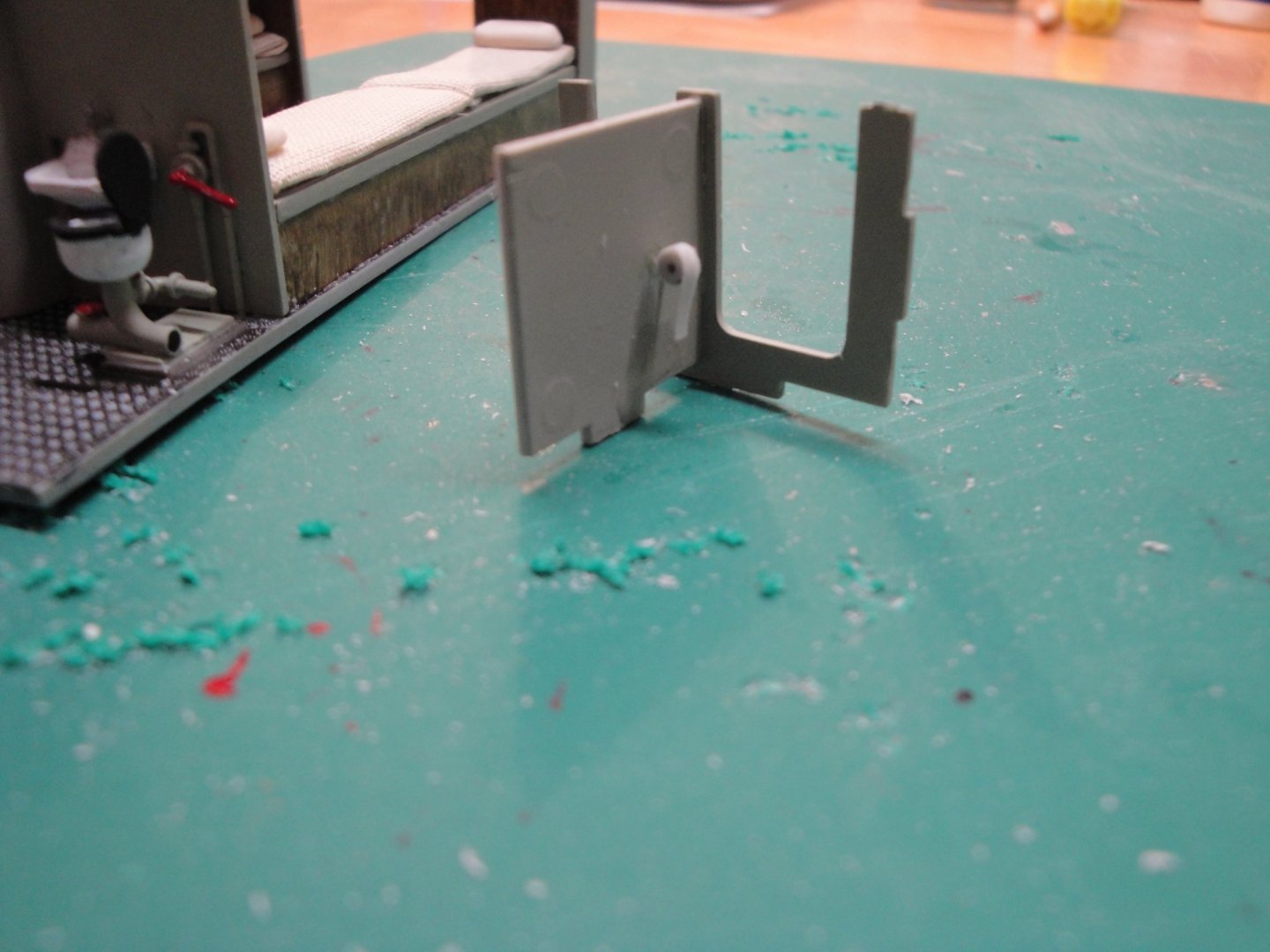
Installation of four white LEDs on the ceiling/pressure hull: The "Cook Hatch" has been improved with a large wheel (not in the kit). Wiring of the LEDs in series (4 x 3 volts = 12 Volts). Some putty blobs to prevent light leaks. Once painted, they should prevent any unpleasant light leaking outside of the pressure hull. All this will not be visible once the hull is closed. Also working on the bulkhead of the control room. Openings have to match: All this is to help represent the large rear fuel tank, located around the rear officer compartment and under the control room. Back to the sub-officer and kitchen compartment, Trumpeter screwed up royally by mixing up the toilet room and the pantry. Instead of the necessary appliances, Trumpeter is giving us a wooden box..... Very useful to dump a c...!!! I have built a small platform to install the second set of toilet bowl and sink (which is of course not provided in the original kit). They could have offered a second set to populate that very visible room..... But no! Let's not forget the toilet paper....apparently a very valuable (and rare) item, nowadays. View on the ducting bringing fresh air: Very soon, we will be closing the lid on the batteries room: Hope you enjoy. Yves


- 760 replies
-
- 20
-
-
Very nice beginning. Looking forward to seeing more. Yves
-
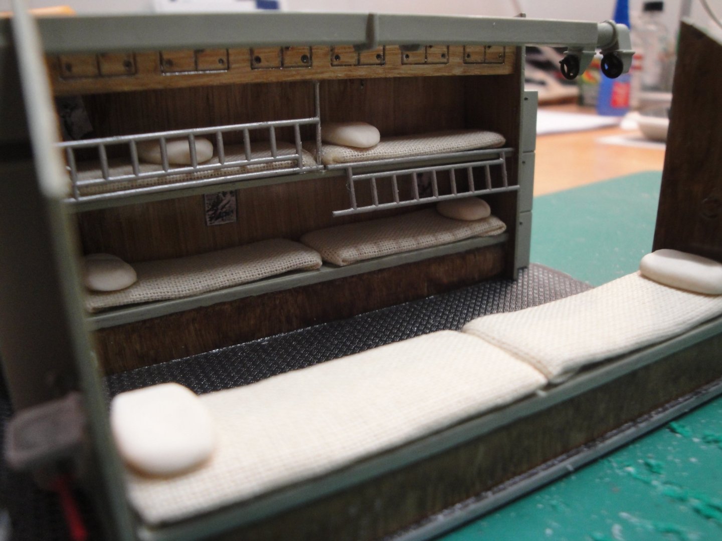
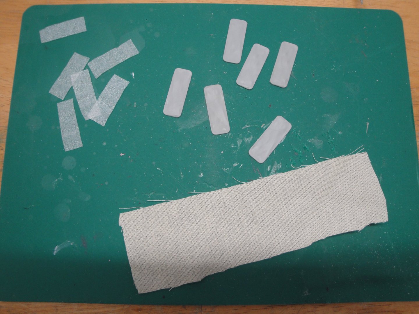
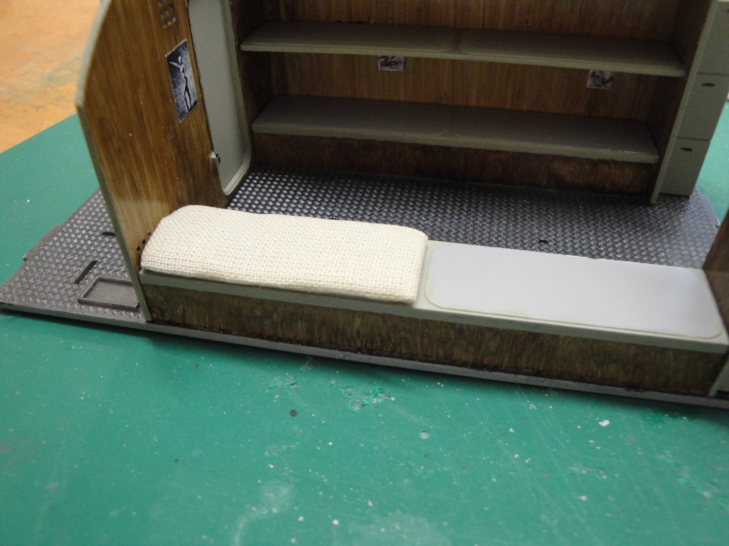
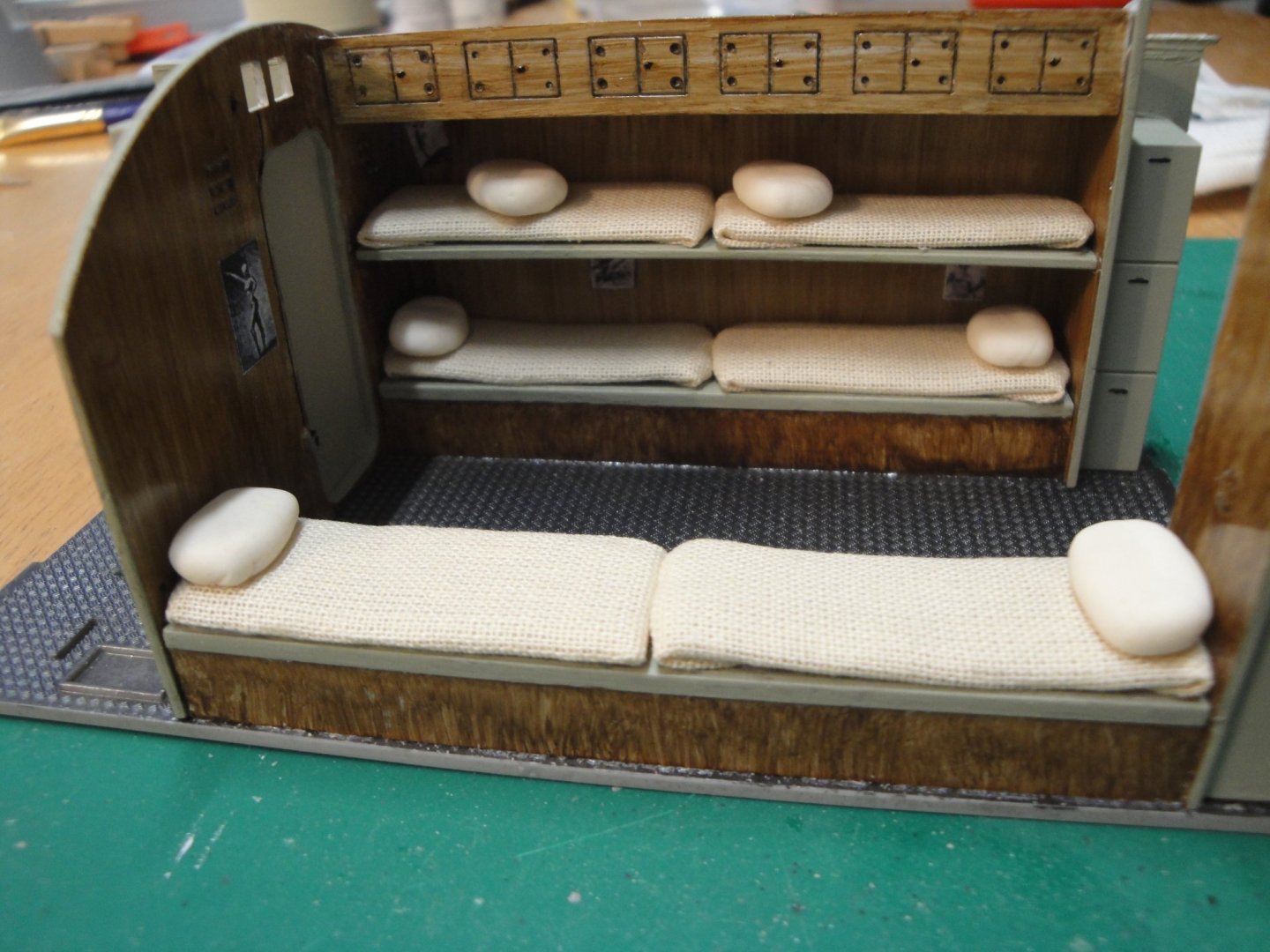
Just finished building the six mattresses. These are made with the original Trumpeter part, a layer of thin foam and a piece to wrap the whole thing: One bed completed.... five more to go: Et voila. Pillows are made with white putty. These will be formed more precisely and then lightly stained for more realism, once dry. Yves
- 760 replies
-
- 20
-
-
Wow, Wow, Wow!!! This is becoming serious! Such attention to details, such realism. I suspect your Build log will boost sales of Chaperon at Model Shipways. Yves
- 133 replies
-
- 6
-
-
- chaperon
- model shipways
- (and 2 more)
-
Your build log is truly inspirational. You are putting together a little marvel. Yves
-
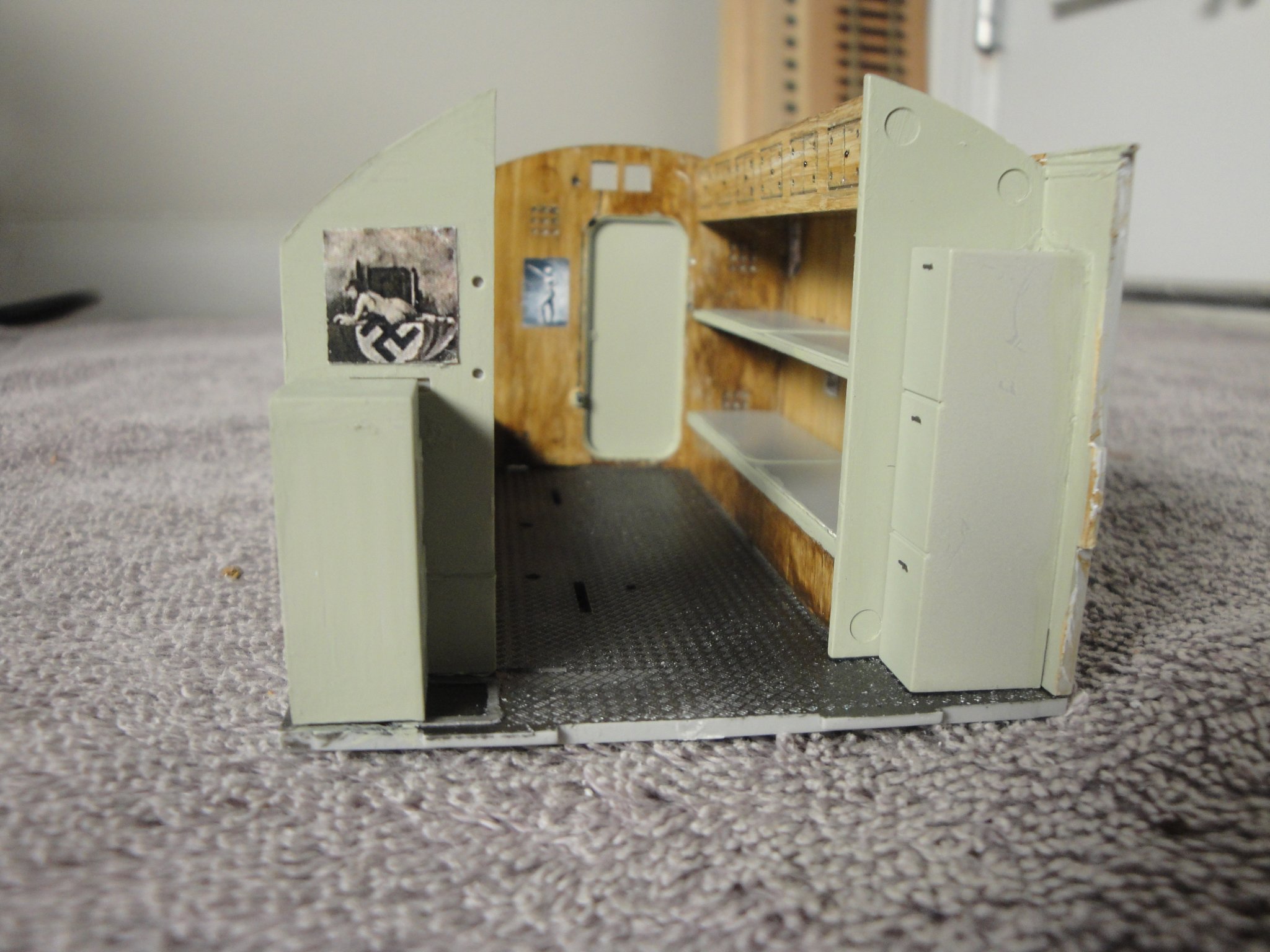
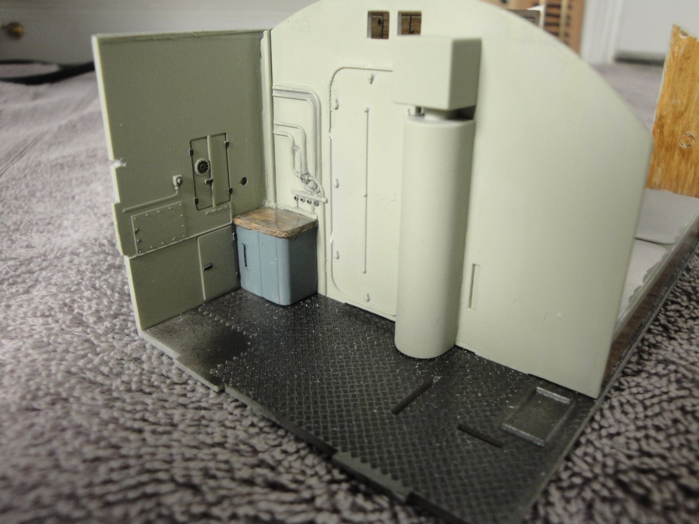
Thank you Bob, your compliments are very well received. Small progress on the living quarters and kitchen. That view will most likely be no longer visible once the front bulkhead is in place. So enjoy that nice genuine poster, sitting on top of the auxiliary fridge: Some of these parts are not provided in the kit, but taken from the extra set of parts I have. The kitchen sink (below). The sink was equipped with a small basin and four taps: two for cold-warm/fresh water for cooking or drinking and two for cold-warm/salt water for washing the dishes. When not in use, the sink was covered with a large wooden board (depicted here), used as the only plane of work for cooking. The size of that board was 83 cm x 45 cm. It is no wonder the cook was revered more than the officers, in most cases. On the left wall, a cold storage was used as a fridge, and below another storage area was available as well. Trumpeter did not represent the faucets in detail as well as the large cock located above the sink because it is not visible once the module is assembled. Right above the kitchen is also a hatch (Kitchen hatch or cook hatch) that we will see when we put together the roof/pressure-hull element. That hatch was used to pass small food supplies. Yves

- 760 replies
-
- 20
-
-
Bob, this is so realistic, it almost hurts the eyes. Actually, it is beyond realistic... It allows you in one glance to encompass what human vision could not grab at once. Yves
-
That pre-former plate is really clever. Very very smart to offer this kind of tool in the kit. Yves
- 77 replies
-
- 8
-
-
- morel
- master korabel
- (and 1 more)
-
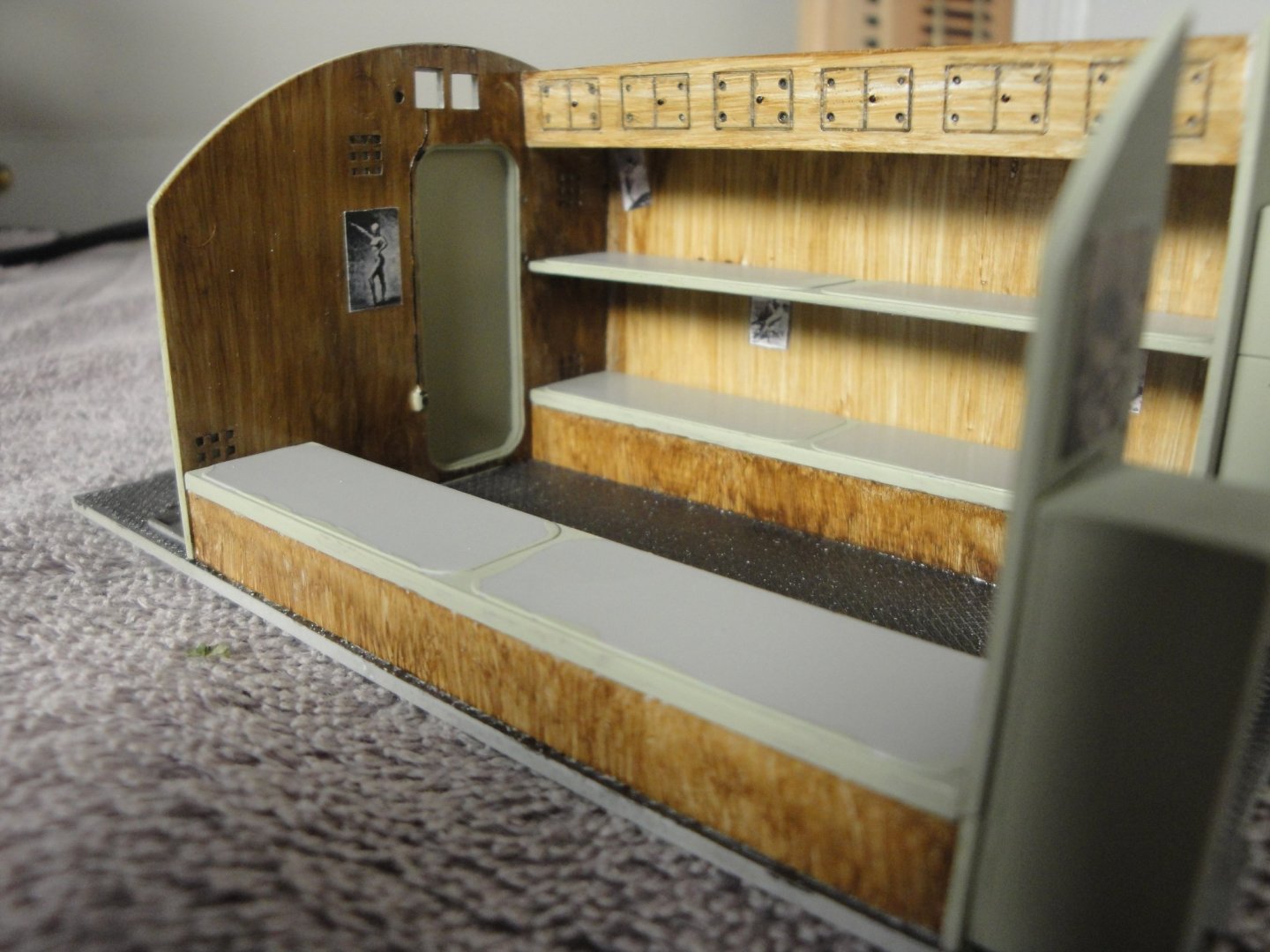
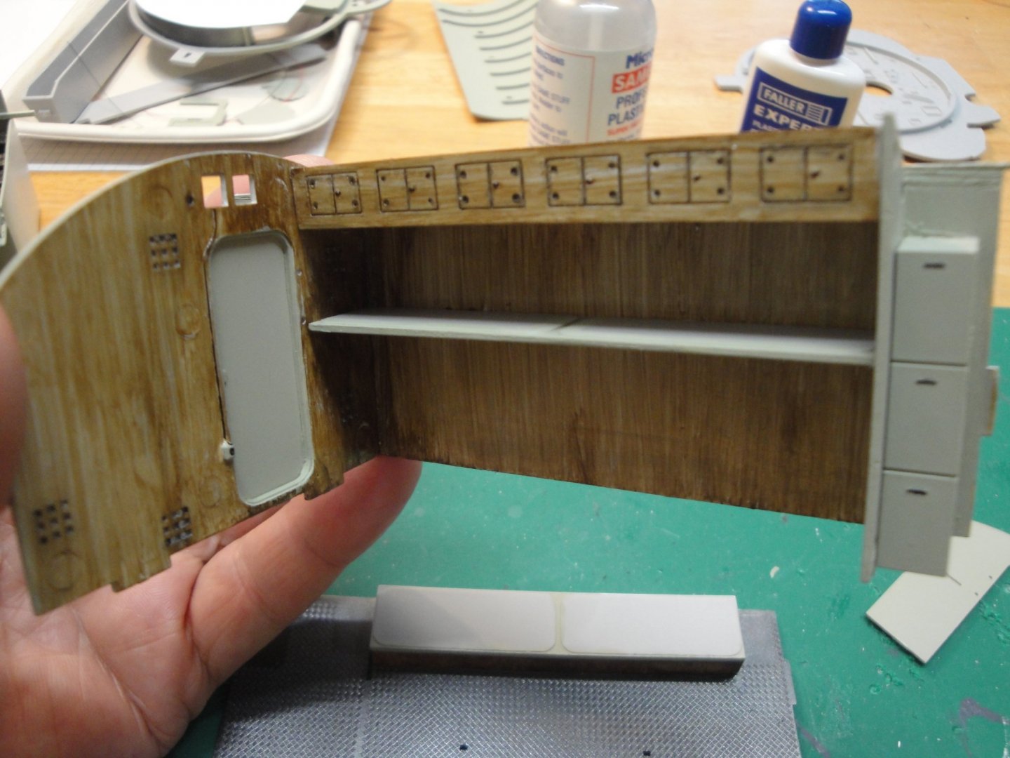
I am doing some woodwork, building partitions, bed bunks and remodeling my kitchen: Lots of saw dust around here..... Yves

- 760 replies
-
- 16
-
-
Beautiful construction. I will be following with interest as Syren is one of my favorite ship. Yves
-
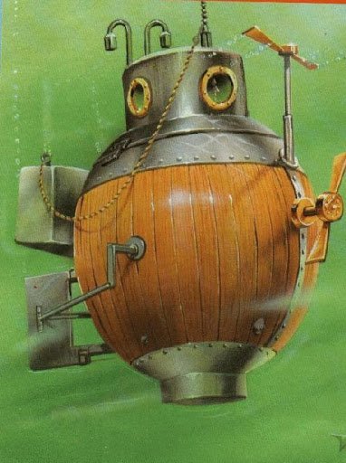
I suppose, this submersible is more or less the equivalent of the American Turtle: Yves
- 77 replies
-
- 5
-
-
- morel
- master korabel
- (and 1 more)
-
A few details for tonight. The rear bulkhead is pretty much completed. I still have to paint the outside of the pressure hull: The stove to prepare food for 44 people, three times a day ..... I decided to close the door to the diesel engines room, to allow a better view of the Galley. The noise was preventing the cook to do his job, anyway... Yves

- 760 replies
-
- 12
-