HOLIDAY DONATION DRIVE - SUPPORT MSW - DO YOUR PART TO KEEP THIS GREAT FORUM GOING! (83 donations so far out of 49,000 members - C'mon guys!)
×


yvesvidal
-
Posts
3,607 -
Joined
-
Last visited
Content Type
Profiles
Forums
Gallery
Events
Everything posted by yvesvidal
-
 WOW!!! This is coming along nicely. Very realistic model. Yves
- 337 replies
-
- 4
-

-
- finished
- mountfleet models
- (and 1 more)
-
Very interesting and lovely boat. Billing Boats has been creating quite a few kits with this half-hulls technique. It works really well. Yves
- 83 replies
-
- 2
-
-
- finished
- billing boats
- (and 1 more)
-
I am impressed at the quality of your painting and the vast collection of jars that you have. Truly impressive. What are the ones in the center, saying Acrylic on the glass? Yves
-
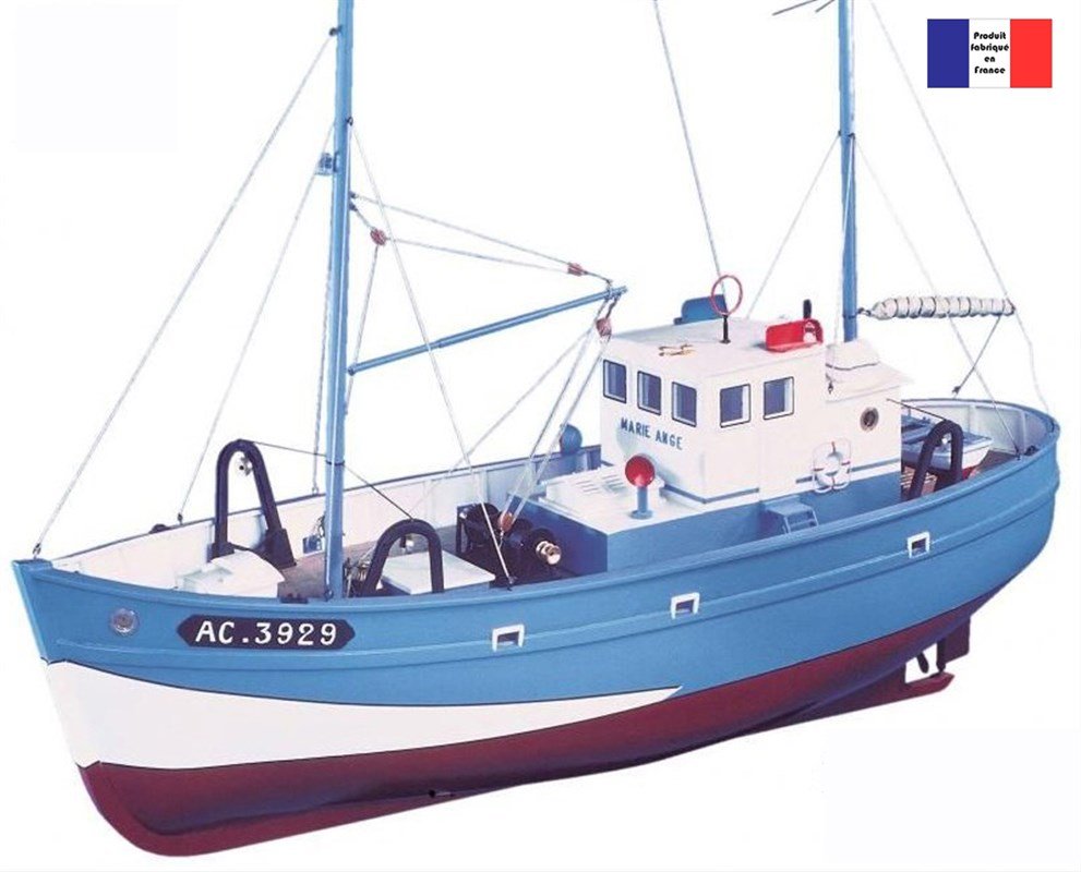
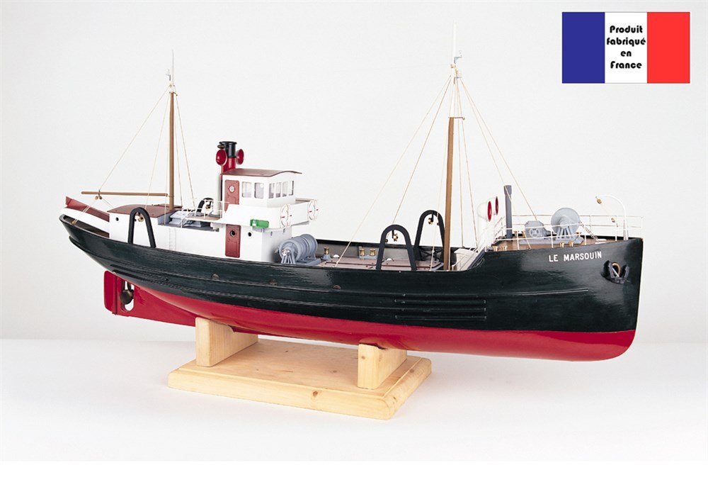
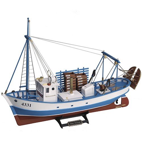
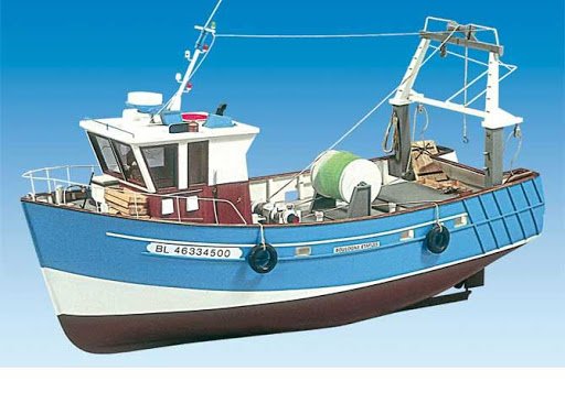
I agree that finding a good quality kit is sometimes hard to do. There are so many of these fishing vessels around the Mediterranean Sea and the Normandy and Brittany shores, that you cannot go wrong if you decide to customize them a little bit. I know that Chris Watton is usually releasing very high quality boats, but the ones shown on your link are no-where to be found on the French coast lines. What you are building is "the" typical French fishing vessel. I have seen a lot of these when I was a kid and they are still used a lot nowadays. Artesiana Latina and Constructo released similar vessels (My brother built a couple of them) but AL is now out of business and Constructo's quality is not exactly what you want.... Below are a few examples, but honestly, the Chalutier you picked up is probably the nicest one: Marie-Ange by New Cap Maquettes Le Marsouin, one of my favorite but almost impossible to find. The Mare-Nostrum by AL....toy like when compared to your model. The Boulogne by Billing Boats. There are many more and it would take an entire thread to cover them all. I hope you do not feel like I hijacked your thread. Let em know. Thanks Yves
-
Your trawler is coming along very nicely. I hope you keep this one. Yves
- 337 replies
-
- 4
-
-
- finished
- mountfleet models
- (and 1 more)
-
I love your serving machine made with Meccano/Erector parts. It brings back a lot of fond memories. Yves
- 183 replies
-
- 11
-
-
Beautiful hull. I like these French fishing boats. Thanks for building one of them. Yves
-
Very realistic. Yves
-
I like your research efforts to improve on the Trumpeter kit. Sounds familiar to me.... ;-) Yves
-
Superb presentation of your beautiful gondola model. The black color of the base, depicts quite well the dark waters of Venice at night. Yves
-
Here is an excerpts of the U-Boot Manual, regarding Fresh, Grey/Wash and Salted waters: 1) Sea water installation. To provide sea water collection in the galley, there is a branch off the cooling water manifold in the diesel engine room, which leads to the valve and a tap in the wash sink. The warm sea water installation branches off from cooling water head tank in the conning tower casing and leads to the wash basins in both W.C.s and to the wash sink in the galley. The discharge line of the auxiliary drain and trim pump branches off to the deck wash line. A shower head can be connected to this line, attached to the net protector, and stowed again after usage. 2) Wash water installation. Wash water is stored in the following tanks: 1 wash water tank (listening room) 1 wash water daily supply tank (aft W.C.) As reserve tanks there are: Torpedo compensating tank 1 Torpedo compensating tank 2 Wash water tank and wash water daily supply tank are connected to the fresh water filling and extracting line. Tanks are filled through the intake at the upper deck. The hand fresh water pump is used for filling the wash water daily supply tank from the wash water tank. A hand wash water pump provided in the forward W.C., to which a suction line can be switched by the selector cock to the wash water tank or to torpedo compensating tank 2. Extracting the wash water from torpedo compensating tank 1 takes place by means of compressed air. 3) Fresh water installation. Fresh water is stored in 3 tanks (3.870 m³) situated in: Fresh water tank 1: Galley, port, under the floor Fresh water tank 2: Control room, port Fresh water tank 3: Officers room, stb. The fresh water tanks are connected to the filling and extracting line through the fresh water selector cock. The line leads through the hull valve at the upper deck and inside the hull branches off to the emergency drain connection. The hand fresh water pump in the galley takes suction from selected tank and discharges through the control valve either directly to the tap in wash sink or through the filter. The water supplied by the distilling unit in the control room is collected in the distillate tank and is moved through the control valve either directly or through the filter to fresh water tank 1 in the galley. All fresh and wash water tanks have sounding pipes and dip sticks.
-
Impressive. Some of the sounds are obnoxious, but I understand the excitement that such a model can create on a lake, surrounded by children. Yves
-
Beautiful model, exquisitely detailed and fantastic professional pictures. I had to save these two pictures in my personal folder. Way too nice. If you are too busy and eager to go back to ships building, I would not mind finishing that 1/32 scale Sleeping Car from the Orient Express that you never completed. Just saying.... 😉 Yves
-
So, half of the ship will be planked and the other half will show your fantastic work. I am amazed every time I look at your craftsmanship. Yves
-
Was it really invented or simply reverse engineered from outer terrestrial technologies? Yves
- 27 replies
-
- 1
-
-
- queen frederica
- cruise ship
- (and 3 more)
-
How about going with brass tube for the mast, instead and using stretchable wires (rubber)? Yves
- 337 replies
-
- 4
-
-
- finished
- mountfleet models
- (and 1 more)
-
The gray water was used to flush the toilets. The kitchen was equipped with two faucets, one with fresh water for cooking and drinking and another one with salt water for washing dishes and maintenance. Besides this, I am not too sure and would have to research it. If I find something, I'll post it here. Yves
-
Kevin, How about soaking the ropes in warm water for a little while, placing them under tension to the best of your abilities and then let them dry. A dry rope is always shorter than a wet rope. Old barometric devices were based on that principle. Yves
- 337 replies
-
- 3
-
-
- finished
- mountfleet models
- (and 1 more)
-
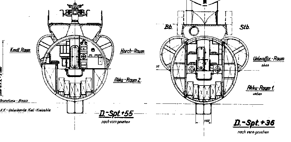
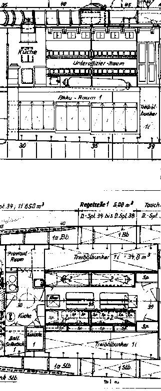
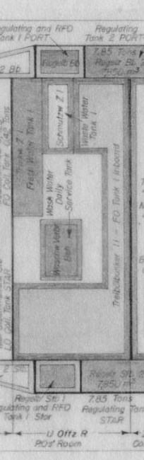
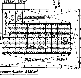
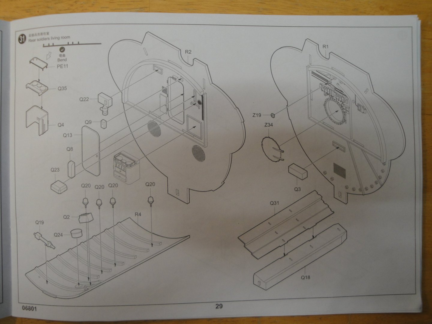
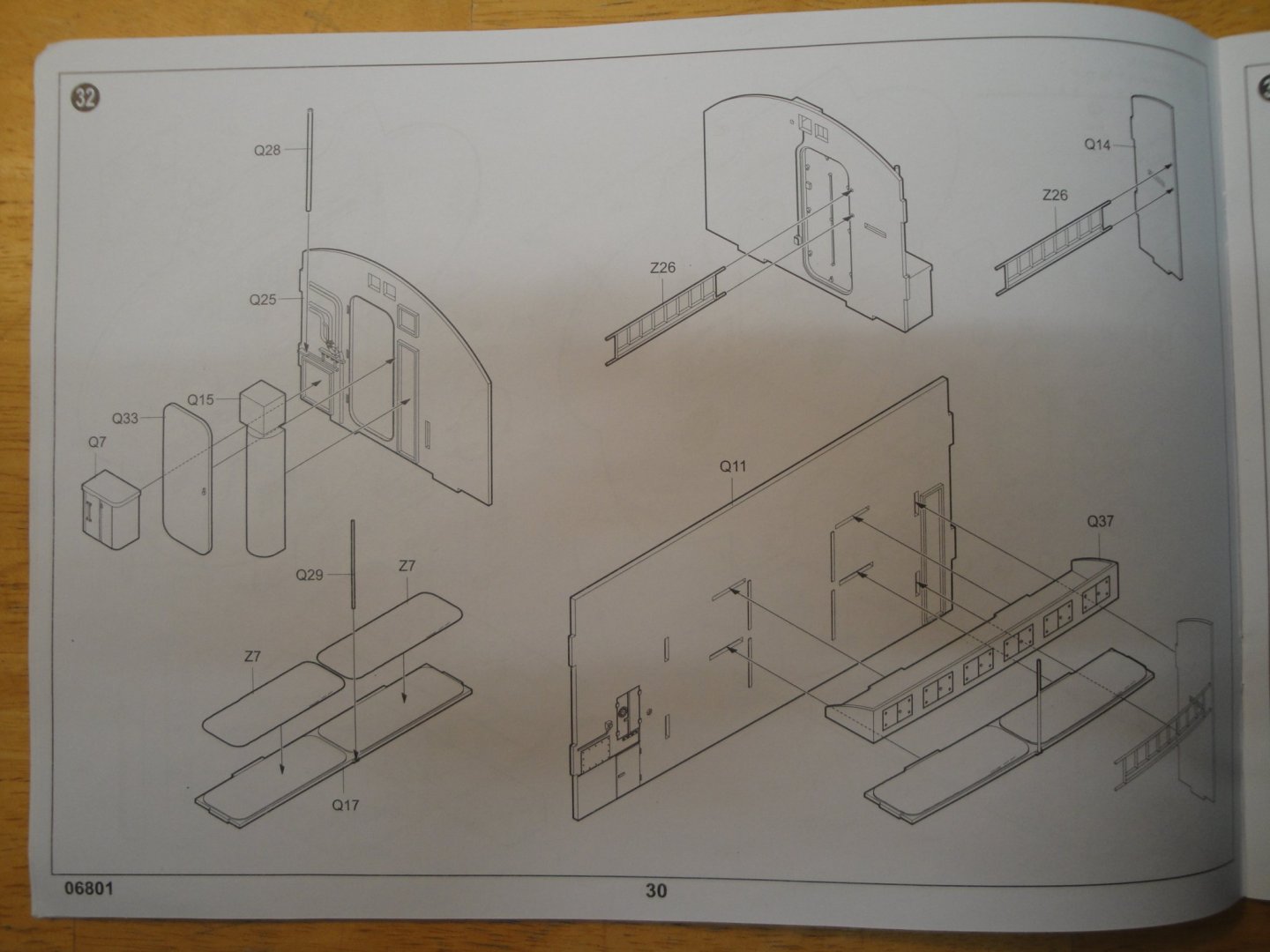
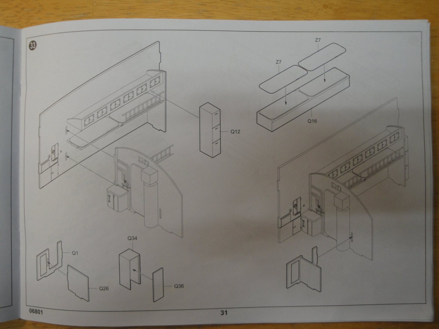
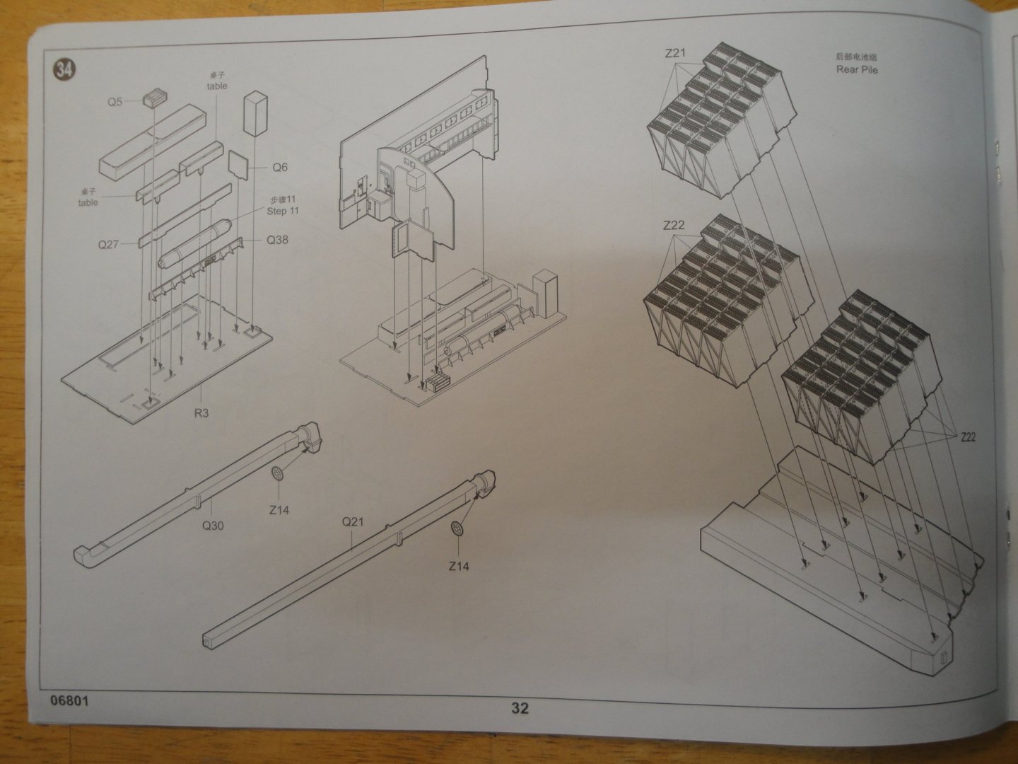
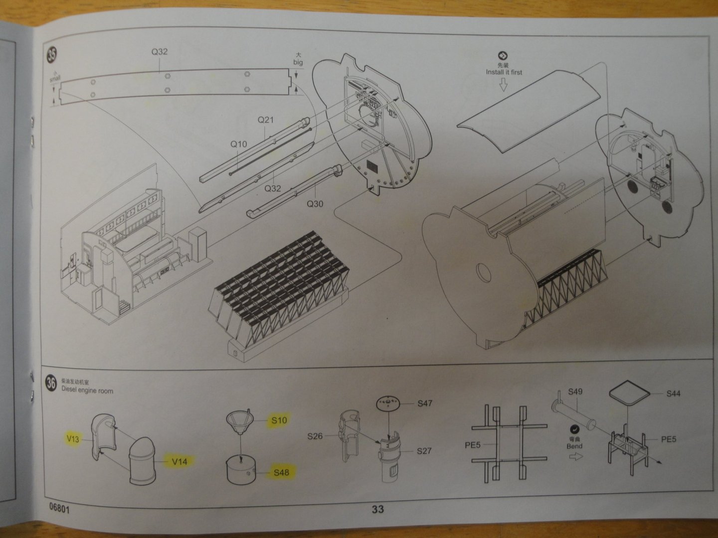
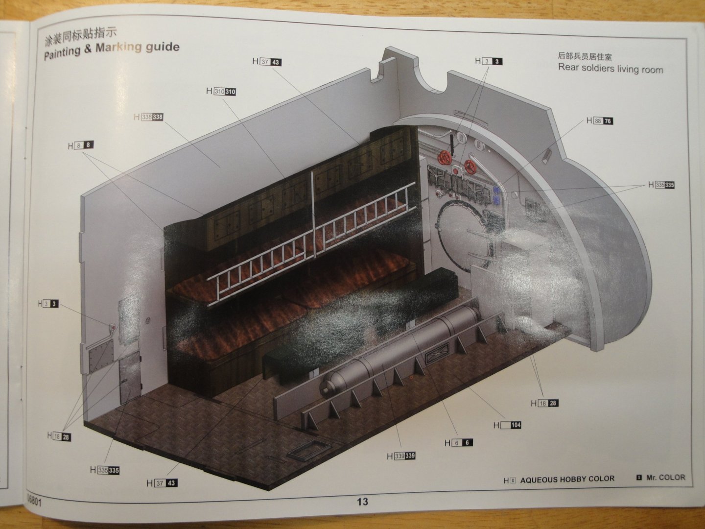
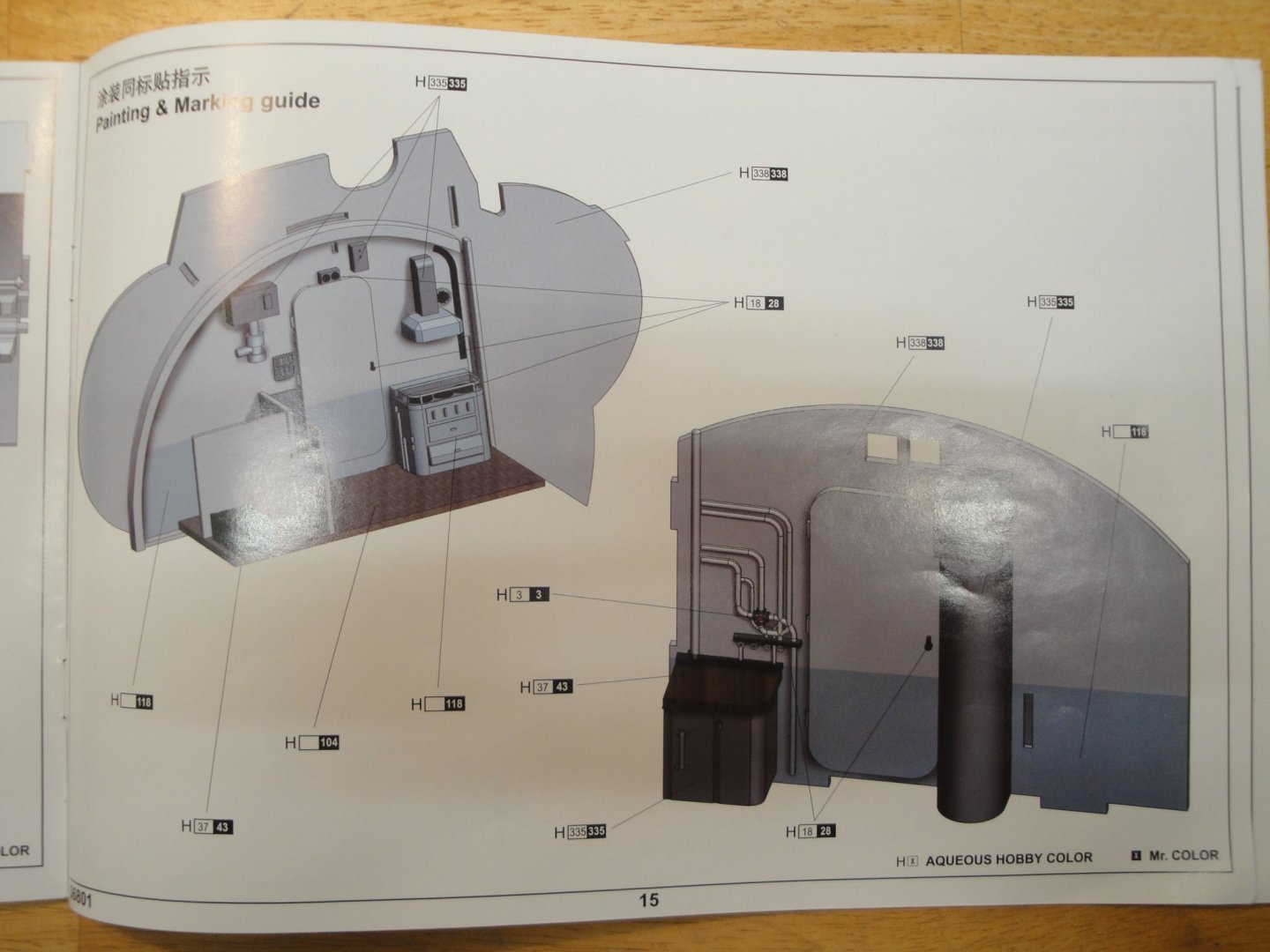
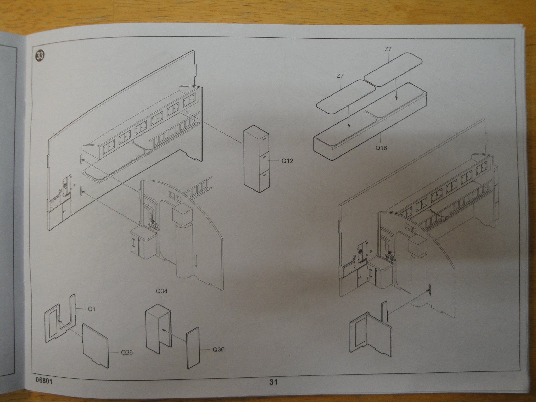
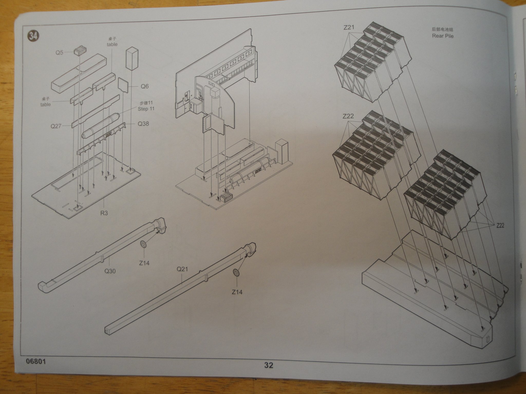
I am not ready to come back quite yet.... Just thinking ahead of what is to be built: the Unter-Offizier raum and Kuche ! This compartment is located forward of the Diesel engine room and after the Control Room. Although at first sight it resembles the previous Offizier Raum, it differs from it by a lot of details. The Fuel tanks are not so large and arranged differently. They also share the space with water tanks, for the crew. This view shows what I am talking about. Batteries are in the same location, more or less, but the side fuel tanks are smaller on the aft compartment. The compartment includes sleeping berth, kitchen, restroom and some storage spaces: The Sleeping area is surrounded by one Fresh Water tank and by a Grey Water tank, used for cleaning. These two large tanks seat on top of the Fuel tank. Finally, we have a Waste Water tank located behind the batteries, on the lower level: As you can easily guess, Trumpeter has not provided any of these important details. Therefore, we will have to fabricate some walls and re-organize somewhat the original kit. Below are the Trumpeter instructions as an appetizer: Yves