HOLIDAY DONATION DRIVE - SUPPORT MSW - DO YOUR PART TO KEEP THIS GREAT FORUM GOING! (83 donations so far out of 49,000 members - C'mon guys!)
×


yvesvidal
-
Posts
3,607 -
Joined
-
Last visited
Content Type
Profiles
Forums
Gallery
Events
Everything posted by yvesvidal
-
 Wonderful. These are some of my favorite boats and I hope to build one at the same scale, one day. I will be watching with a lot of interest. Yves
 -
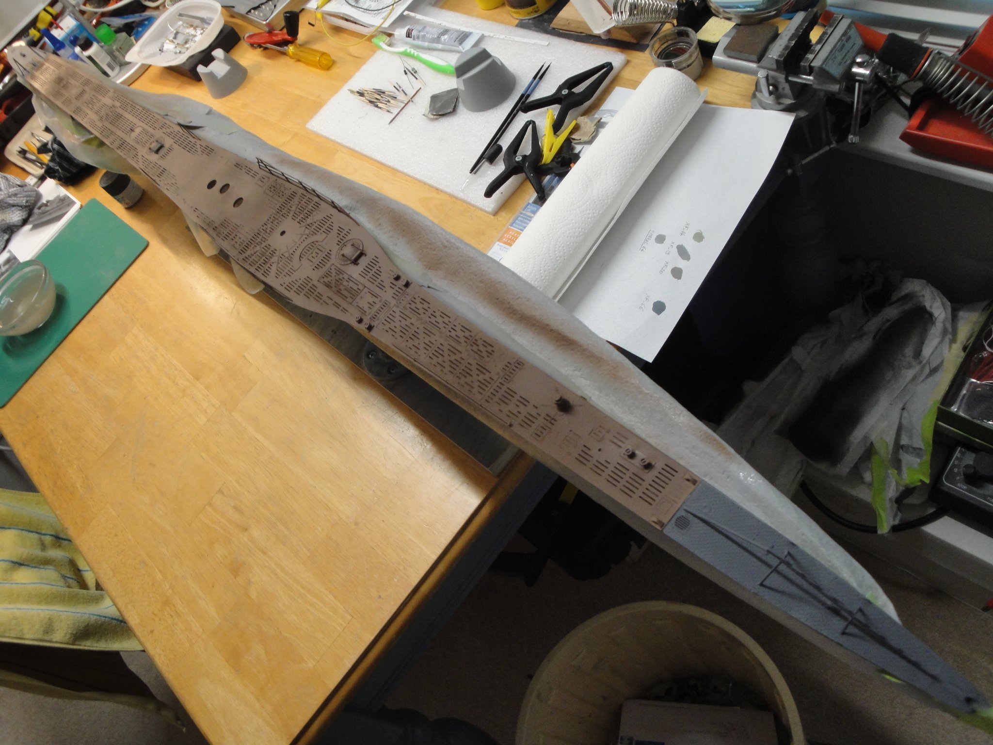
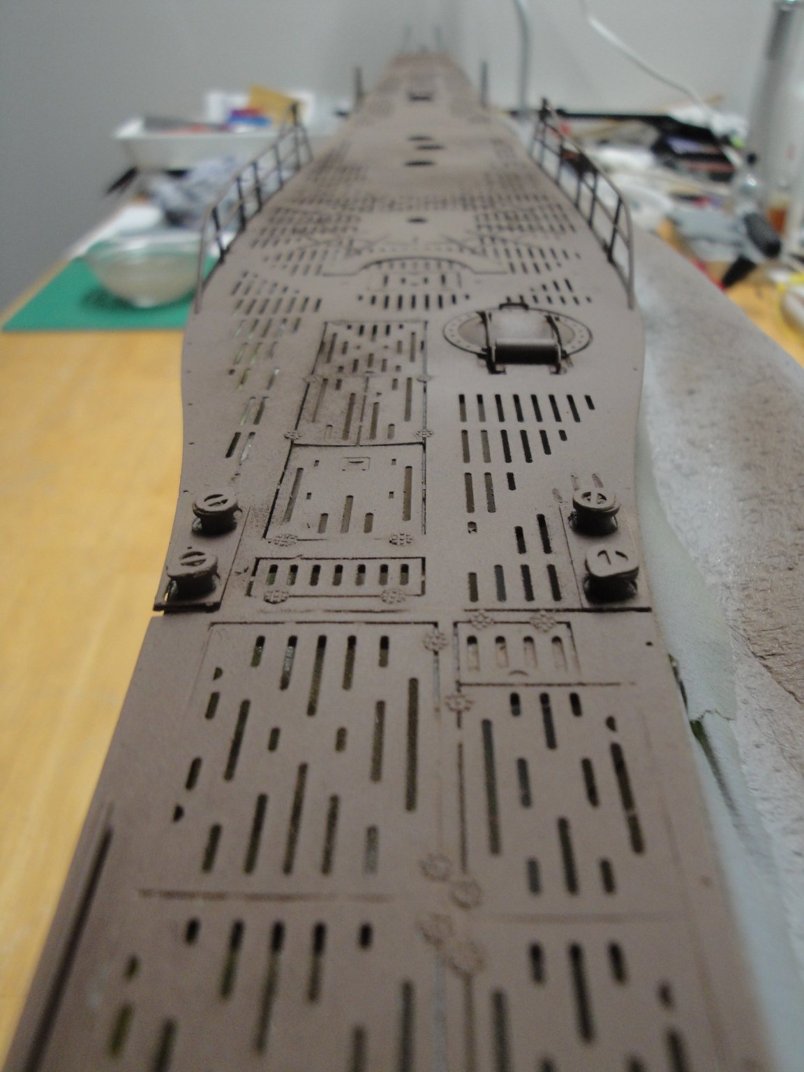
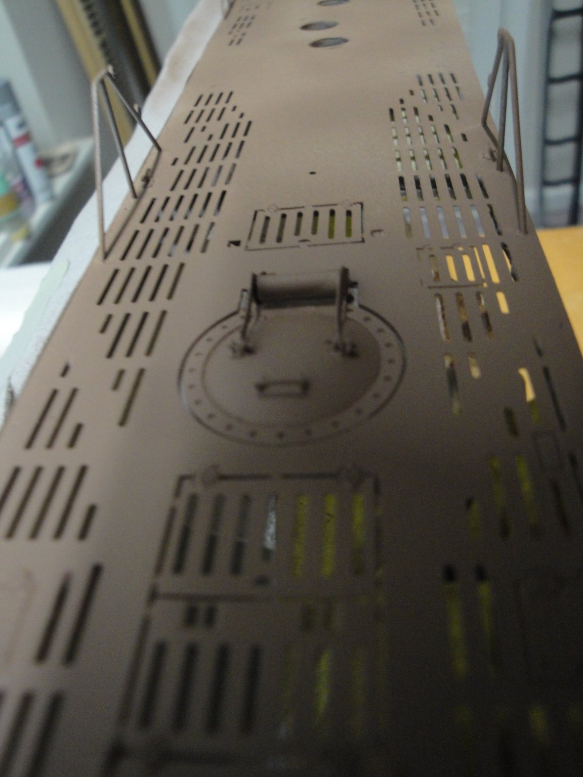
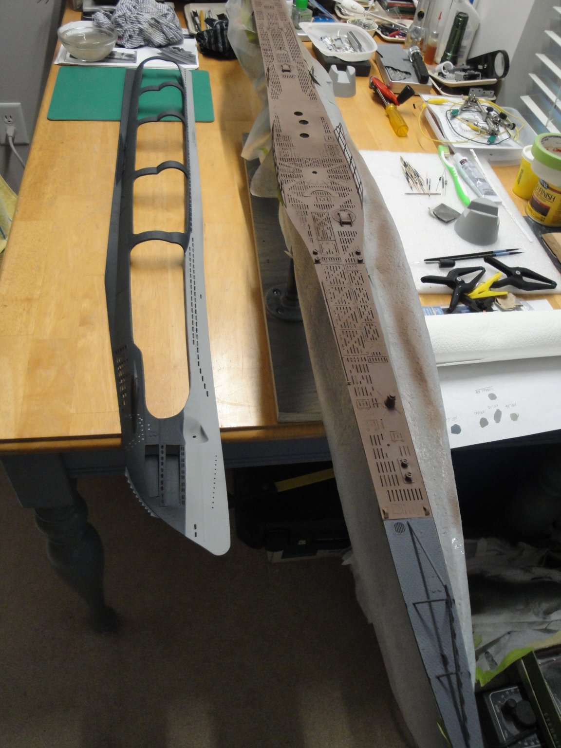
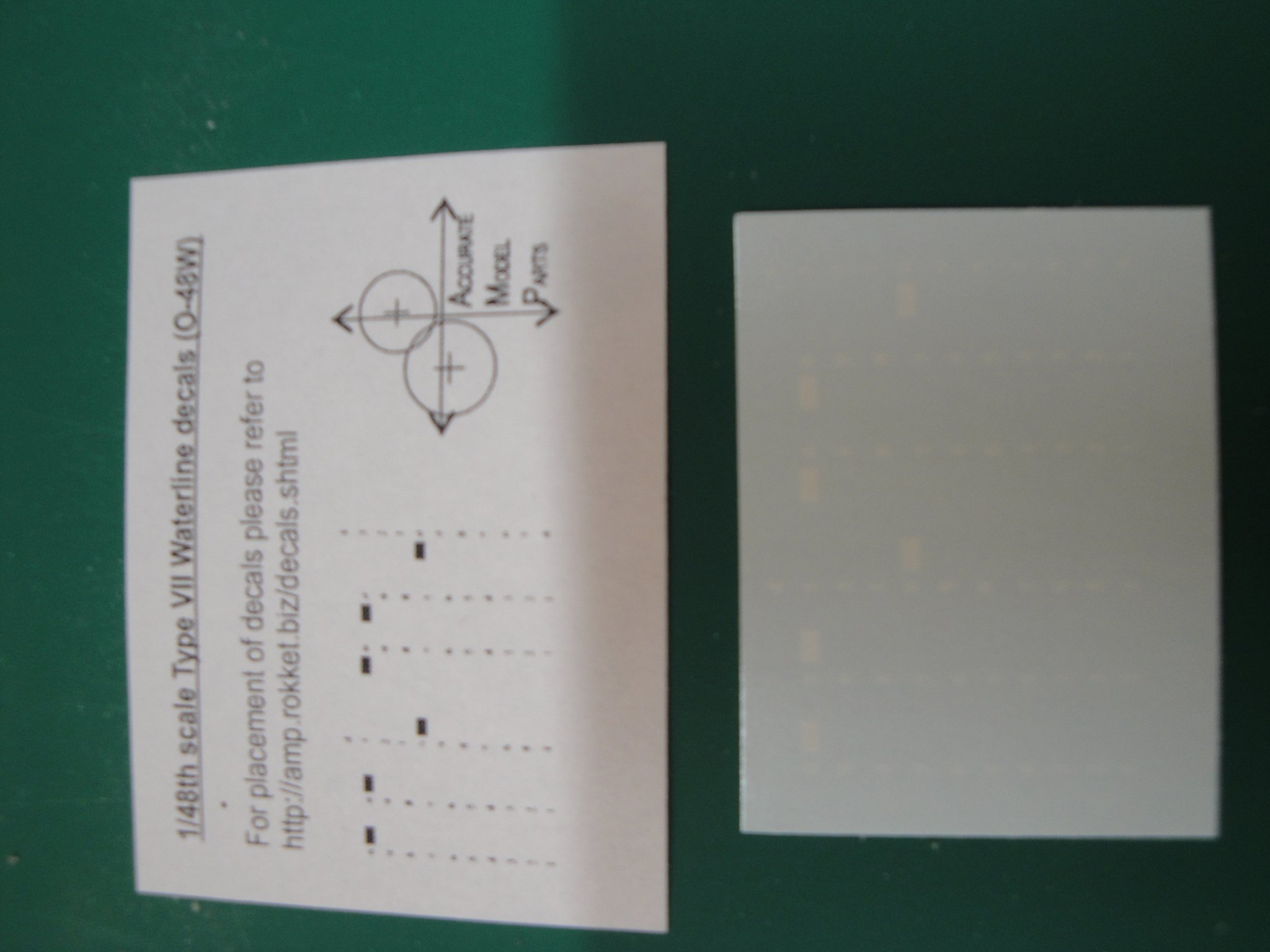
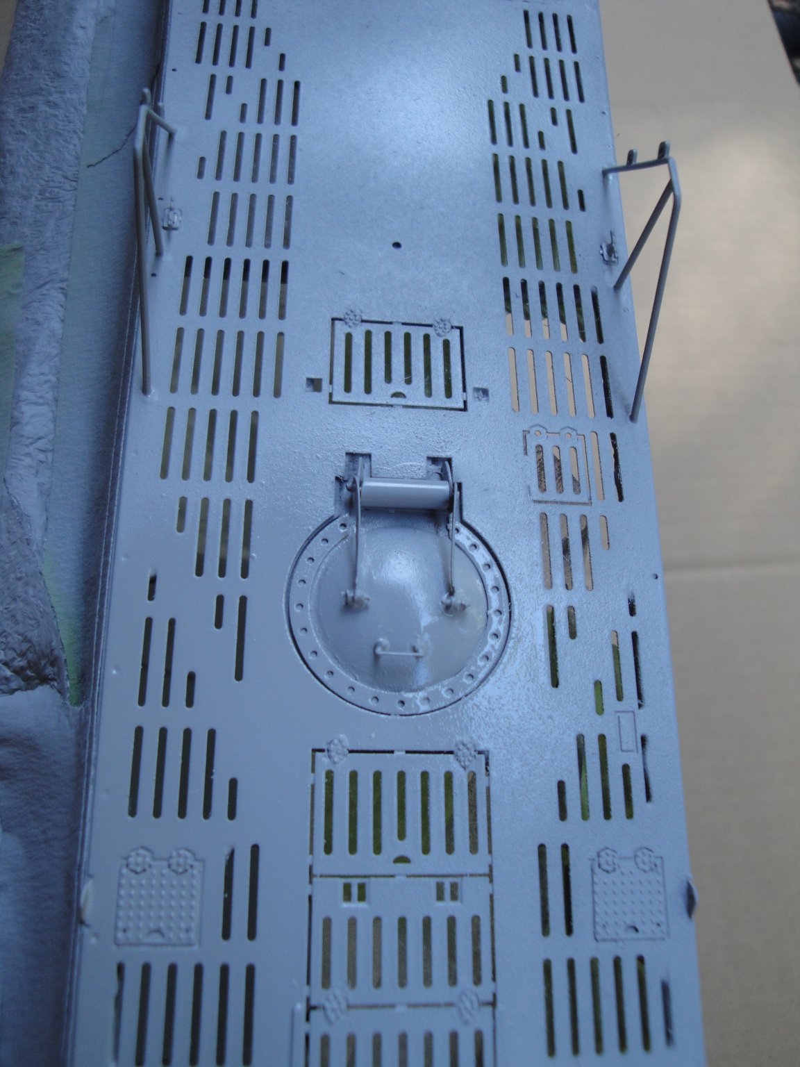
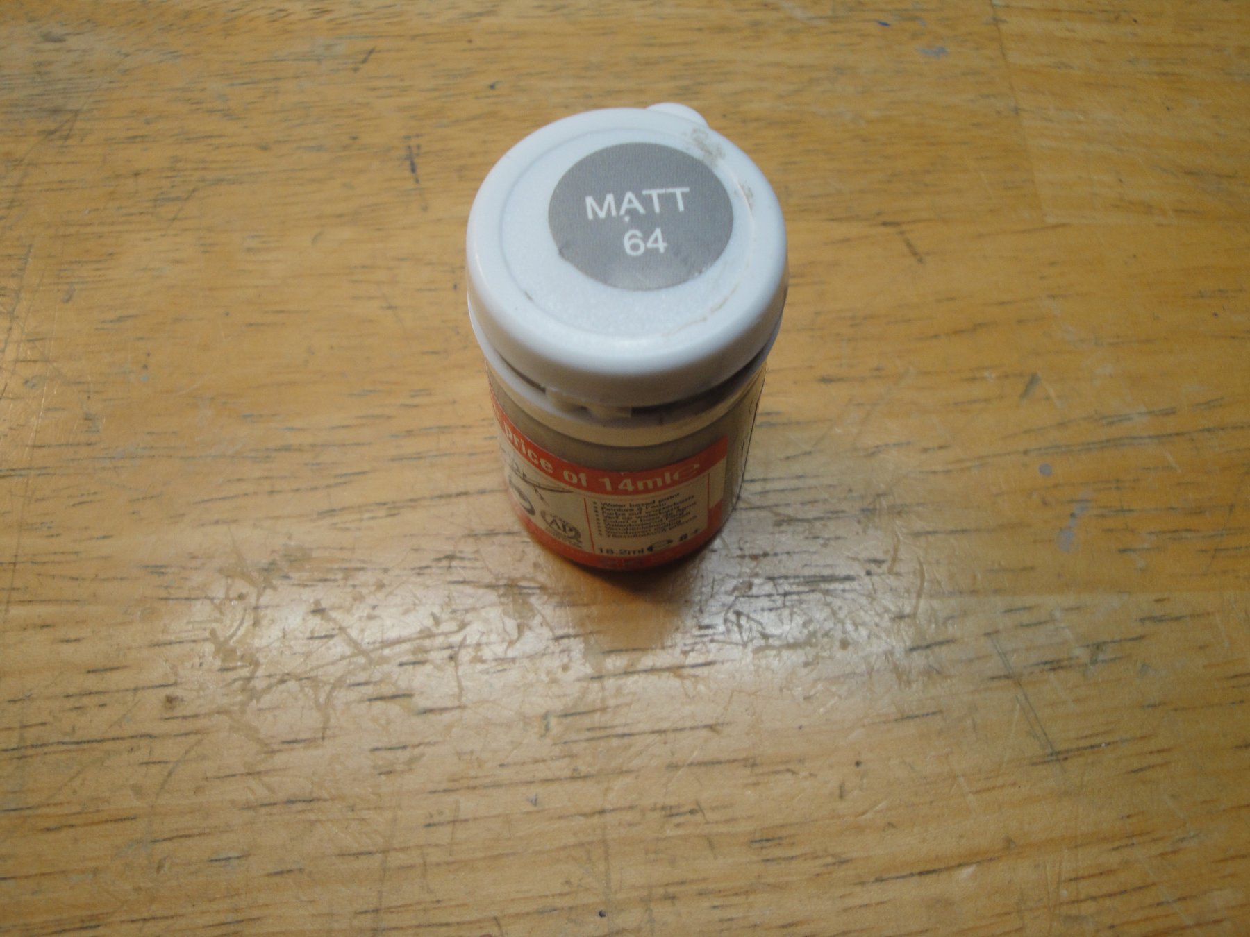
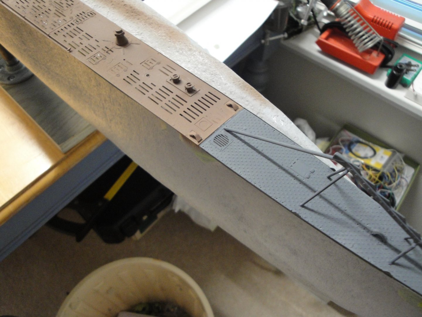
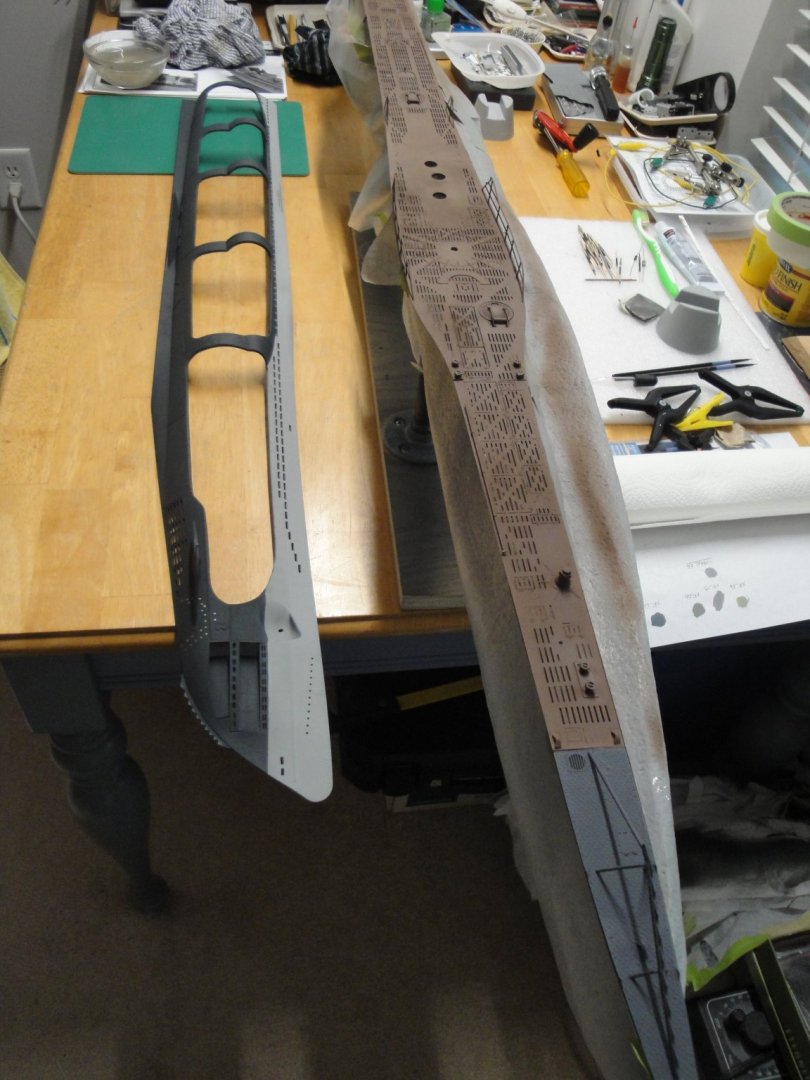
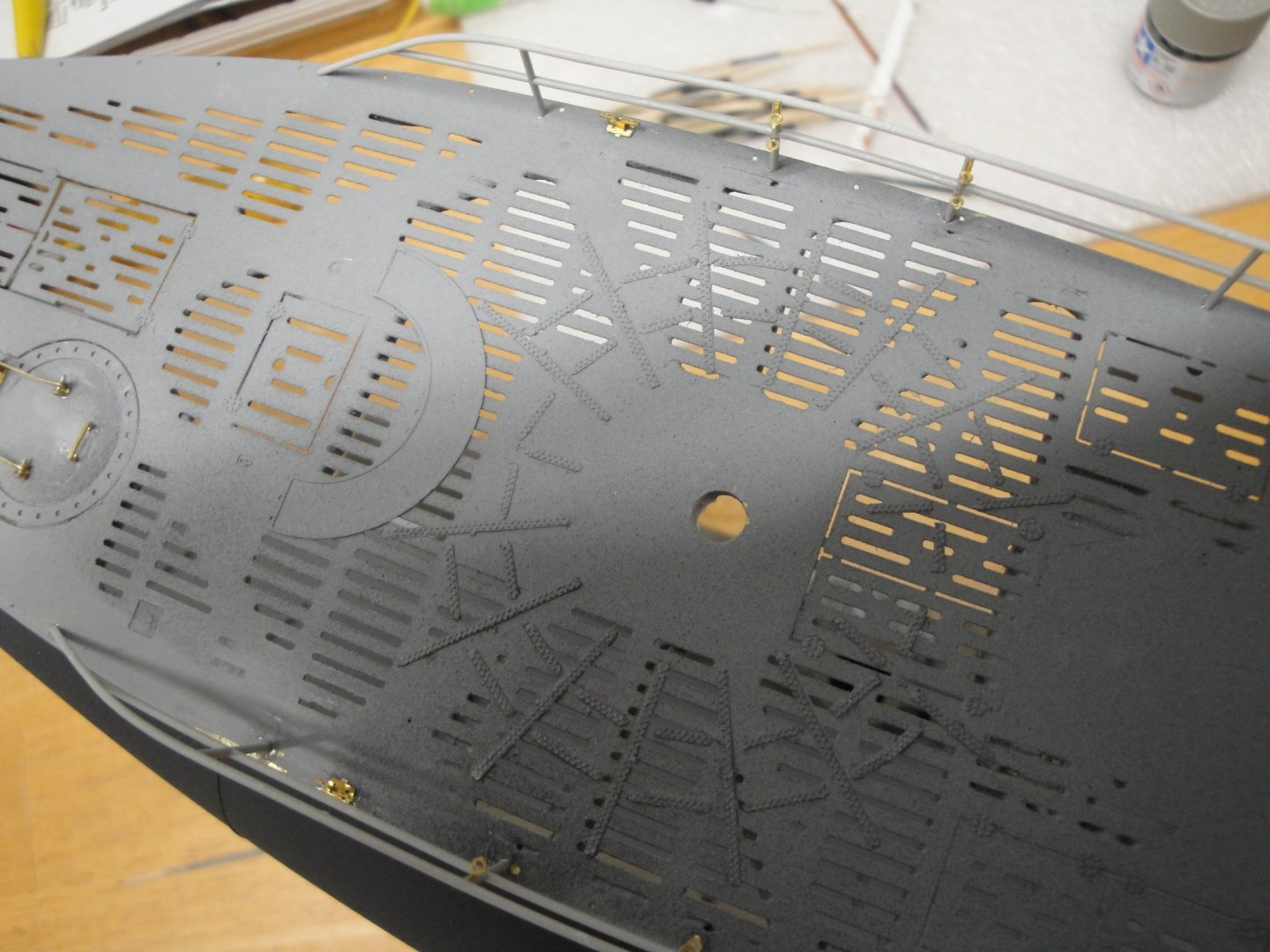
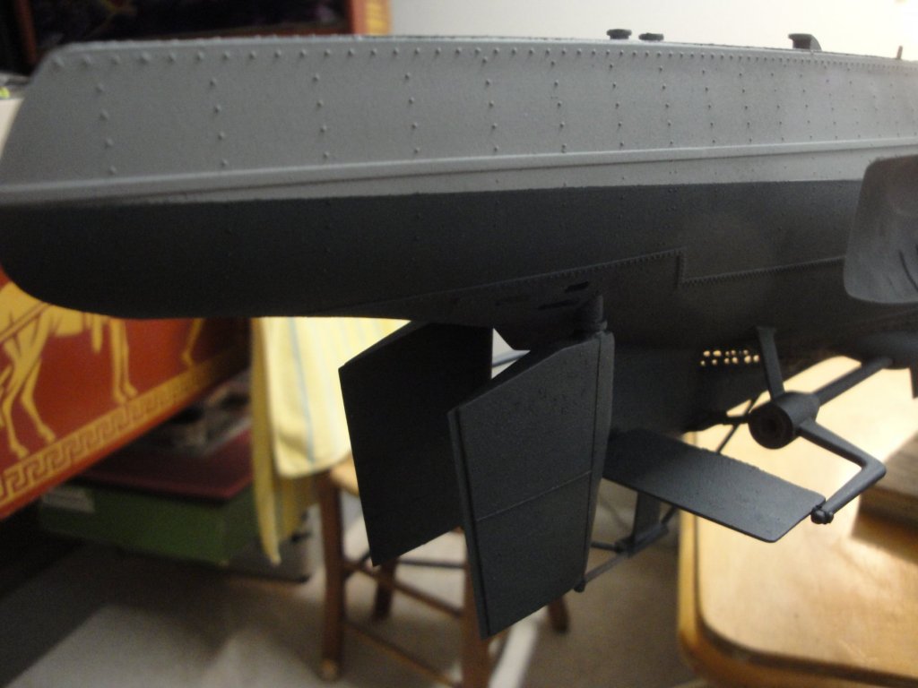
Deck has been painted: The bow and stern platforms are painted with Tamiya Dark Grey XF-24. The rest of the deck is Tamiya XF-64 to simulate the German tar that was spread on metallic deck to prevent sailors from slipping at sea. That tar, originally darker was fading very rapidly with the sun light and the salt. Once the hull has been clear coated, I will try to add some shadings and washes in different locations. That PE deck from RCsubs really stands out. I have been watching some pictures on the web, of the same model where the Trumpeter plastic deck is painted.... and there is absolutely no comparison. It was a lot of work but worth every dollar and drop of sweat. The entire hull is now ready for the waterline decals (just received them from England) and a final mat clear coat to seal everything before the big challenge of weathering. The decals from AMP: Once set on the dark hull, they will be more visible. Yves


- 760 replies
-
- 17
-

-
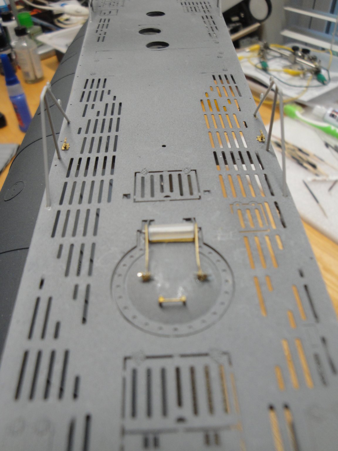
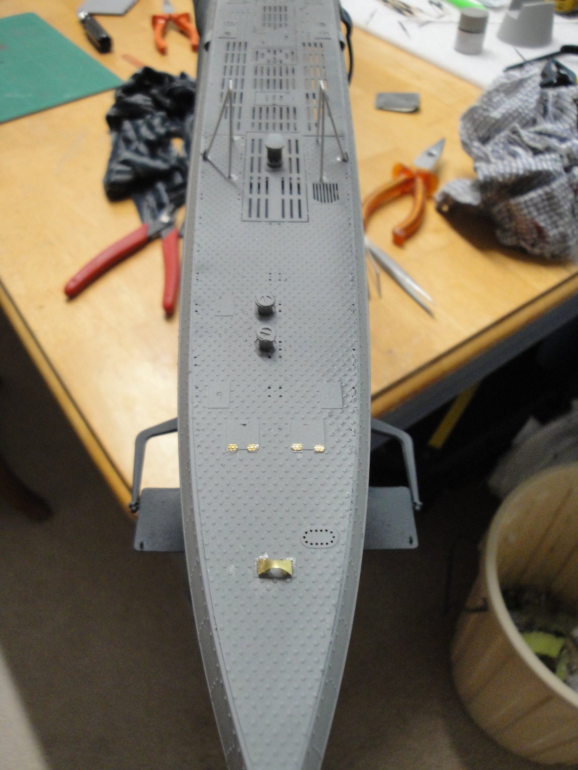
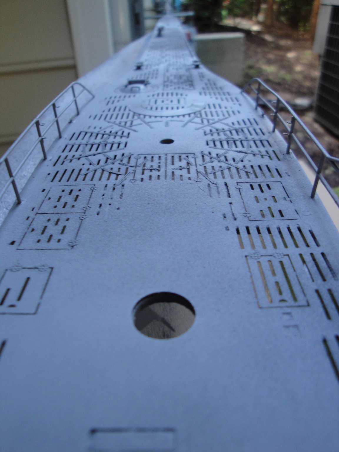
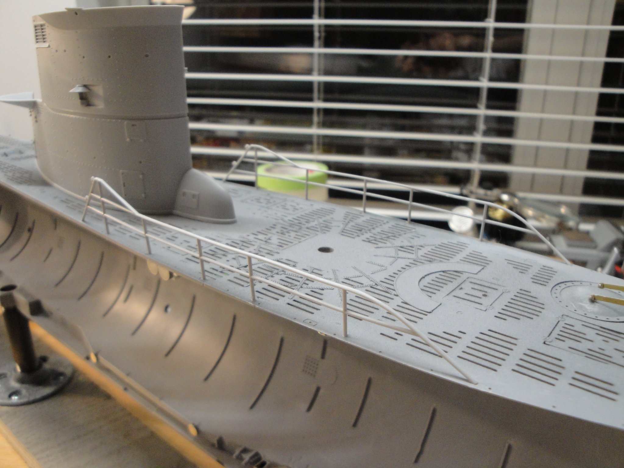
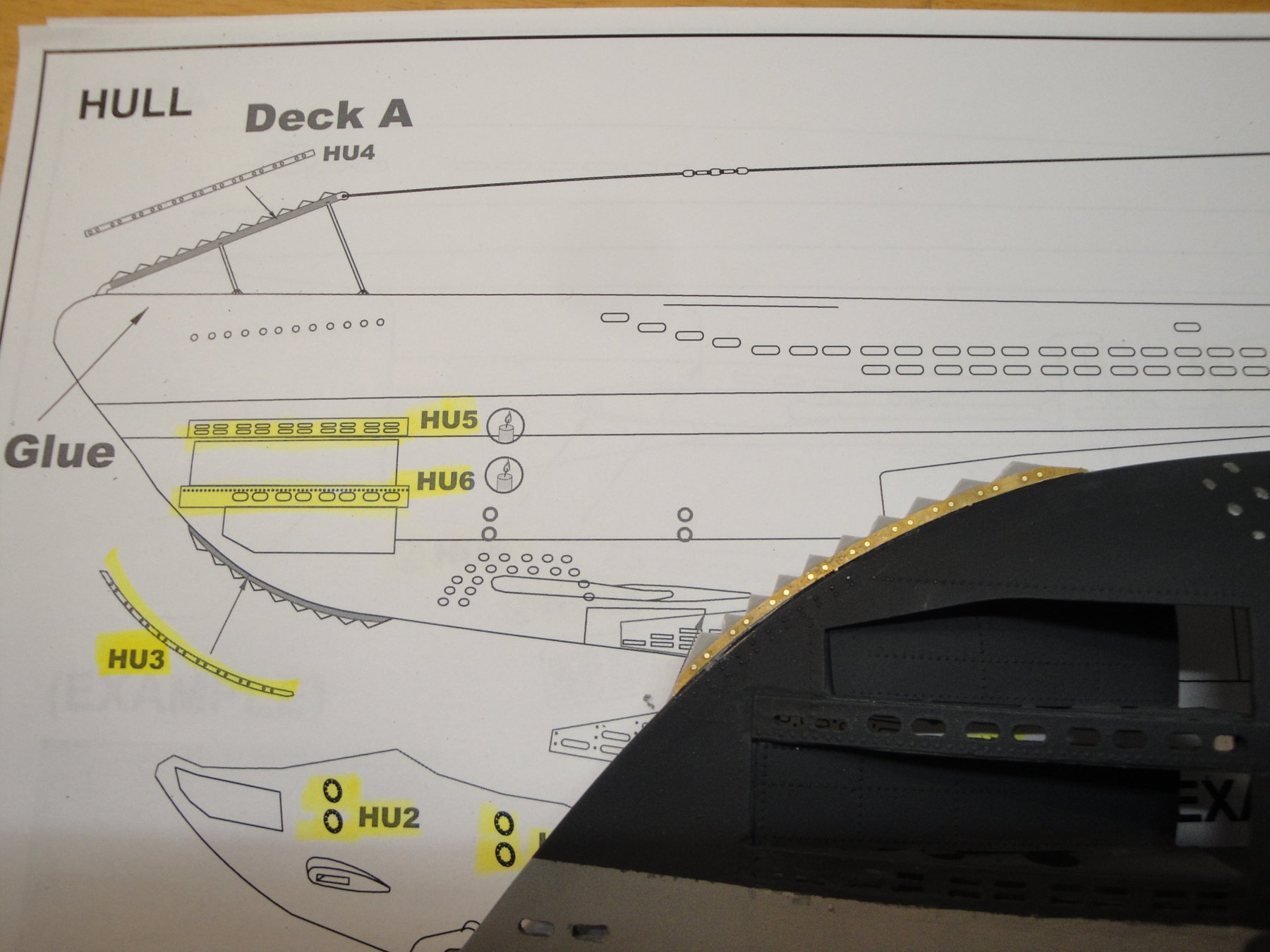
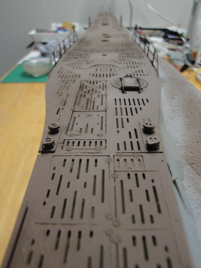
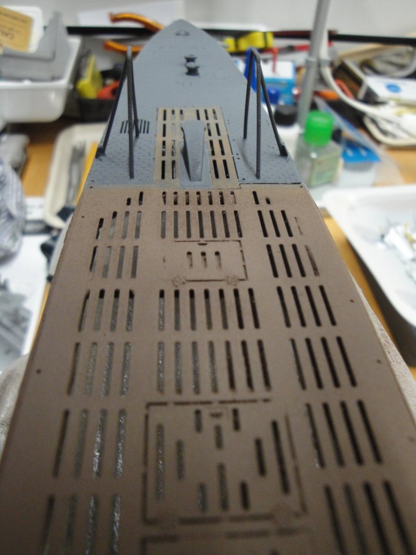
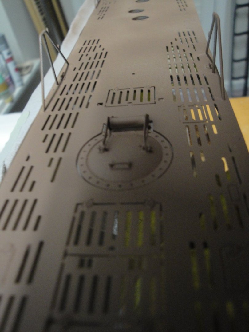
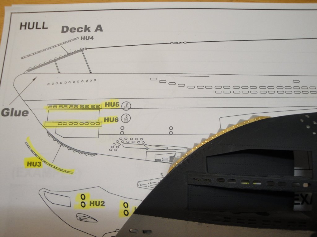
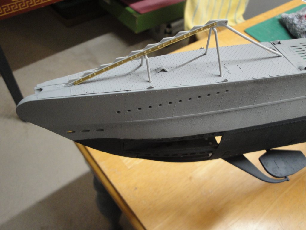
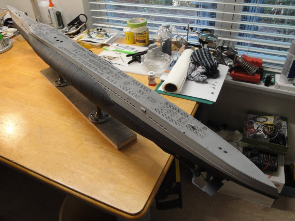
I have been trying to finish the deck, before painting it. Lots of small details and PE parts went on it: Then it is masking time: And a coat of automotive primer to harmonize the whole: Once, the Primer is dry, I will be in a position to start painting the deck. Some pictures: Yves


- 760 replies
-
- 17
-
-
Comment ai-je pu manquer ce thread? FrenchGuy, vivant a Lexington, MA et passione de modeles de bateaux. Ce ne pouvait etre que Stephane Greppi. Comment vas tu? Je suis impressionne par tes realisations et la Barque a vapeur Alexandra (c'est aussi le nom de ma fille) est absolument superbe. Je n'ai pas fait grand chose mais j'ai un ou deux threads sur ce forum: Celui-ci etant le plus actif pour lemoment. Au plaisir de te lire. Yves
-
Pittman does some very nice and powerful motors, too. They are built in the states, but are more expensive. Yves
- 52 replies
-
- 2
-
-
- dumas
- Chris-Craft
- (and 1 more)
-
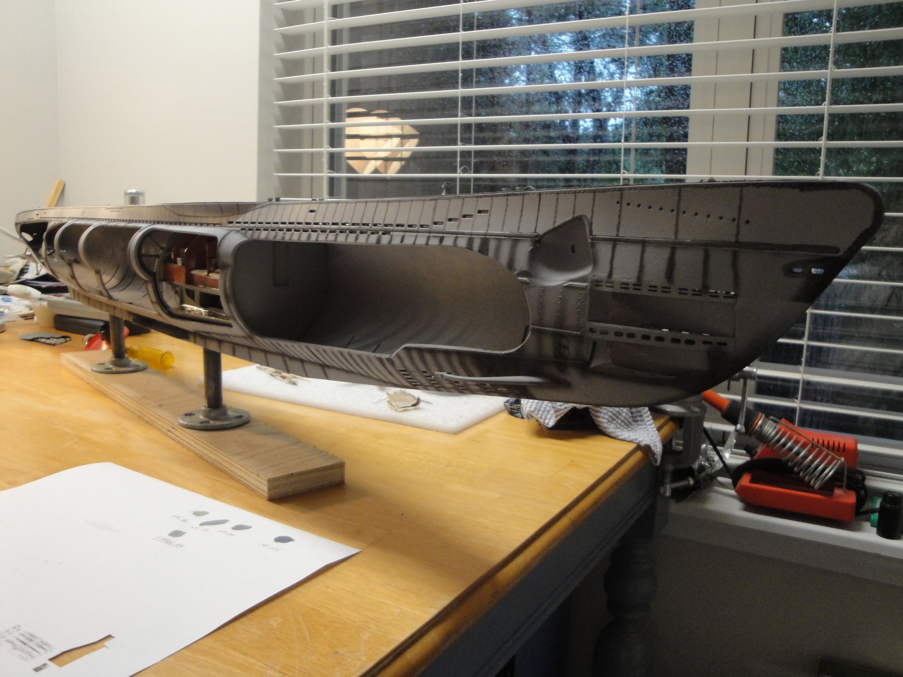
Working from Bow to Stern, little by little.... Things are getting very delicate. This large hull must be manipulated with care. Yves

- 760 replies
-
- 21
-
-
Nils, this is superb. I love the models that shows the inside intricacies and offer some educational contents. You need to replace the engine mounting screws with some mini-bolts. They look way out of scale. Yves
-
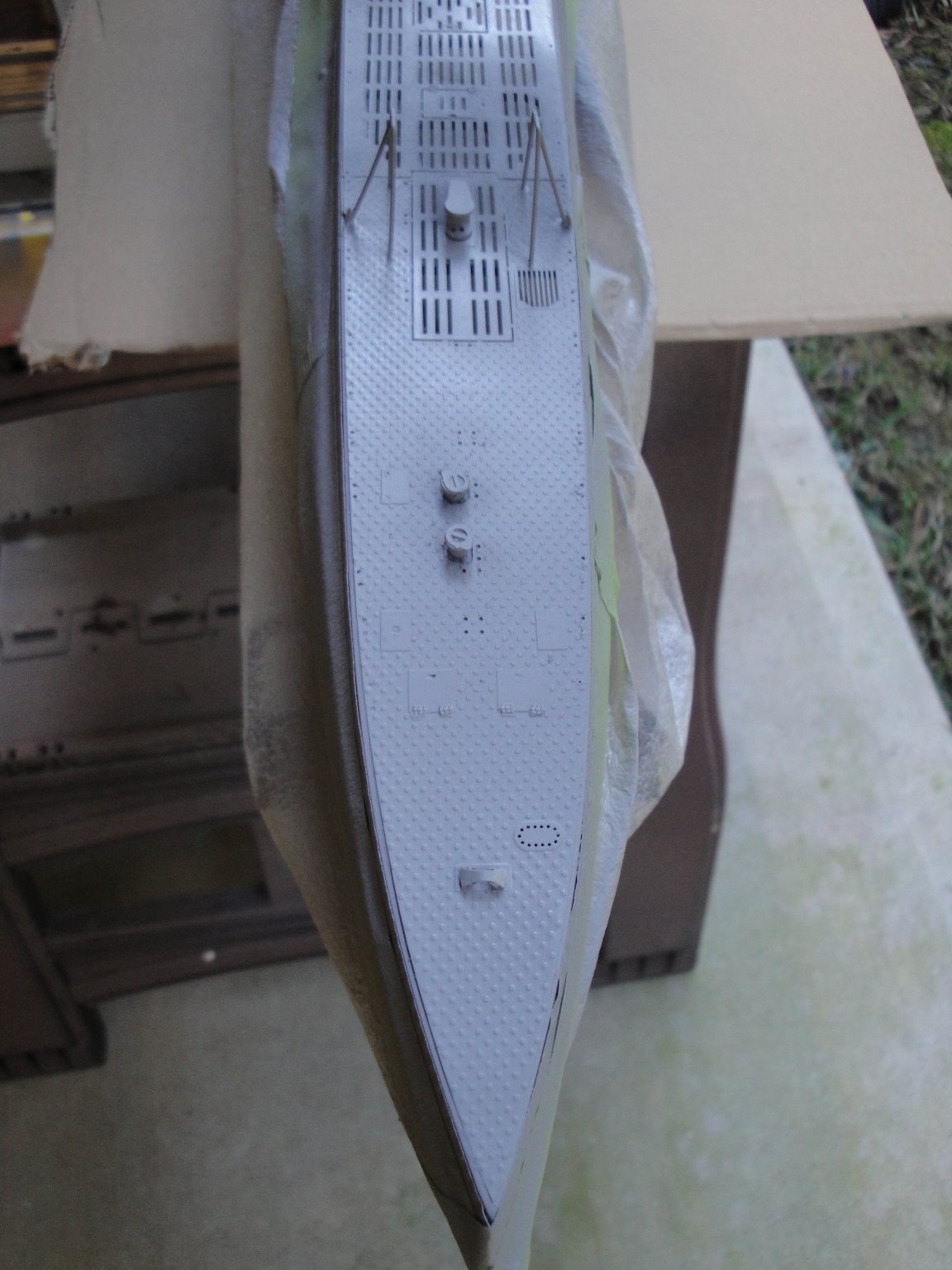
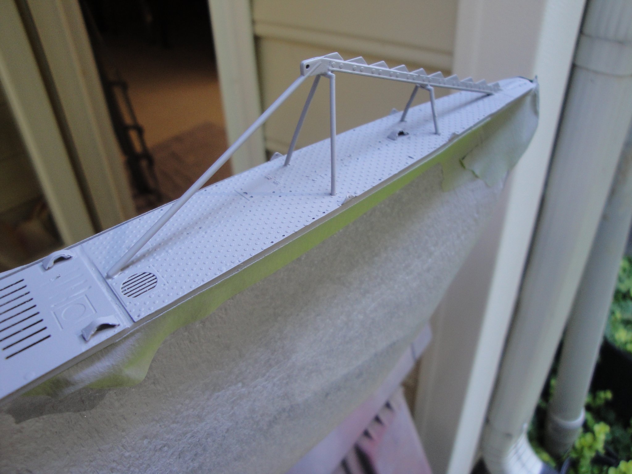
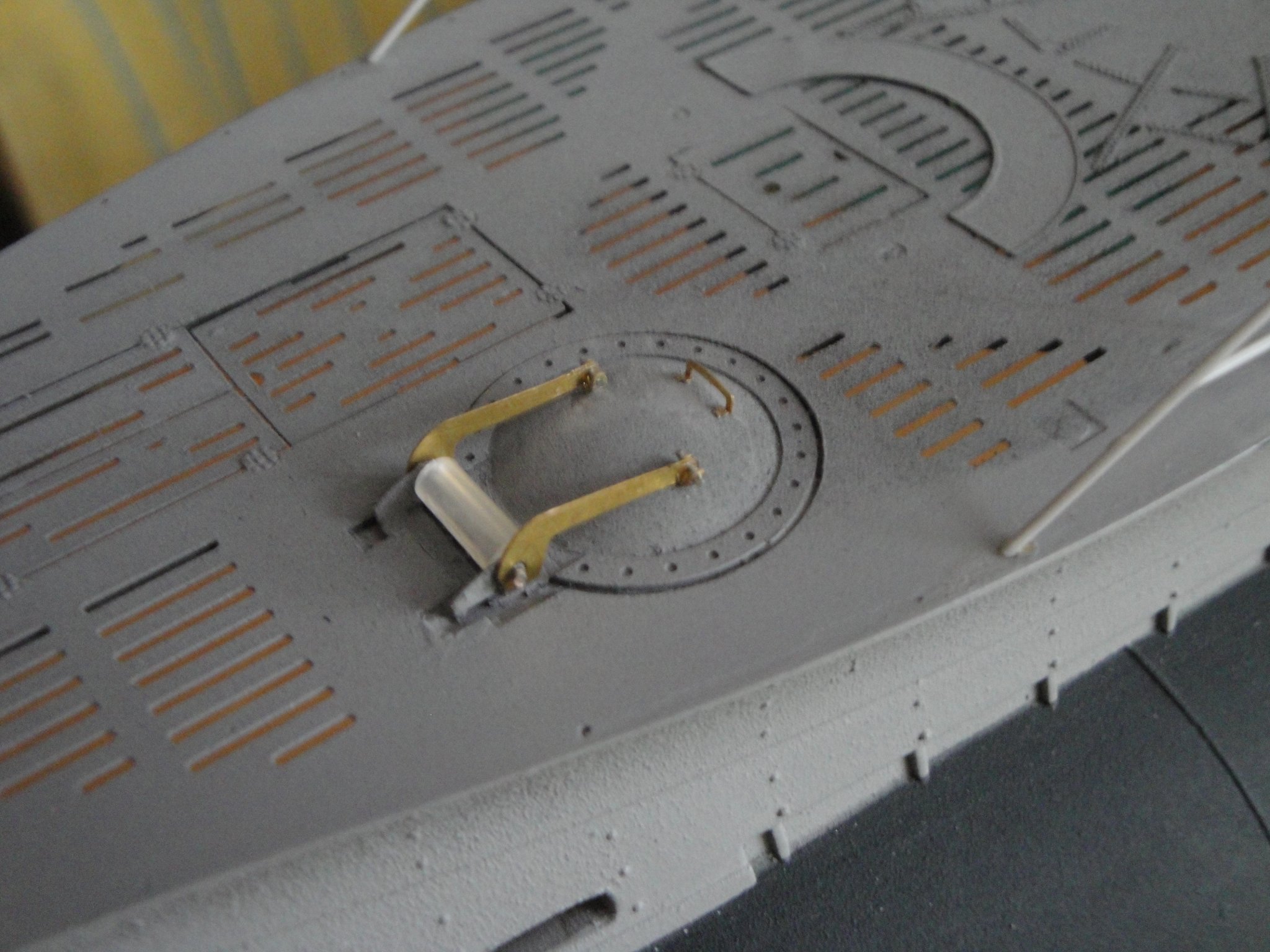
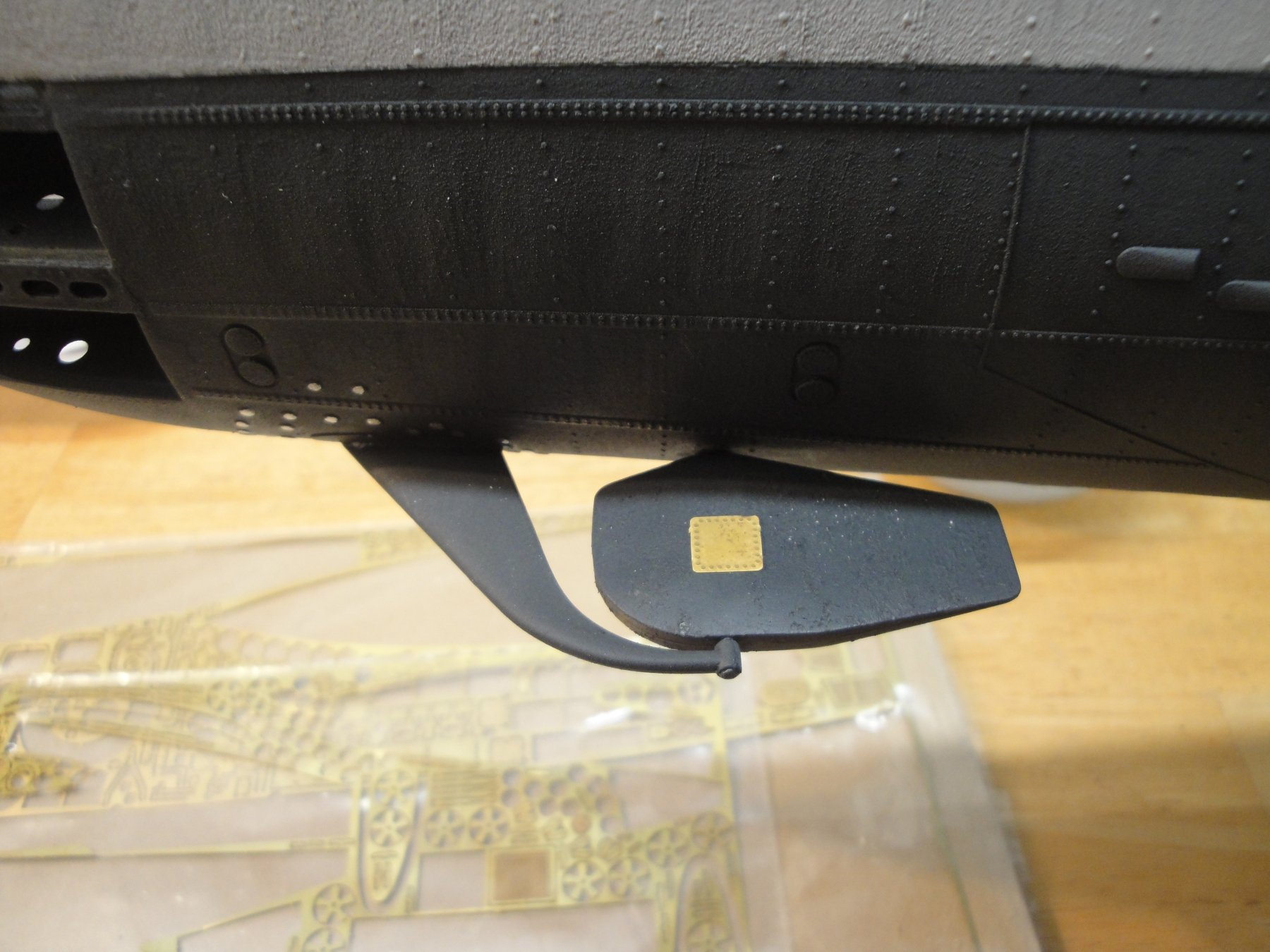
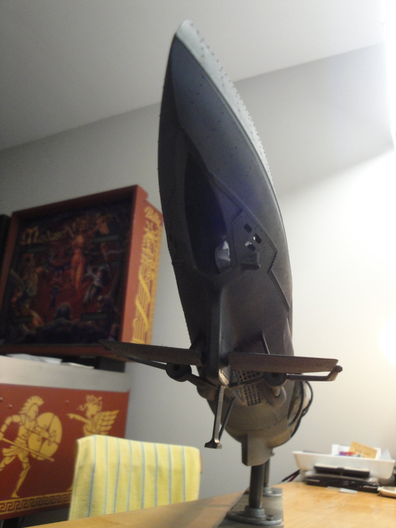
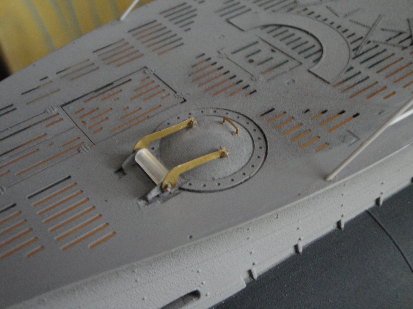
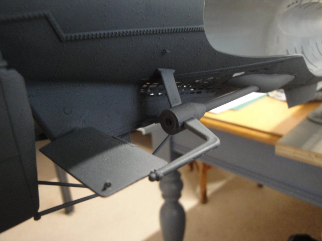
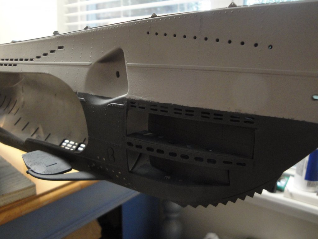
Still a few small updates, working on details that make a difference: 1) The anodes on the diving planes, provided by the RCSubs PE set: 2) The menacing teeth, used to cut nets and underwater cables (again pimped up by RCSubs PE set): 3) The rings to attach the crew/sailors when working on untangling the propellers or doing the maintenance of the rear diving planes (Intermountain parts in 1/48th): 4) And finally the net/cables cutter on the top of the bow (again pimped up with RCSubs PE set): Little details, very fragile, but which are slowly turning this kit into a realistic Type VIIc model. Yves

- 760 replies
-
- 22
-
-
There won't be much in terms of updates. I am waiting for parts and paints. Can you believe that Trumpeter omitted to provide the Waterline markings on their (otherwise nice) decals sheet? I realized that yesterday and was really surprised by this mishap. Fortunately, I found a British company Accurate Model Parts that do sell the Waterline markings as well as a few other things for the Trumpeter kit. I also have on order some Tamiya paints and clear coats and do not know how long it will take to come here. Tamiya products are starting to be very rare if you want a color other than the Fluo and Neon Orange and Green. Yves
-
Glad to see you back on this lovely model. Most likely, one to become the ultimate reference! Yves
-
What a superb model. Yves
-
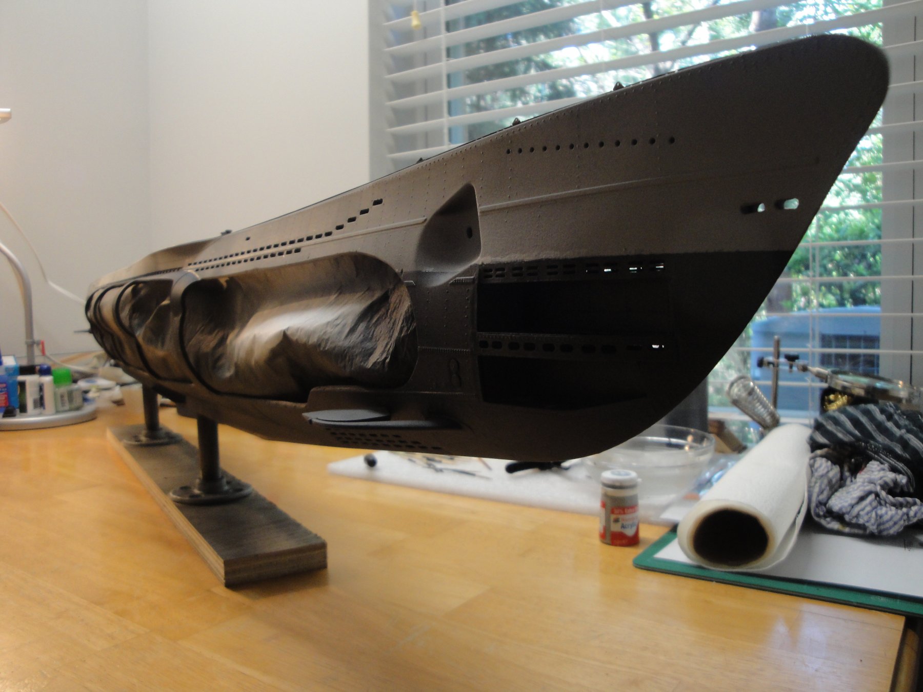
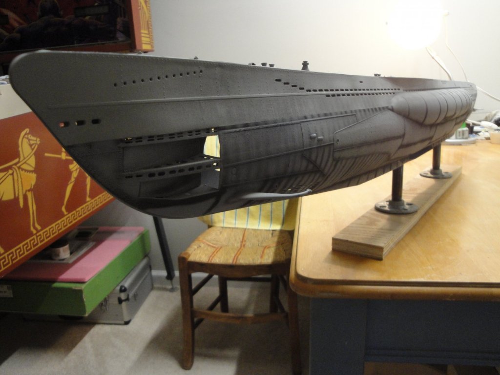
The rudders have been glued: I really like the color and texture of that big hull: Yves
- 760 replies
-
- 20
-
-
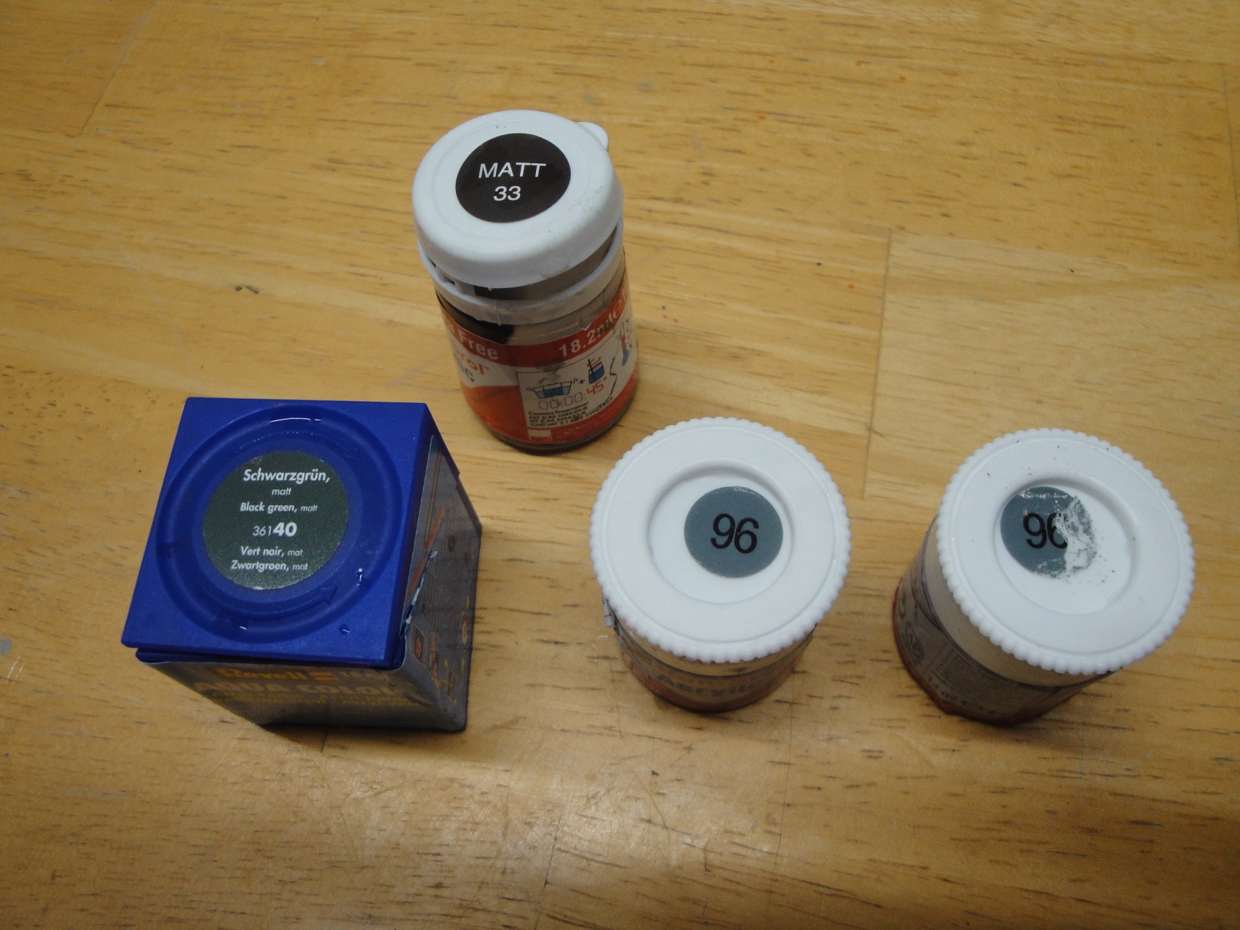
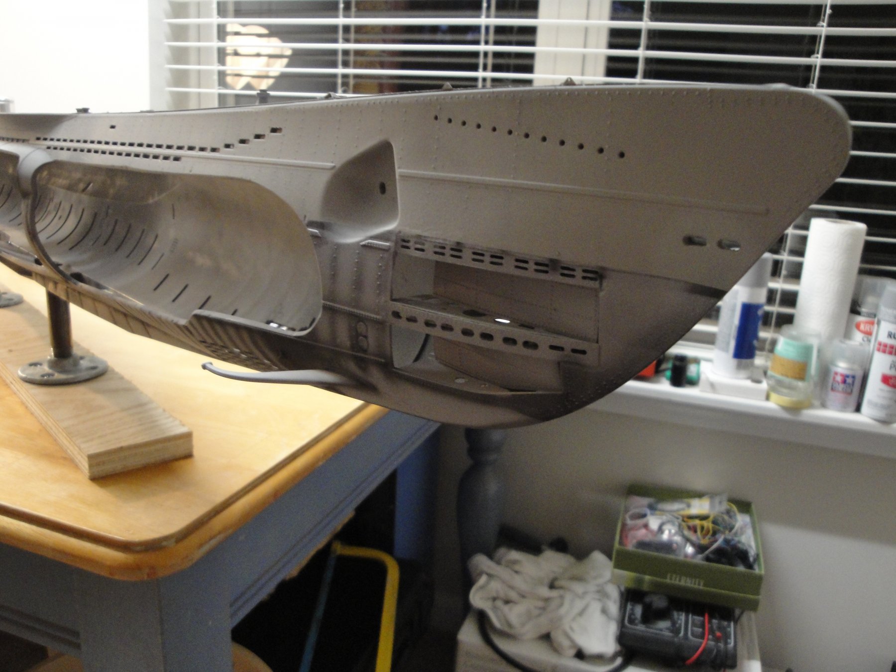
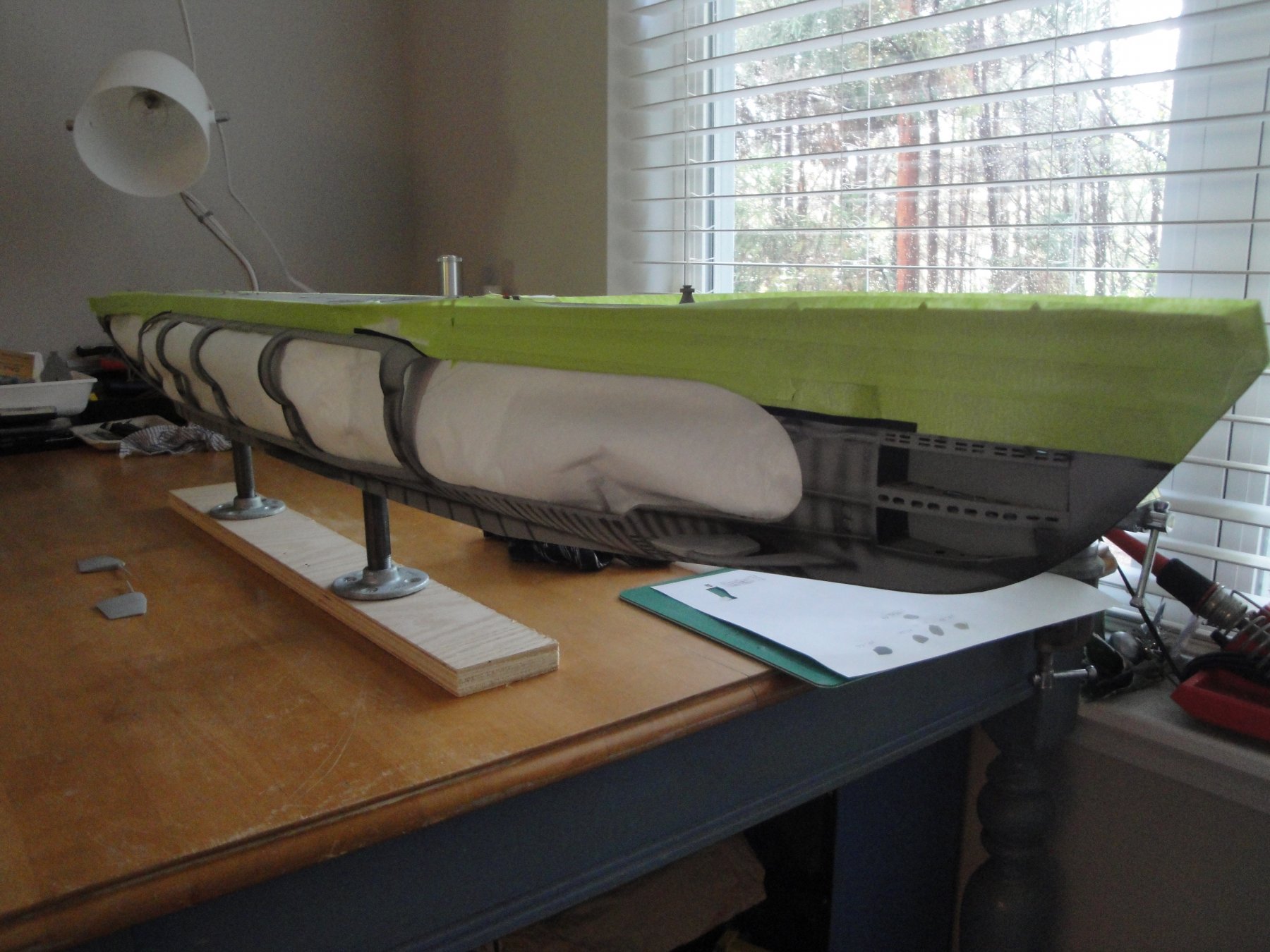
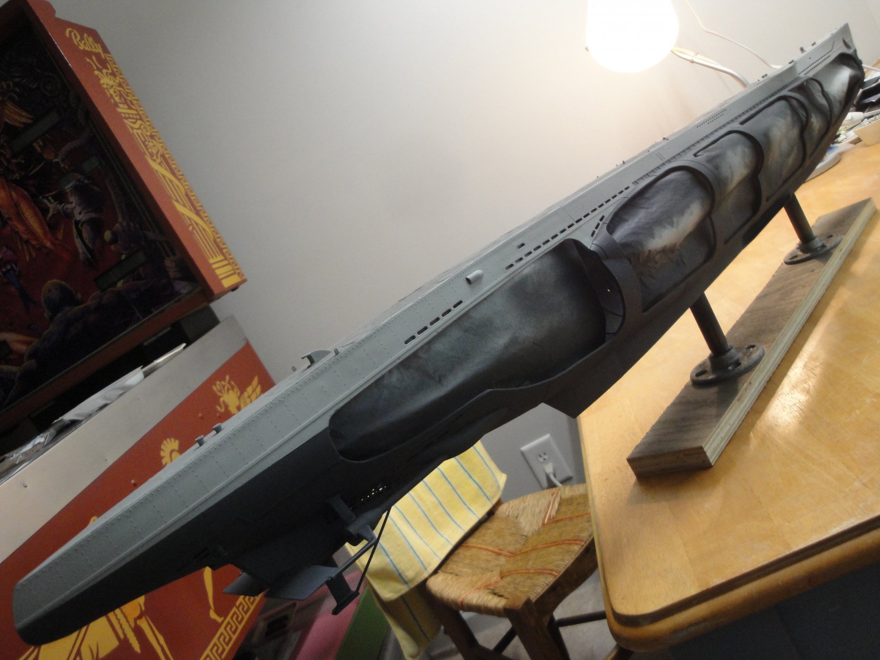
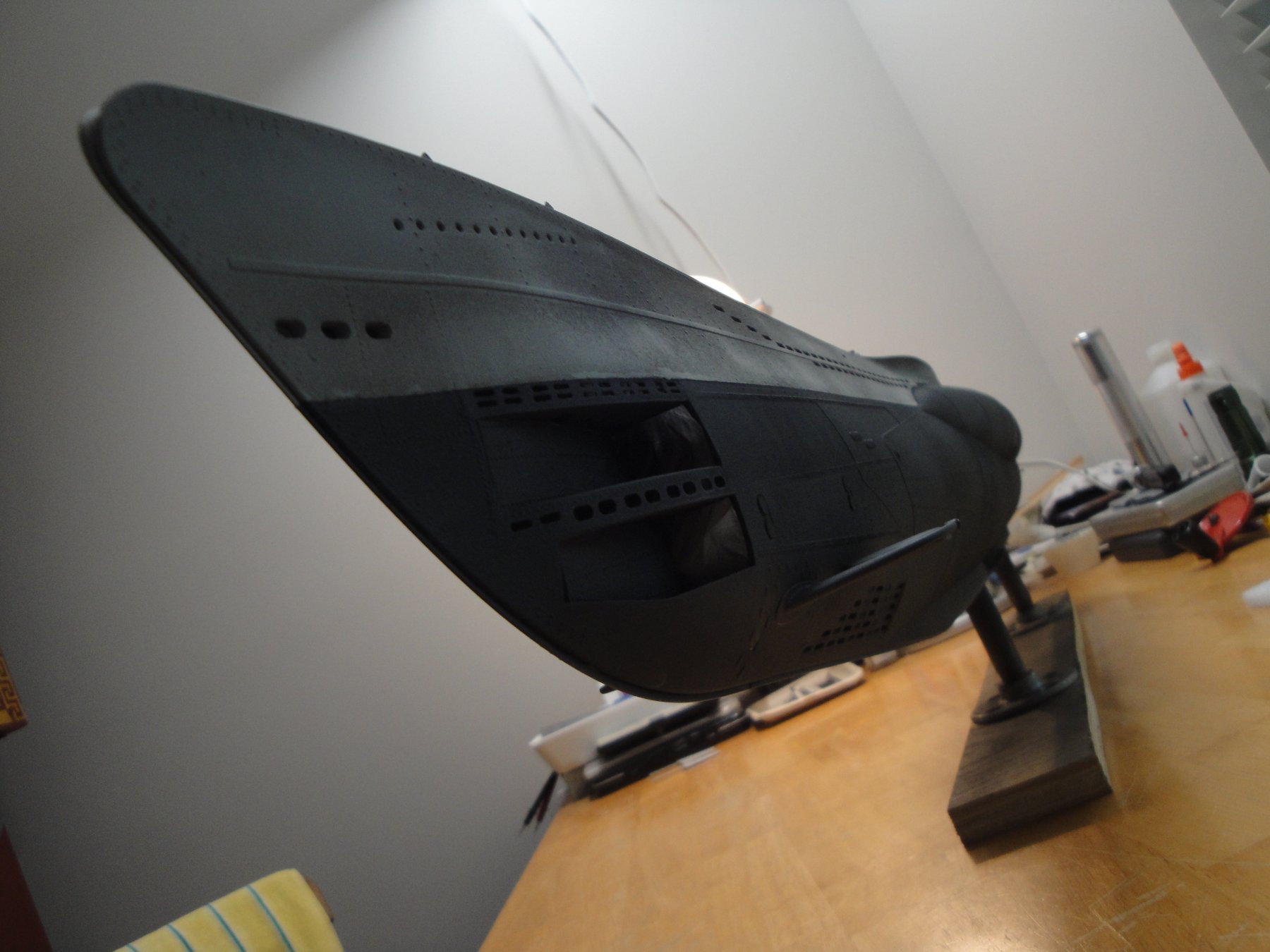
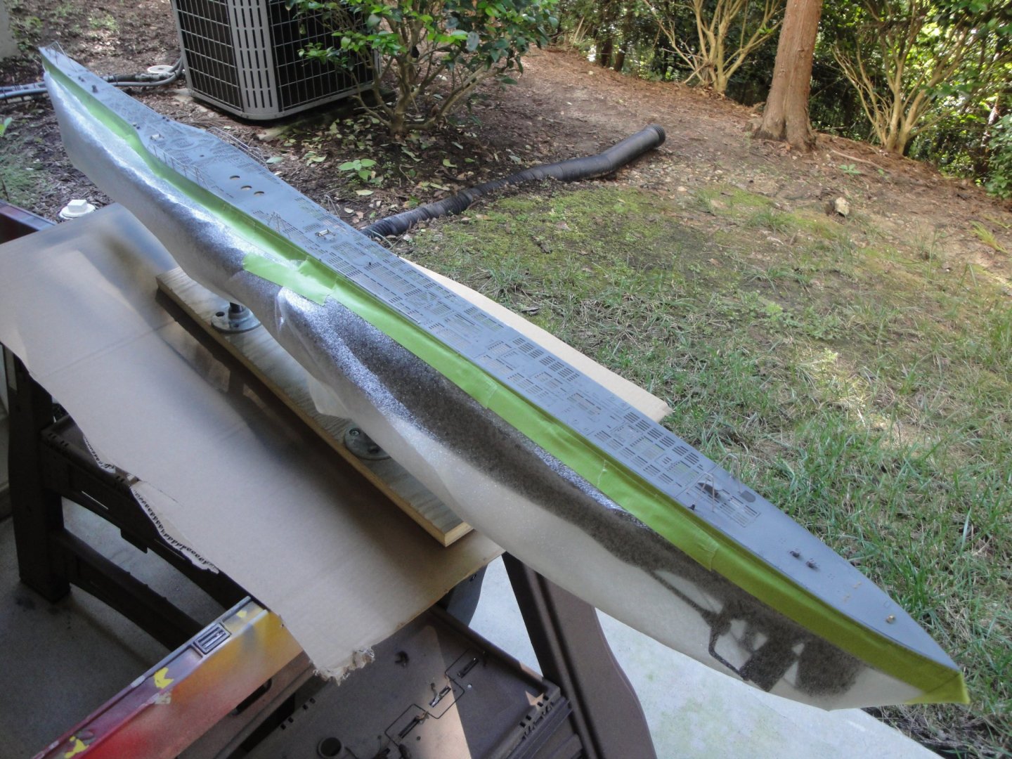
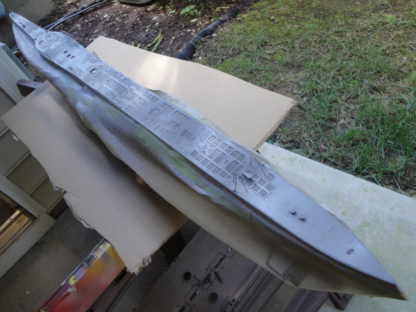
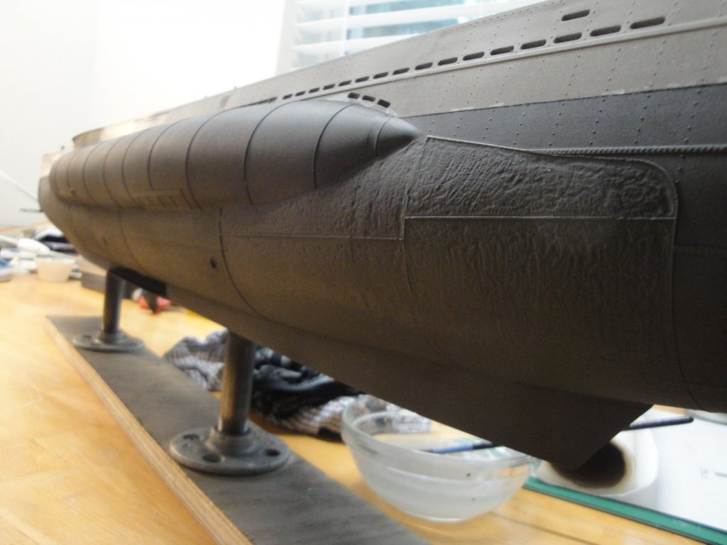
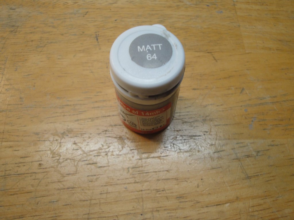
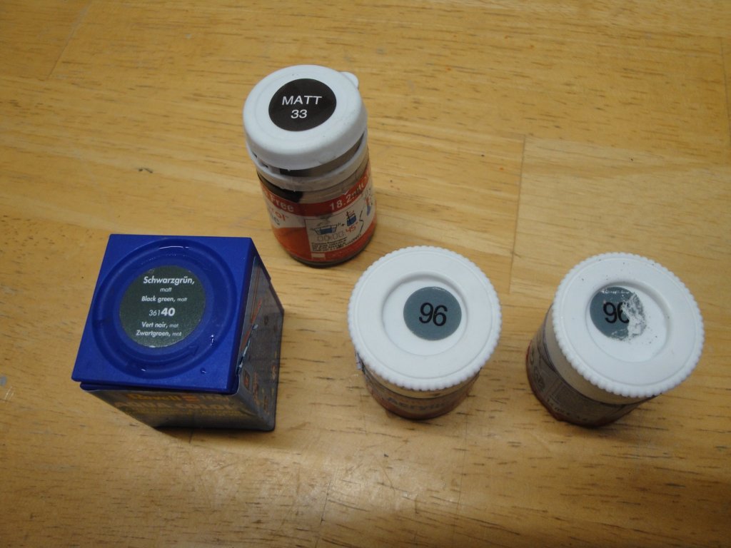
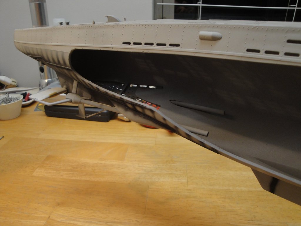
Major progress on the hull: the paint, or at least the first phase. As indicated before, I decided to go with Humbrol acrylic paints for the hull. These paints are getting a very bad rap on the Web and in the forums, because they are a far departure from the Tamiya and Vallejo paints. They are very thick, almost gooey in their appearance and require a significant amount of thinner to airbrush them. The good part is that they have the right color, that is very hard to find anywhere else. In retrospect, I should have used the enamel paints from Humbrol but decided to stay "green" as most as possible. The paints were ordered from Europe as they are not yet easy to find in the USA. The top of the hull requires the Matt 64 from Humbrol, which is one of the closest color to the Hellbrau used by the German. The bottom of the hull has been determined by a few Expert European modelers to be the following mixture: Two cans of Humbrol Matt 96, plus one can of Humbrol Matt 33 and one can of Humbrol Matt Black Green 40. Now, for the thinner, Humbrol recommend of course their own thinner. The problem is that it cannot be shipped to the USA. Therefore, I tried different mixtures before committing to the paint on the model: - Water....runs too much and makes the paint translucent almost. It would require a lot of layers which is not the easiest thing to do on such big hull. - Tamiya thinner..... Worked alright, but somehow, my airbrush clogged a lot. I suspect that the Tamiya thinner was not strong enough to thin the clumps of that very thick paint. - 70% alcohol ..... I suspect that this was too much alcohol and the paint was dry before hitting the surface. After searching the various foreign forums, I finally found the ideal thinner: Vodka! Yes, Vodka is 40% alcohol and mostly water. Some people are claiming that it works very well after a glass or two.... Not wanting to run to the local ABC store, I fortunately had a left over of 50% isopropyl alcohol and decided to use it. With about 35 PSI of pressure on my Paasche, the paint sprayed very well and did not cause many runs. Needless, to say, you need a very large bottle under your airbrush to contain 4 cans of paints and the equivalent in volume, of Vodka. The top portion of the hull was done first: A lot of masking has to take place: And finally: Now, I need to learn the skills of weathering and rust.... The Deck will be painted last, as it still needs a lot of work and details. Yves


- 760 replies
-
- 18
-
-
Yes, these type of Submersibles were really tight and small. The watching of Das-Boot movie will convince you of the almost inhuman conditions these poor sailors were enduring. Yves
-
Kevin, Fine soldering is an art form which has been lost to the Western world with a few exceptions. I collect brass train in O scale and most of them are hand soldered in Korea and sometimes in China. Japanese used to be good at this art form, but costs have taken the production of these models to Korea and Viet-Nam. It is extremely difficult and requires precise tools: - Gloves to insulate your fingers from the heat and to avoid staining the brass. - Resistance soldering unit for most small parts. - Iron for larger parts. - Torch for very big parts. Quite often it is necessary to build jigs and special fixtures to dampen the heat. It explains why these steam engines built by hand retails for more than $2K each and prices keep going up. I have used all the above techniques with various success and sometimes, I find JB Welding the best way to solder (Epoxy Glue) parts with success. I am not sure if you can find JB Welding in the UK, but it is basically a two tubes epoxy compound, with extremely small metallic flakes in suspension. The following link explains some of the phases of building a brass model: http://www.3rdrail.com/makebrass.htm Yves
-
Superb work on the hull. Quite a departure from the oversized plates of the old Matchbox mold. Yves
-
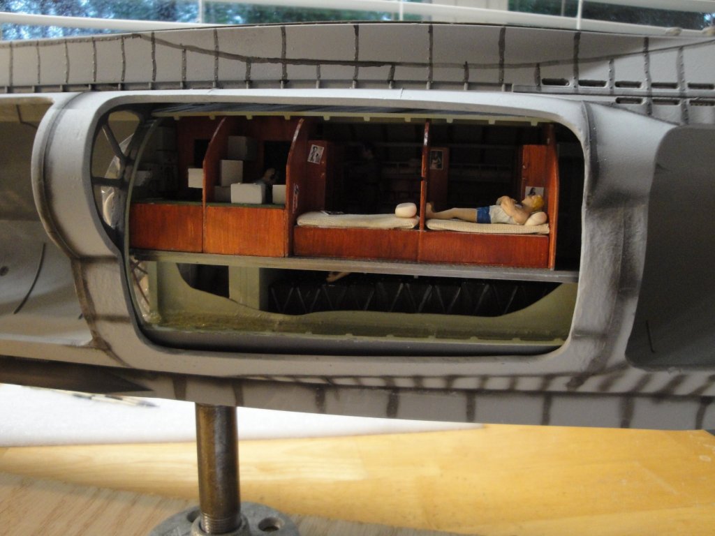
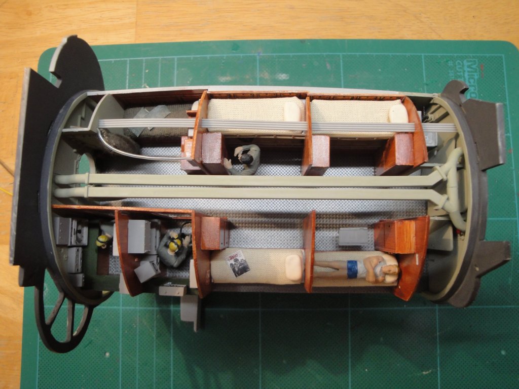
A couple more pictures of the recently completed module, in the hull: And an overall view: Yves

- 760 replies
-
- 18
-
-
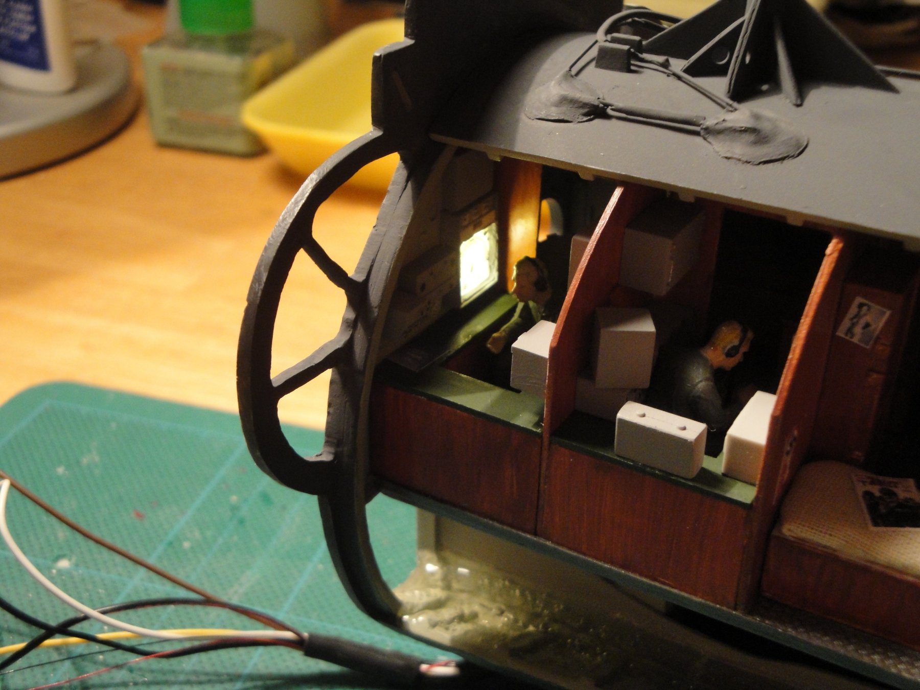
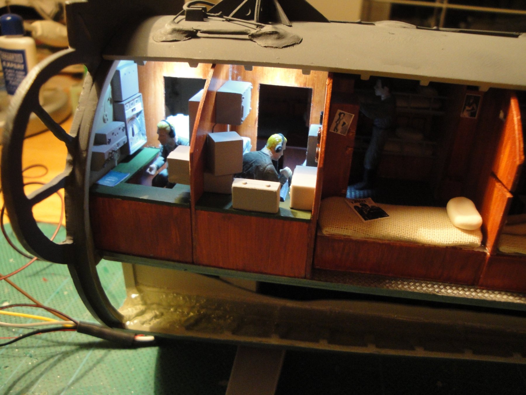
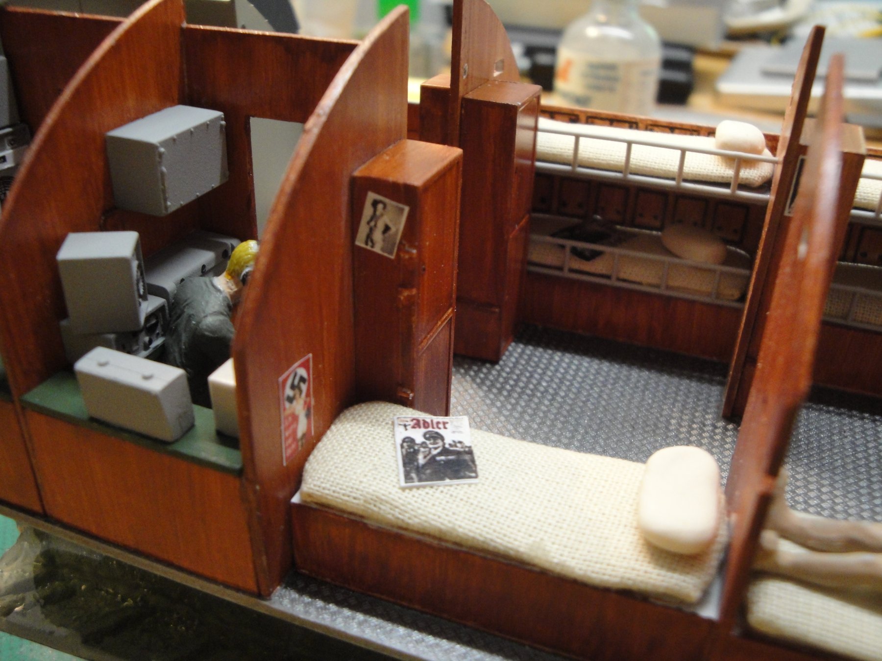
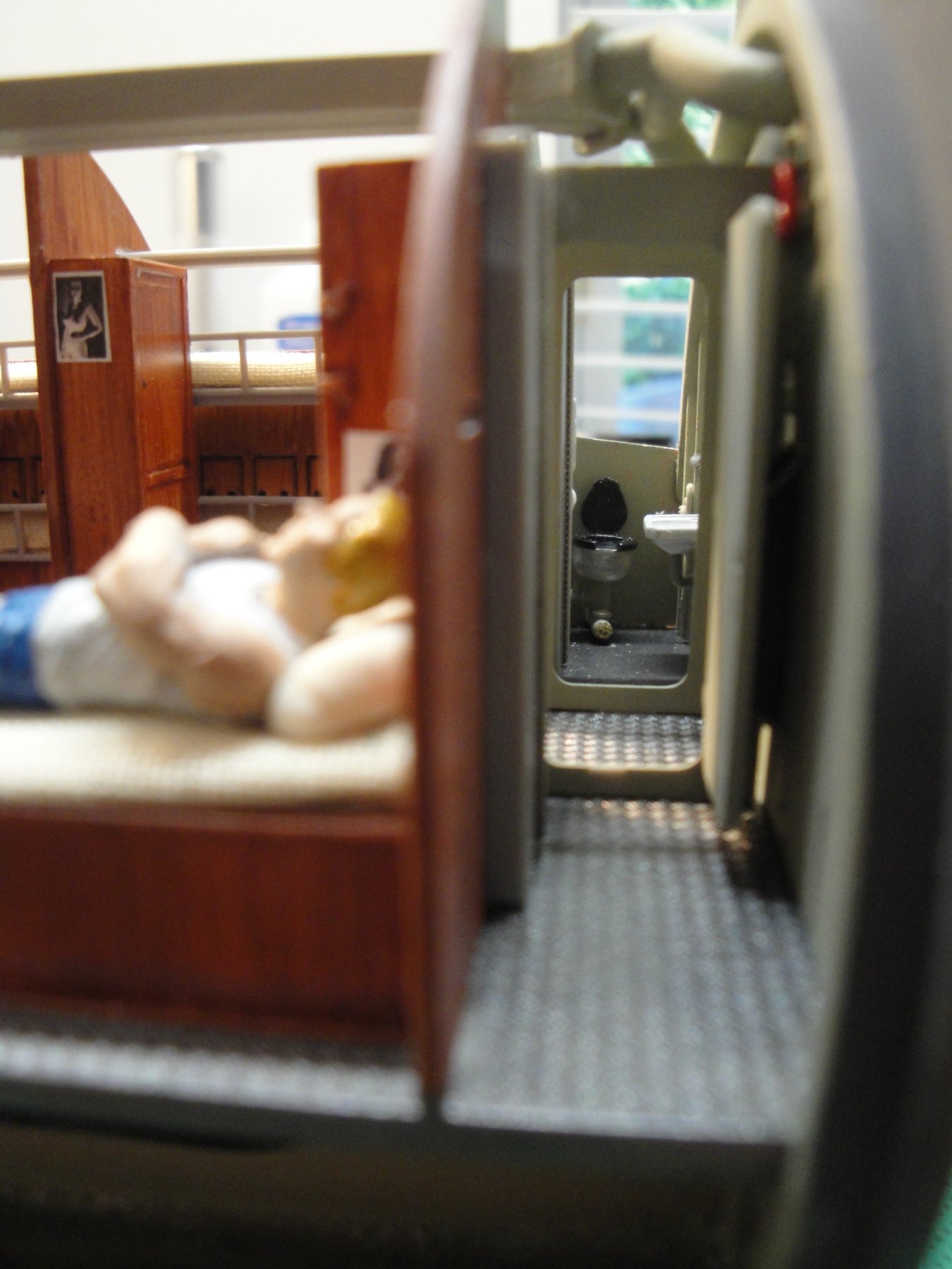
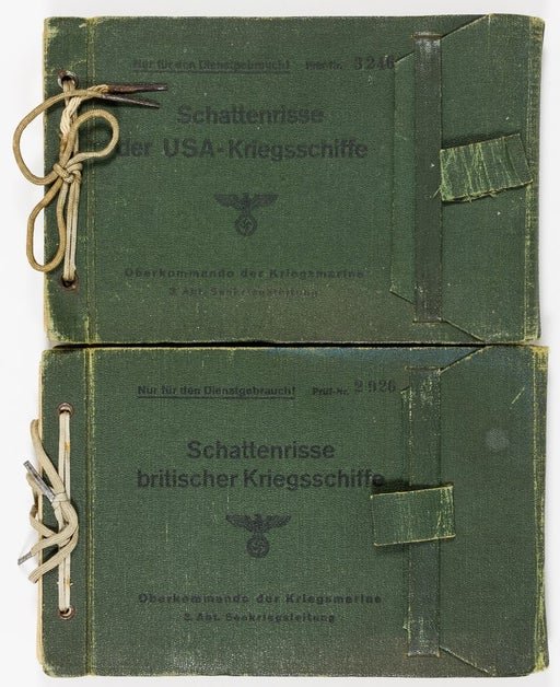
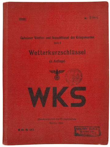
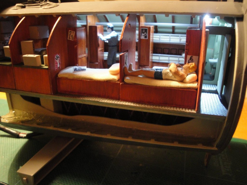
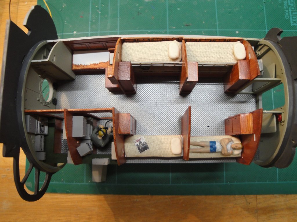
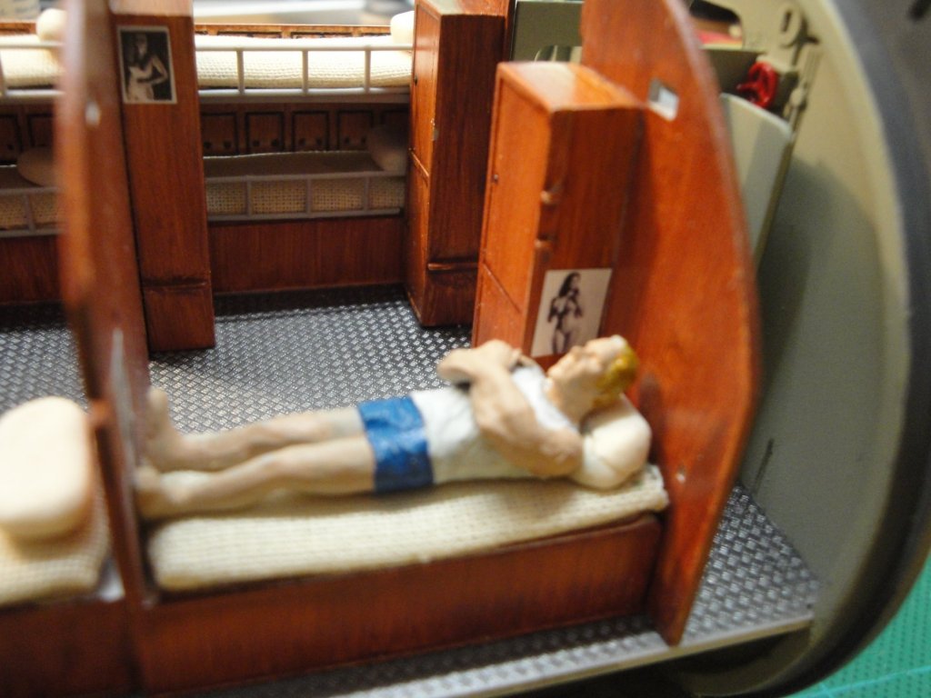
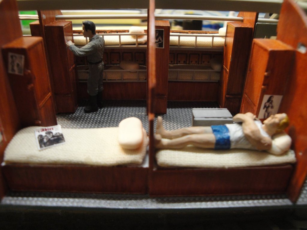
Yes, it is all WWII era German material approved by the Kreigsmarine 😉 On the desk of the Captain, is a 1/48th scale reduction of the following book, used to enter the Enigma codes: On his bed, are the two official U-Boot Target Recognition Manuals, specifically used while using the periscope or binoculars: For the girls, you can find them easily on the WEB as well as the Adler magazine: Thanks for all the encouragements and Likes!! Yves

- 760 replies
-
- 11
-
-
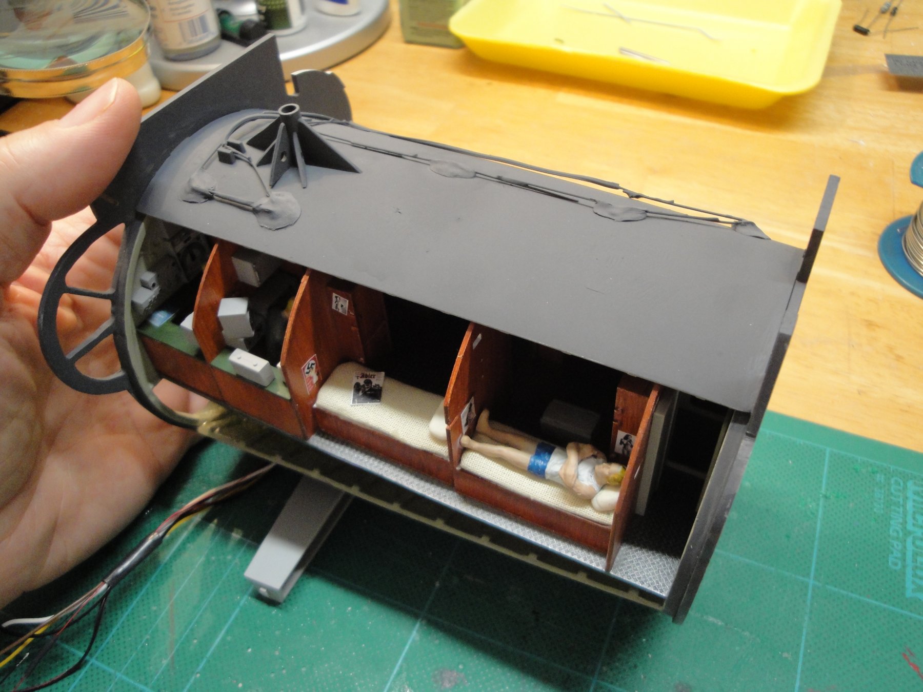
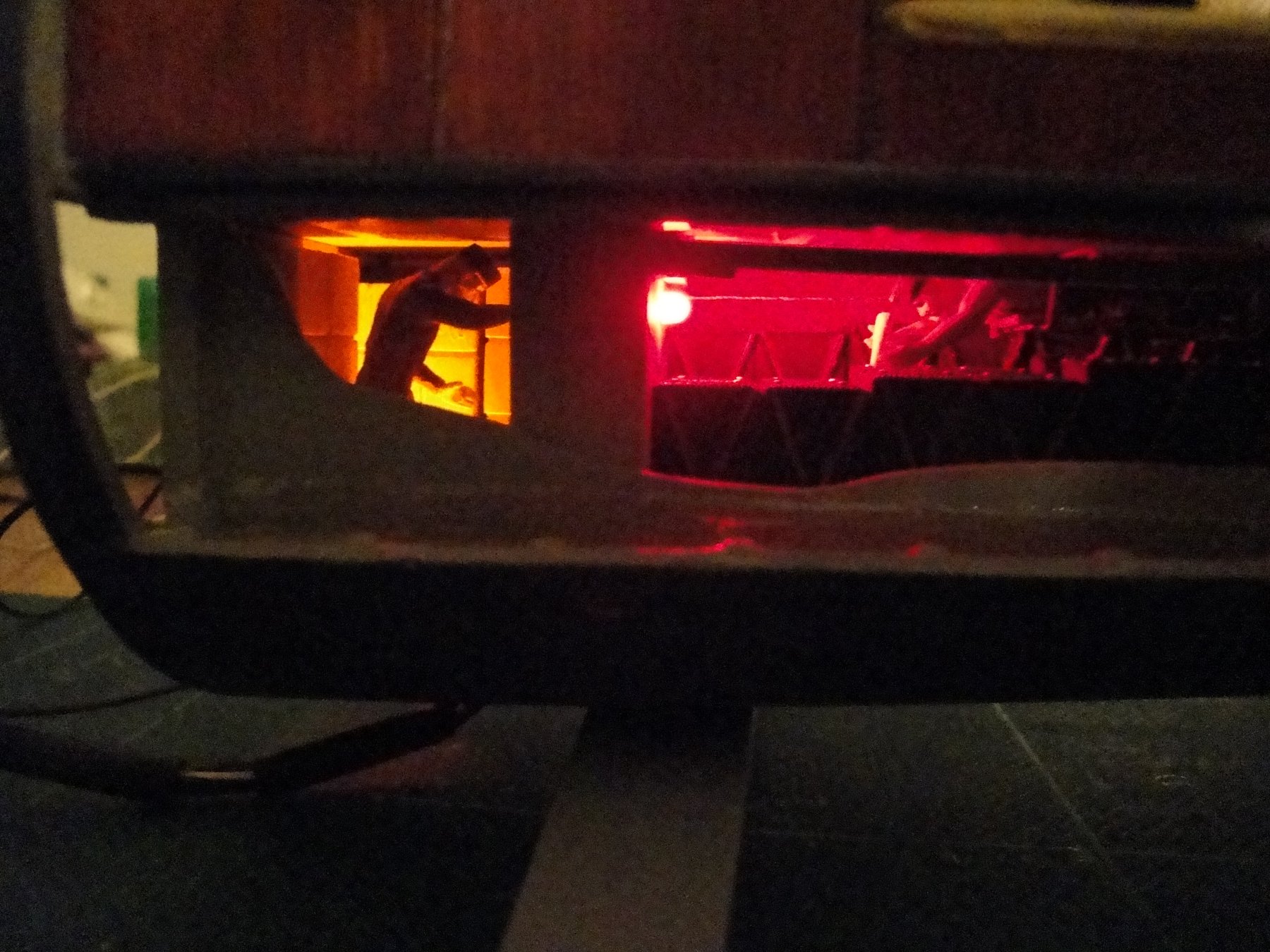
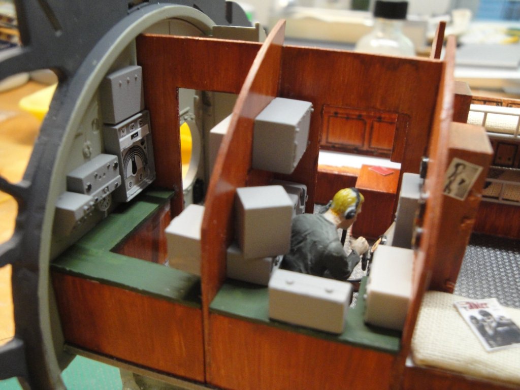
Module finished: The Radio equipment: The main lights: Radio and Sonar rooms lights: Batteries and Ammunition magazine lights: Yves


- 760 replies
-
- 23
-
-
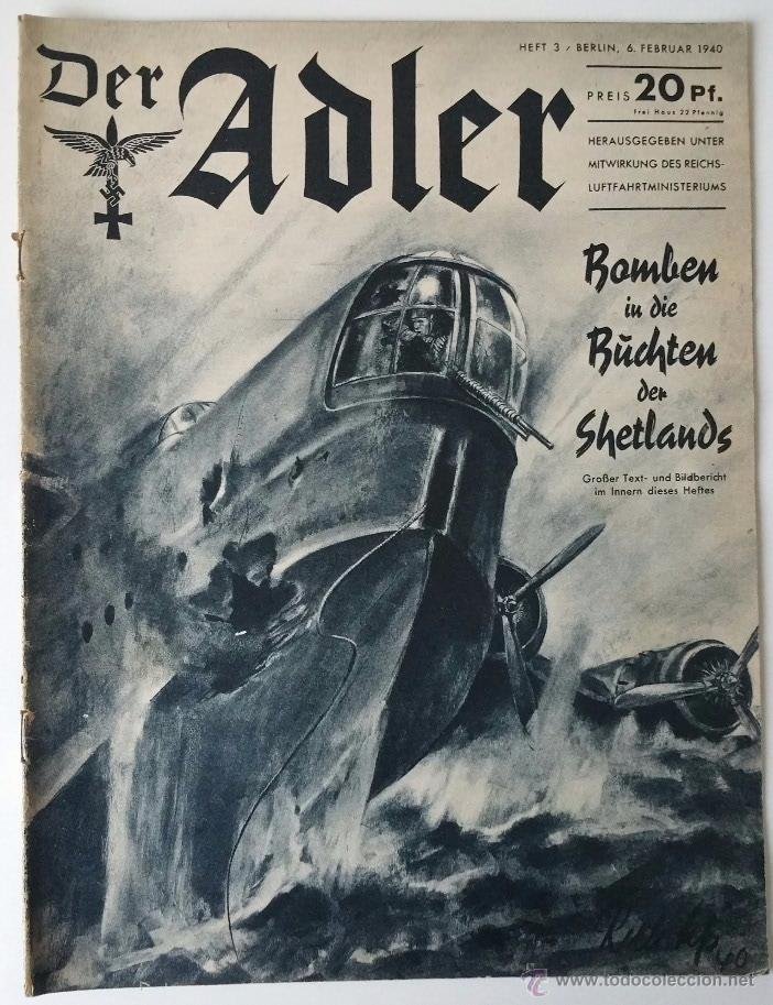
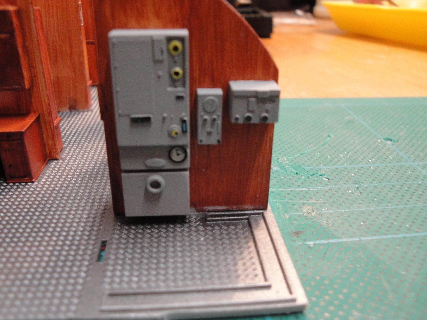
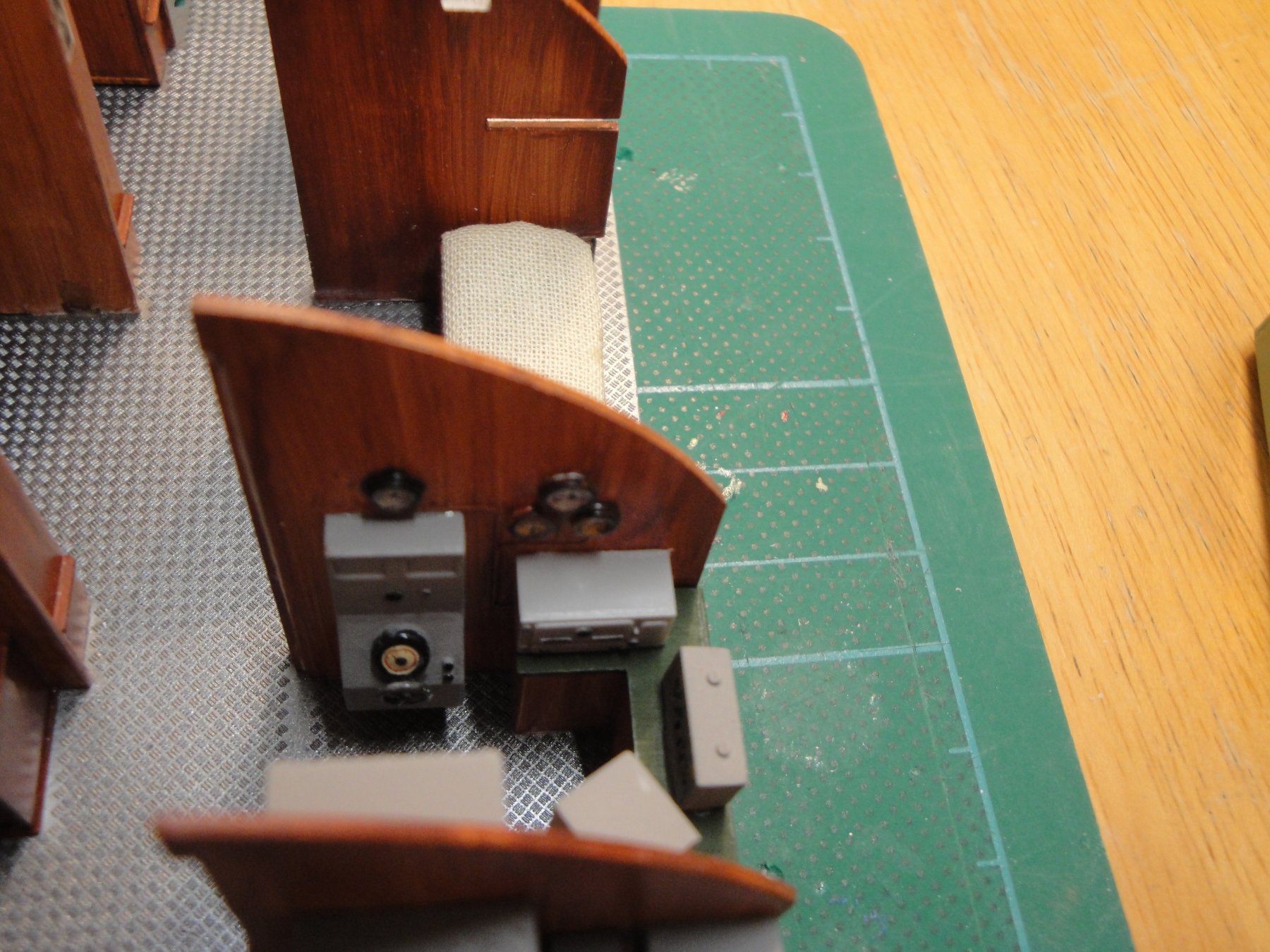
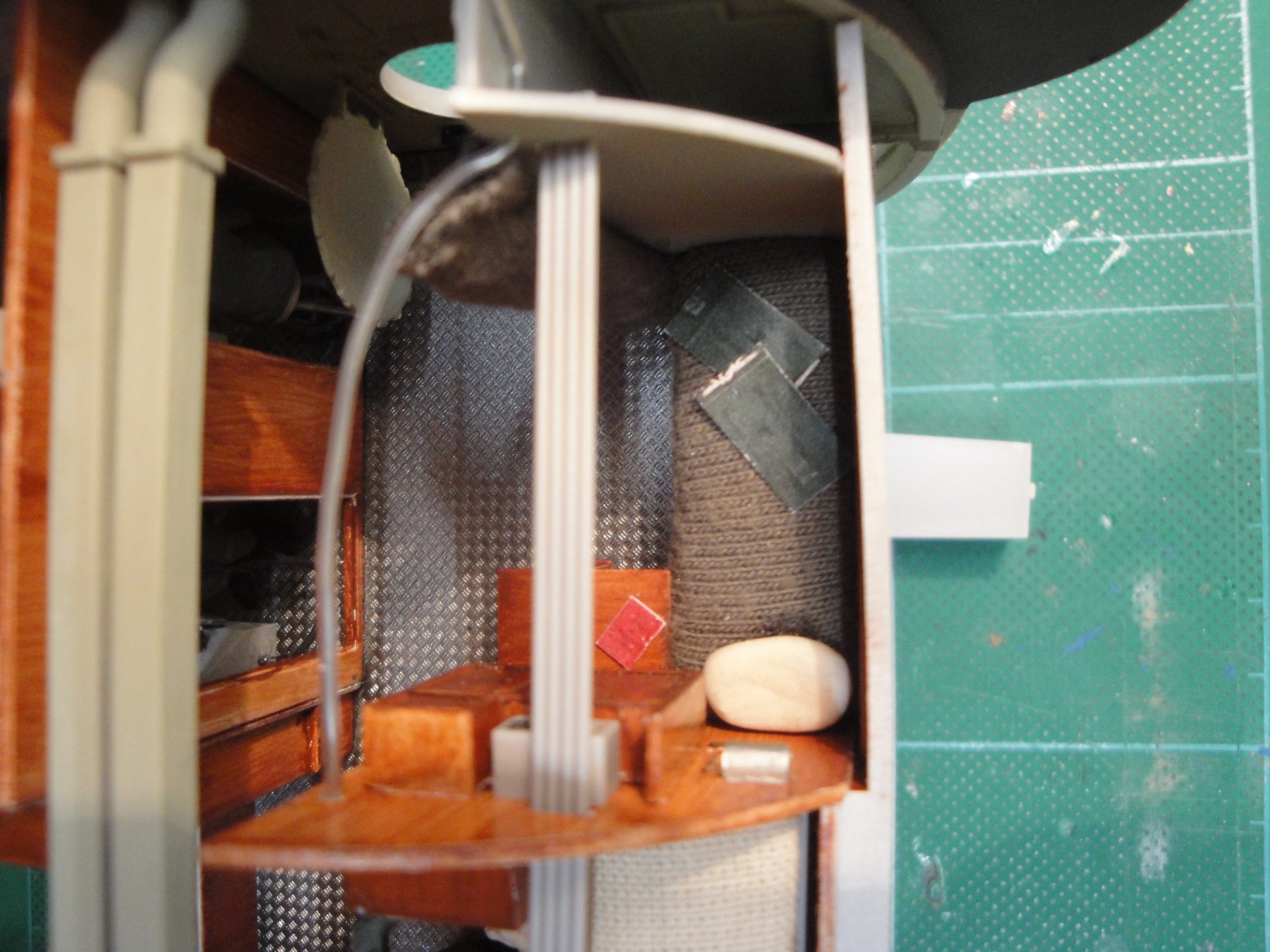
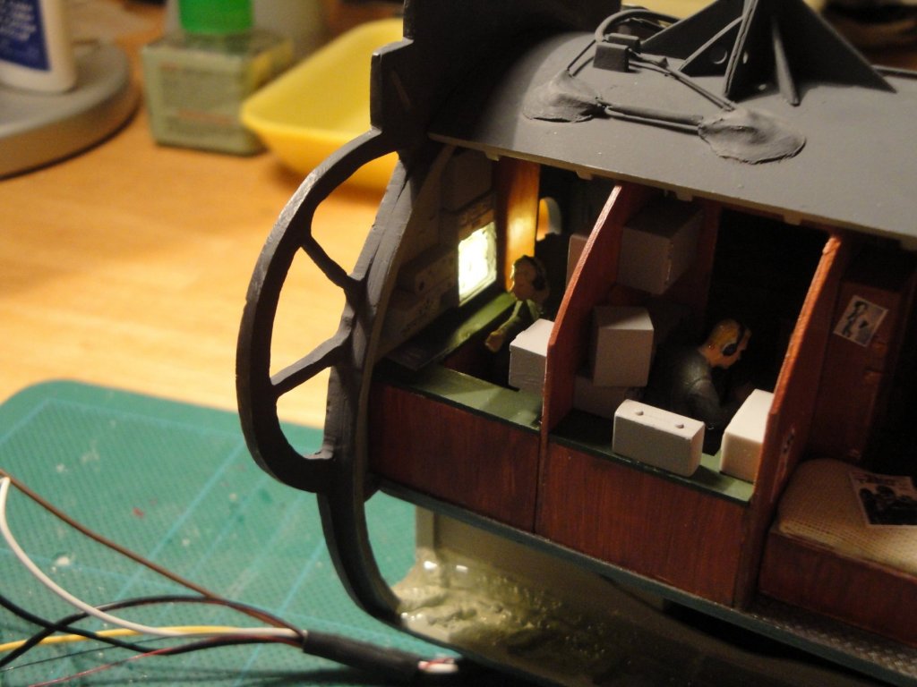
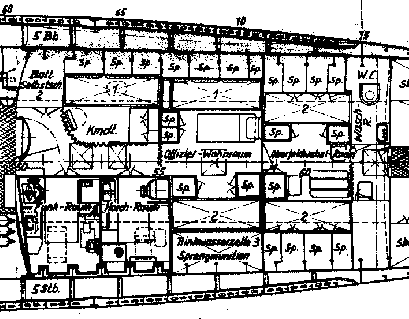
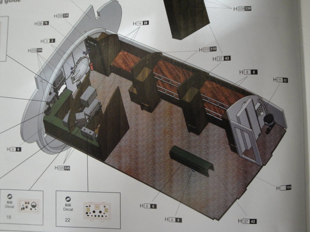
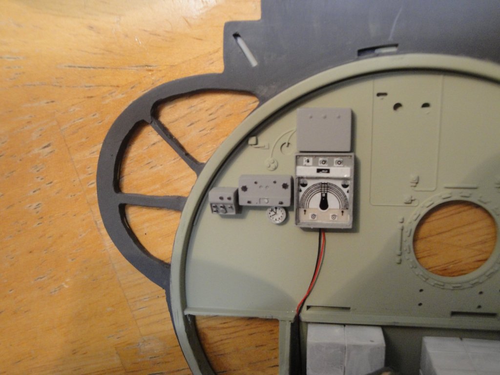
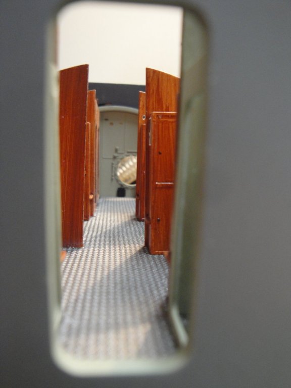
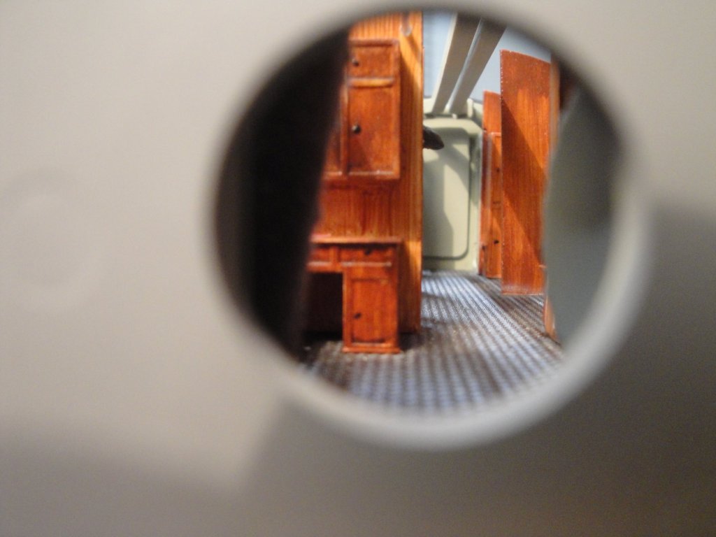
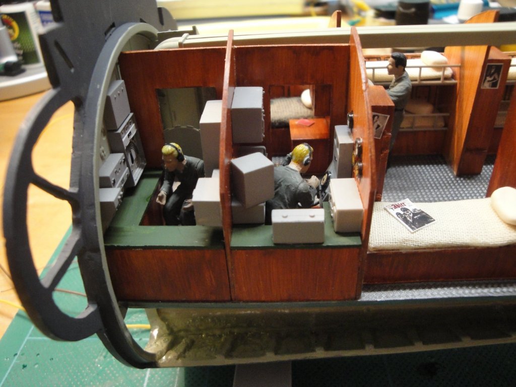
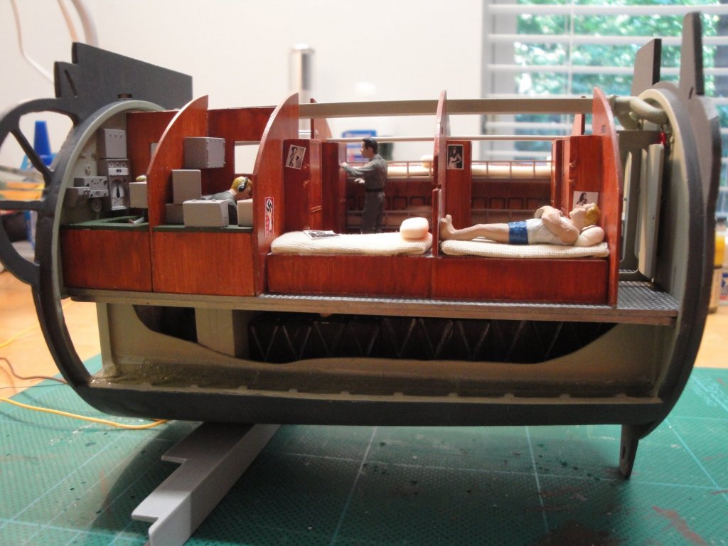
Finally, the Officer Quarter is almost finished. I was starting to run out of steam on this one.... The roof is the only part that needs to be glued but I wanted to leave it open so that I could show you the interior. I made two mistakes on this module, despite some improvements: One cabinet is not in the right location, but that was necessitated to allow the viewer to see more easily inside. The second one was by drilling a hole in the sonar equipment and destroying the micro-LED located inside. So, the Sonar screen no longer lites. I could not fix it....too many part to un-glue..... First, a recall of what the compartment should look like: The following is what is provided in the kit: As you can see, there is a lot of empty space and an oversized table in the middle of nowhere. Overall, it is quite a departure from the original blue-print. Therefore, using the extra parts I have, I decided to pimp up this compartment a little bit. Here are a few pictures of the construction phases: Radio compartment. As you may remember, because of my way of building that section, I have to allow the floor to slide between the two bulkheads. Therefore nothing close to the bulkheads can be assembled. Sonar compartment with the sonar screen (no longer working). Radio equipment. Micro-LED behind the large dial. Basically, the part is grind to open completely the screen, a clear piece of acrylic is glued and the decal is placed on top. The same was done on the sonar screen, with an unfortunate mishap. And now some views of the almost finished section: The captain quarter still needs to be detailed below: Captain Quarter completed: On the bed, two big binders published by the Kriegsmarine secret service, describing the characteristics and appearances of most known enemy ships. On his desk, the booklet containing the Enigma machine codes. The Captain had the only bunk with a curtain for some privacy. The location of his cabin was also across the hallway from the Radio and Sonar officers, for immediate response and actions. More views of the finished module: A piece of square styrene has been placed beneath the main floor to give it a more realistic look. I just cannot stand these flat floor provided by Trumpeter: they look so fake and unrealistic. I will be placing the roof soon, connecting all the electrical wires and call it a day, for that long and complicated module. Our next efforts will most likely be centered around the main hull, for a change. Yves


- 760 replies
-
- 19
-