yvesvidal
-
Posts
3,642 -
Joined
-
Last visited
Content Type
Profiles
Forums
Gallery
Events
Everything posted by yvesvidal
-
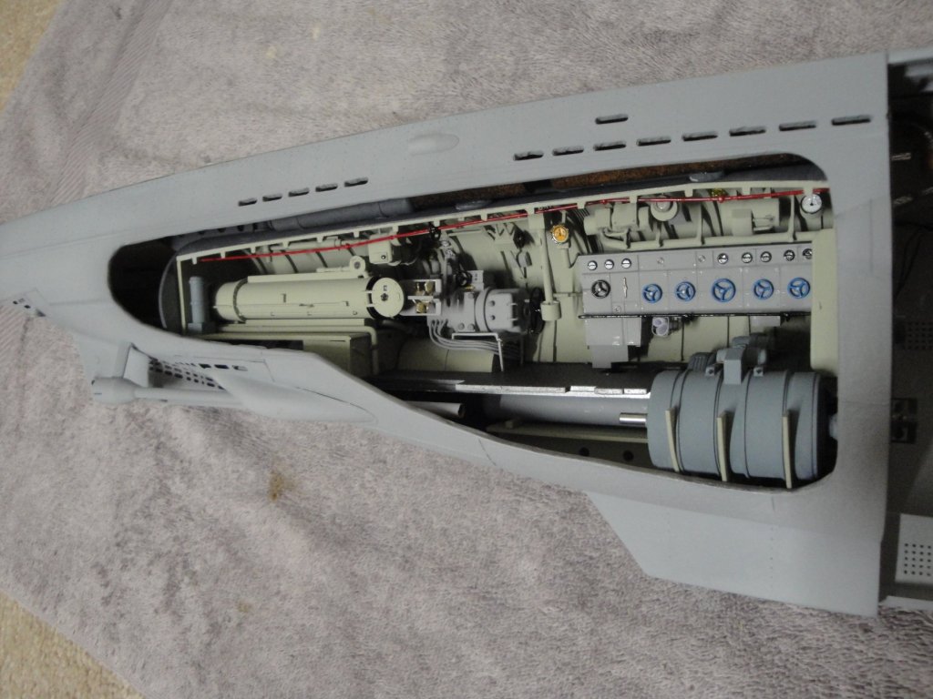
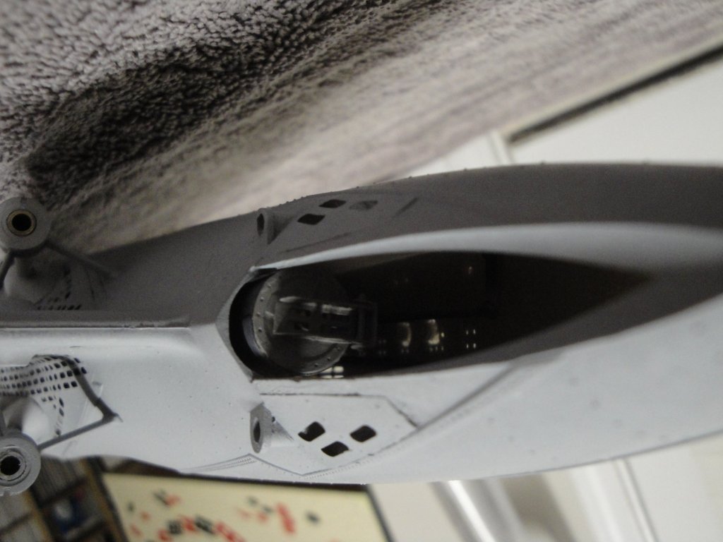
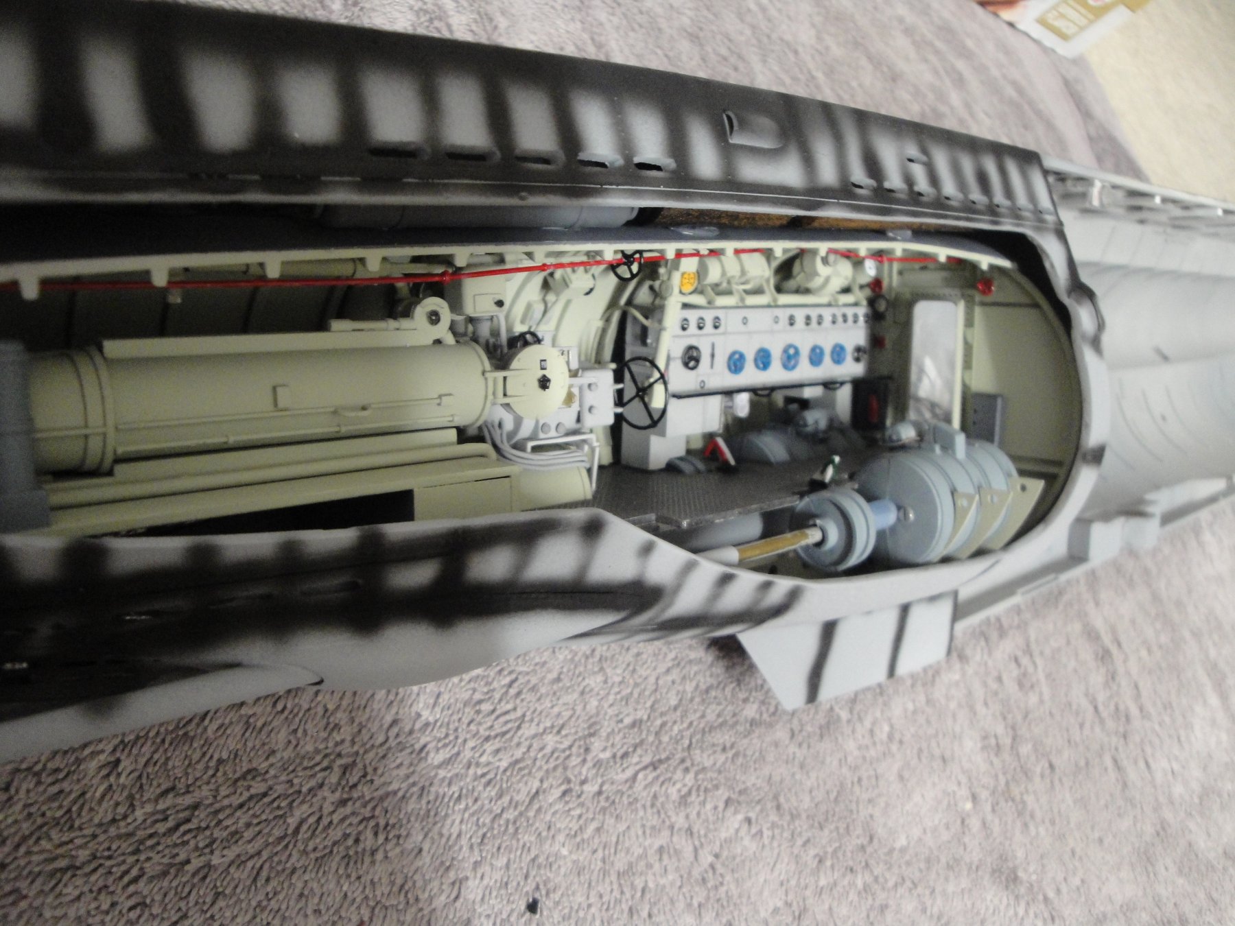
 Since I may be in a position to apply some paint in the coming weeks, it is important to prepare the other/transparent side of the hull: This is the cutout for the Diesel Engine room. I applied a coat of primer to better see any mistakes or imperfections. Once all the cutouts are done, I may do the oil canning masking, put the hull together and try to paint the whole enchilada. Yves
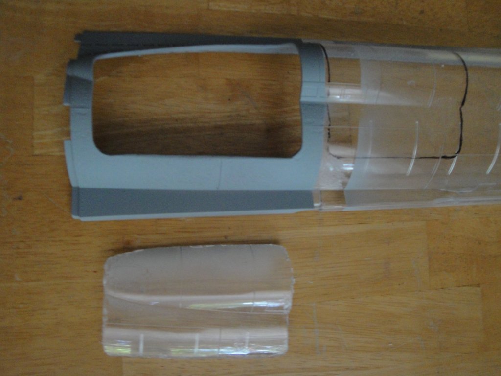
- 760 replies
-
- 10
-

-
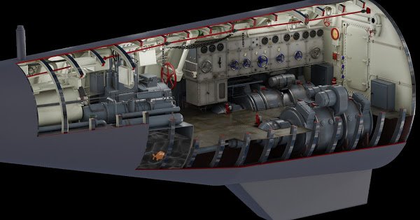
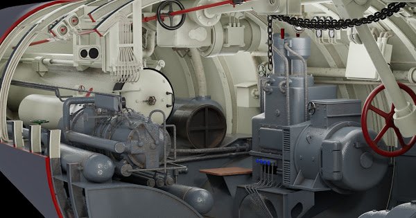
The Type VIIc submersible has always been an icon, especially for European modelers. Revell and numerous plastic kits manufacturers have been offering that model for decades and every new release is met with a renewed passion and interest. The same goes with 3D rendering and computer modelling of that submarine. I wanted to show you what incredible work was done by some passionate people to render the rear torpedoes compartment. Just looking at it, you can realize what Trumpeter could have done with their kit, by pushing a little bit further the limits of today's technology: Spectacular work, to say the least. Yves
- 760 replies
-
- 12
-
-
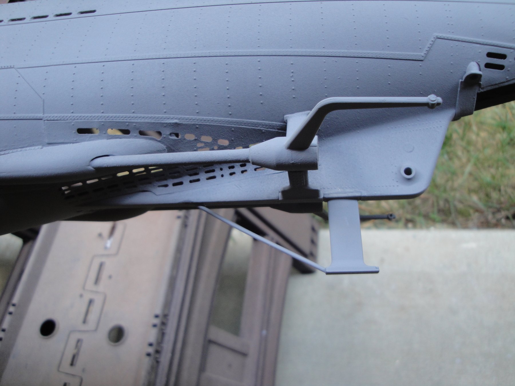
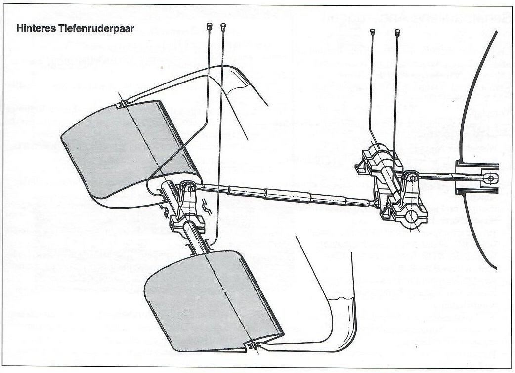
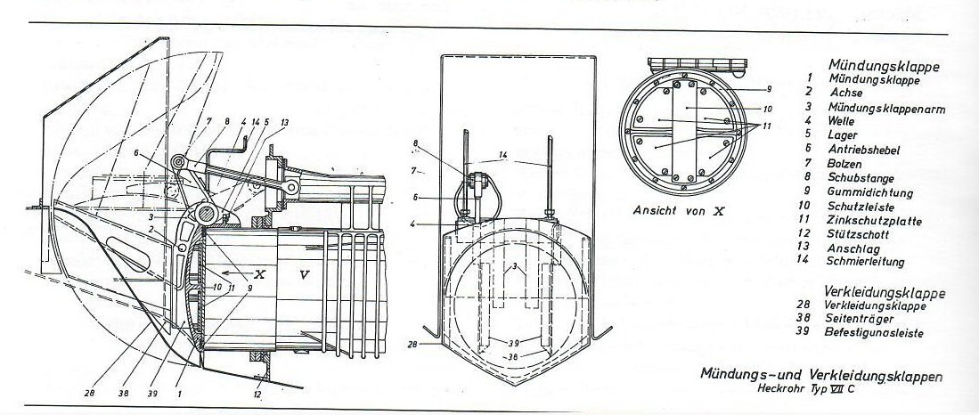
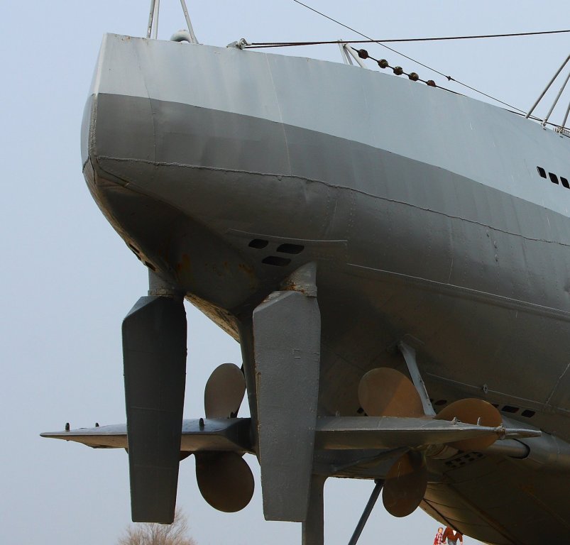
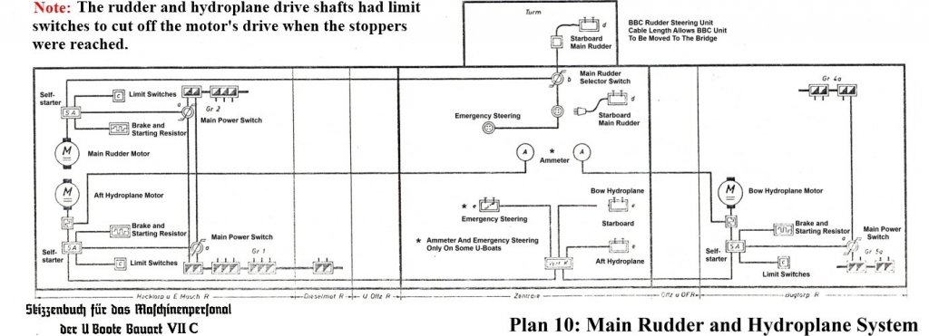
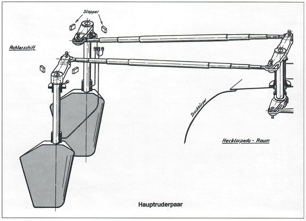
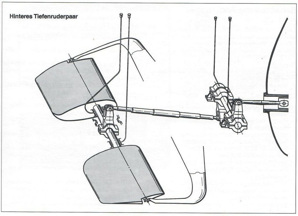
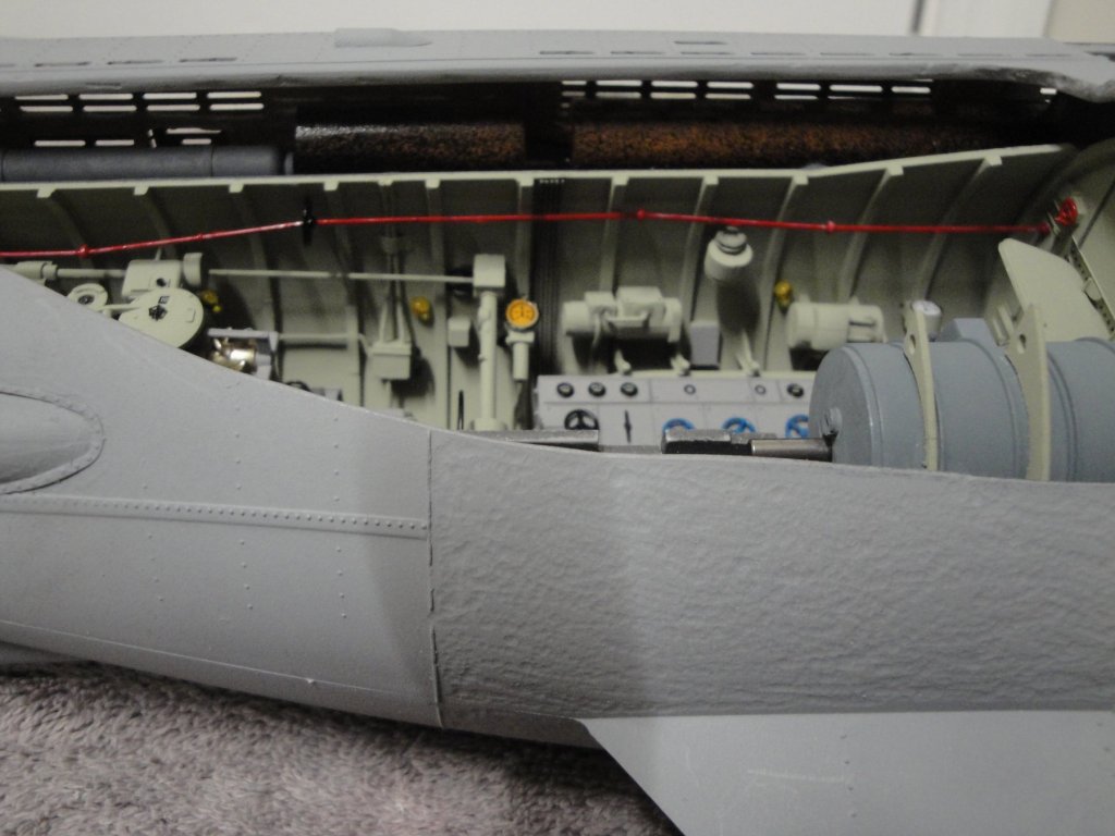
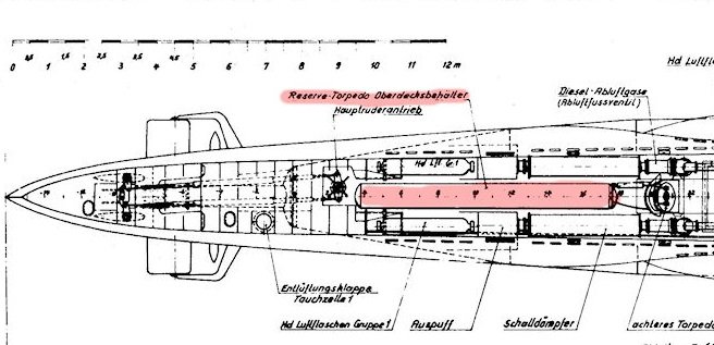
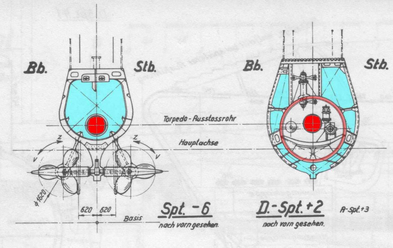
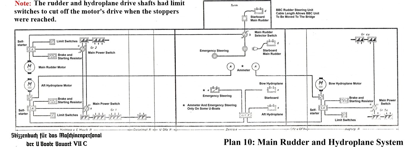
Coming back on the rudders and diving planes technology used by the German in their Type VIIc submersibles, and the stern in general: The picture above shows the famous U-995 sitting in Odela, Germany. Although this machine has been extensively modified throughout its career, it gives us a very good idea of what Type VIIc were during the war. Above the propeller shafts, you can see a ring attached to the hull: this ring was used to tie some ropes and allow maintenance crew to inspect and clean the propellers under water, in case of fouling or being tangled in nets or cables.. It was also used in Drydocks to help the repair folks. I should add that little detail to my model. Similar rings are also available on the diving planes. On the U-9995, the rear torpedo tube has been sealed. This is open to the public and they did not want kids to crawl inside the tube and fall outside. Therefore, the entire rear section has been welded with a steel plate, between the rudders. This drawing shows some cutouts of the stern and gives some dimensions about the propellers and rudders. You can see that the propellers are not directly blowing the rudders but they do it for the diving planes. Obviously the stern was not wide enough to allow the rudders to be in line with the shafts. The flow of water pushed against the stern is most likely very sufficient to provide some nice steering actions. On the second cutout, the storage area under floor calls for two torpedoes. The Trumpeter kit has only room for one, between the electric motors. The pressure hull in red is also visible with the steering mechanism on top. The last drawing gives you the electric/logic schematics of the rudders and diving planes (stern and bow) and how they were controlled from the command section, in the middle of the submersible. It is always good to know more about the technical details of the models we are building, don't you think? Yves

-
That model of the USS Rasher is truly impressive of details and accuracy. This is also a much bigger boat that the Type VIIc. Yves
-
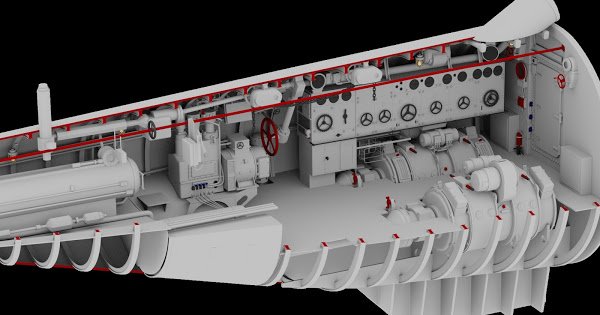
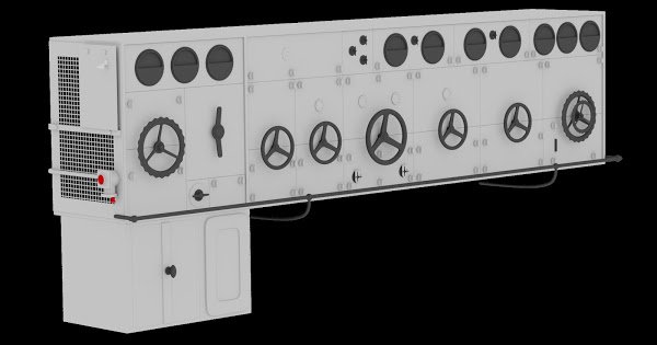
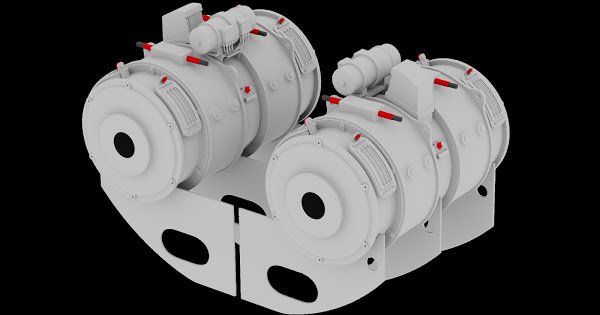
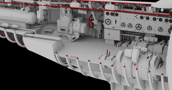
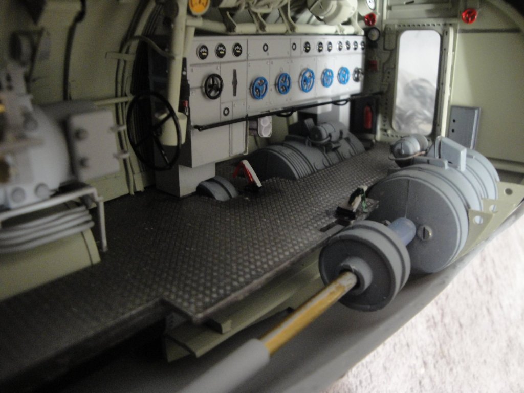
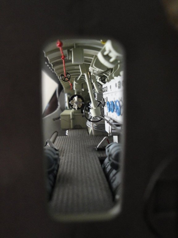
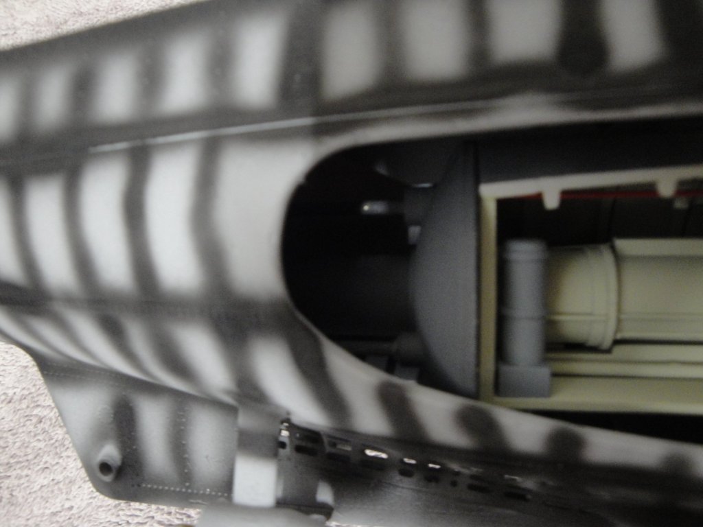
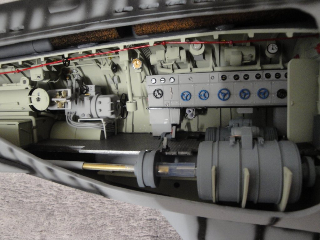
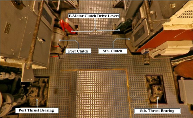
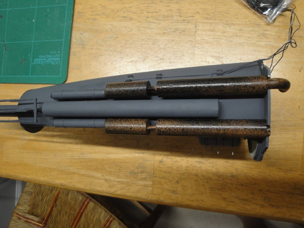
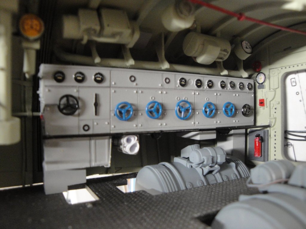
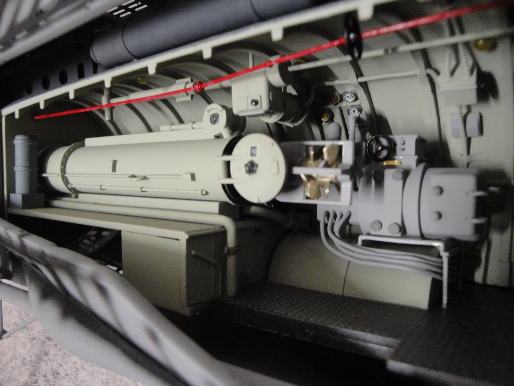
Final details inside the rear compartment, the shaft brakes. This device was completely omitted by Trumpeter and that is a pity as it brings an interesting element to the understanding of how a submarine was operated. The Shaft brakes were located between the electric motors and the clutches to the propellers. This way, it was possible by stopping the motors, opening the clutches, locking the shafts and re-engaging the clutches to prevent the propellers from spinning. There are of course two brakes, one for each shaft. The following views clearly show where they were located with respect to the motors and shaft main bearings and their respective colors as painted on the U-995 on display (most likely, these were not painted this way during the war). Finally, some pictures of the rear compartment in the hull, with the shafts connected to the electric motors. I will have a to find a way to disguise that ugly piece of tube.... Above, you can see the two brakes added to the floor of the compartment. Close-up on the pressure hull end (courtesy of RCSUBs - 3D printed). This is bringing a conclusion to that rear module. I will populate it with a few sailors, at a later time. Yves


.thumb.jpg.aa132741a0a074bbff6b601ab9b40f51.jpg)
.thumb.jpg.0ec461d311f87d8ebacdeea4091f90af.jpg)
- 760 replies
-
- 20
-
-
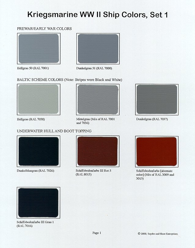
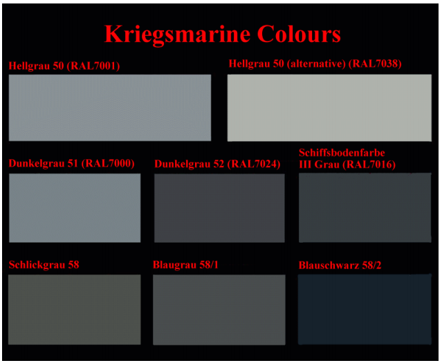
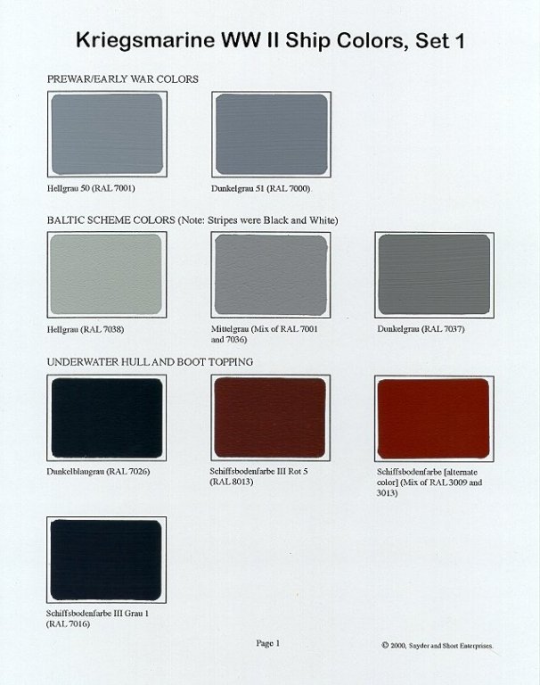
Colors, colors. Let's talk about U-boot colors. First of all, the correspondence of colors given by the Trumpeter chart is less than precise and sometimes totally arbitrary. So, it is not a good reference. More information can be found in the pamphlet written by Dougie Martindale, which is a fantastic mine of information and the result of years of intensive research on the subject. The following are excerpts of his excellent treatise on the U-Boot subject: "Kriegsmarine U-boats were painted in two greys. The first grey was painted on the conning tower and the upper hull (above the waterline). The second darker anti-fouling grey was painted on the lower hull, below the waterline. The horizontal division between the two greys took place just below the free-flooding holes on the hull. Early pre-war boats had this division line slightly lower than was common during the war. Some pre-war original Type VII boats (also known as VIIAs) had the tops of their saddle tanks painted in the upper colour, but most Type VIIs had the whole of their saddle tanks painted in the lower anti-fouling colour. Contrary to many illustrations in numerous publications, there was no bootline/boot-topping (the dark grey horizontal stripe between lower and upper waterline) on U-boats; these were only applied to surface units. The steel horizontal surfaces at the extreme bow and stern were either painted in the upper lighter grey or black. The wooden deck was coated with a wood preservative, and shall be discussed later. A number of side profiles, drawings and illustrations show U-boats with red lower hulls and black bootlines, and these have sparked countless debates within the modelling community. Many commentators maintain that no U-boats, either before or during the war, ever had red anti-fouling paint beneath the waterline. Another opinion is that at the very start of WWII some U-boats had red lower hulls, but at the next dry-docking they were painted dark grey. Other opinions hold that while some prewar boats may have been red, all wartime boats were dark grey. In the book Die Deutschen Uboote Geheim 1939-1945 (German U-Boat Secrets 1939-1945) by Richard Lakowski (Brandenburgisches Verlagshaus, 1997), there are two editions of the building regulations form Nr. 31, which specifies the application of paints upon U-boats. These can be found at: http://www.u-boot-archiv.de/dieboote/farben_maerz_1940.html http://www.u-boot-archiv.de/dieboote/farben_juli_1944.html The March 1940, November 1941 and July 1944 editions of this building regulation all state that the external sections of the lower hull were to be painted with two coats of anti-corrosion paint followed by one coat of the anti-fouling dark grey paint Schiffsbodenfarbe III Grau (DKM 23a, literally “ships bottom colour 3 grey”). This was called Wasserlinienfarbe W.L. III Grau (literally “water line colour W.L. 3 grey”) in the first two editions, but as previously mentioned this was exactly the same paint as Schiffsbodenfarbe III Grau. Finally, another coat of Schiffsbodenfarbe III Grau (DKM 23b) was to be applied. 23b was exactly the same paint as 23a; the letters were used to specify that two coats were to be applied. There is no mention anywhere in these regulations of Dunkelblaugrau (RAL 7026), which is included in the Snyder & Short paint chip cards and White Ensign Models’ KM paint range (Colourcoats KM03). The wartime painting regulations are thankfully available to us, but the pre-war painting regulations are, unfortunately, not in common circulation. These pre-war regulations would likely have shed light on the question of whether red anti-fouling paint and dark grey bootlines were applied to prewar boats at any stage. It is especially regrettable because in black and white photographs it is impossible to distinguish with any degree of certainty between a red and a dark grey hull. Since the U-boat arm had been experimenting with the colours above the waterline in the years leading up to the commencement of hostilities, could it have been possible that they also experimented with the colours below the waterline? A comment by U 35 veteran Kurt Grosser suggests to me that colours other than dark grey were used in pre-war times. He maintains that when he reported aboard U Kriegsmarine U-Boat Colours & Markings The Wolf Pack: A Collection Of U-Boat Modelling Articles Page 22-35 in April 1939 the lower hull of this U-boat was dark green. We should be extremely careful when dealing with veterans’ memories of the colours used 60 to 65 years ago, but this comment is interesting in light of the fact that a green anti-fouling paint - Schiffsbodenfarbe I Grün (DKM 24a and 24b) - was mentioned in the 1944 painting regulations. Wartime upper greys Immediately prior to the war, the most common scheme within the U-boat fleet consisted of Dunkelgrau 51 on the upper hulls and towers. Very soon after the start of hostilities the Dunkelgrau 51 paint on a few U-boats such as U 30 was replaced by Hellgrau 50. Over the course of the winter of 1939, the Hellgrau 50 paint gradually became as common as Dunkelgrau 51. Many of the U-boats which were completed in 1940 (such as U 69, U 94, U 99 and U 552) sported this light grey Hellgrau 50 colour when launched. The contention by some that most wartime U-boats were the light grey Hellgrau 50 is wholly inaccurate, as both Hellgrau 50 and Dunkelgrau 51 were commonly used upon wartime U-boats. The common use of both these colours is supported by the well-researched 3-part decal sheet by U.L.A.D.- decal for the Revell 1/72nd Type VIIC U-boat kit. Another colour which was commonly used was Schlickgrau 58. Blaugrau 58/1 and Dunkelgrau 52 were much less common, and Blauschwarz 58/2 was hardly used at all. According to Randy Short of Snyder & Short Enterprises, Blauschwarz 58/2 was not used at all upon Type VIIs. Dunkelgrau 53 was used in camouflage patterns, but was rarely (if at all) used as a sole upper colour. It would have been somewhat helpful if the painting regulations had stated which of the Kriegsmarine paints were to have been used upon the upper hulls and conning towers of U-boats. Unfortunately they don’t, and so are of limited use to us. The painting regulations stated only that shipyards had to ask the High Command for instructions on painting the upper colour of each individual boat, and that the U-boat’s planned operational area would often influence the shade of grey used. The latter does help us with the boats which served in the Arctic and in the Mediterranean, and shall be discussed shortly. The regulations offer absolutely no help to us on the question of which of the three most common colours - Hellgrau 50, Dunkelgrau 51 or Schlickgrau 58 - was used on boats serving in the Atlantic or training in the Baltic. All we can do is attempt the difficult and often frustrating task of photographic interpretation. It is very difficult to differentiate between Hellgrau 50 and Dunkelgrau 51 in black and white photos where no reference point is available. In general terms, the Hellgrau 50 paint looks very light – even white – in photos where the sun is shining upon the surface in question. Dunkelgrau 51 can look light when there was a lot of light present in the photograph, but does not ever look white like the Hellgrau 50 sometimes does. For modellers attempting to determine whether their chosen subject was Hellgrau 50 or Dunkelgrau 51, it is advisable to study photographs of warships where these colours are known to have been used (as previously mentioned the superstructures of pre-war and early wartime vessels were Hellgrau 50 and the upper hulls were Dunkelgrau 51). Although a marked contrast between these colours can be seen in photos of Kriegsmarine warships, it is still very difficult – sometimes impossible to distinguish whether one or the other was used on a U-boat merely by photographic interpretation. Such an exercise is often extremely frustrating and highly subjective. One factor which may have caused some confusion regarding U-boat upper colours is the name of the Dunkelgrau 51 paint itself. Although “dunkel” means dark, the paint was very far from a dark grey. It wasn’t even on the darker side of medium grey. As the above photo above shows, if anything the so called “Dunkelgrau 51” was on the lighter side of medium grey. The Dunkelgrau 51 name is therefore a misnomer. Many modellers, of course, have assumed that Dunkelgrau 51 was dark grey. In thinking this, they would next think that the upper colour in U-boat photos could not possibly be the “dark grey” Dunkelgrau 51. Rather it must be the light grey Hellgrau 50. Others do know the true shade of Dunkelgrau 51 from paint charts. But the “Dunkelgrau” name can still exert influence, leading to a preference for Hellgrau 50. Over the years many modellers have chosen a light grey paint for their upper hull on their U-boat models. One could argue that the medium and dark grey colours have not been chosen frequently enough. Furthermore, a good case could be made that U-boat upper colours were often darker than many enthusiasts have realised. This is particularly true of the mid to late war period, when light grey upper colours were less common. For those who still hold that the light grey Hellgrau 50 paint was “standard” on U-boats, let us refer to the painting regulations. The March 1940 edition states that either Dunkelgrau 51 or Schlickgrau 58 were to be used; the November 1941 regulations and the July 1944 regulations both state that Schlickgrau 58 was to be used. We remember that the shipyards had to ask the High Command for instructions on painting the upper colour of each individual boat, so in practice there were a few paints to choose from. But the two paints specifically mentioned in the regulations did not include Hellgrau 50. The light grey Hellgrau 50 was certainly commonly used, but equally certain is that this paint was not the “standard upper colour”. As well as the High Command, it is quite likely that the commanders and the bosses at the shipyards would also have had an influence over which upper colours were used. Such individuality between boats can be illustrated with U 47 and U 99. Both these famous U-boats served in the Atlantic, were based at Lorient toward the end of their careers, and were sunk in March 1941. The upper colour of U 47 was Dunkelgrau 51 until the summer of 1940, when it was changed to a darker shade that may have been Schlickgrau 58. U 99, on the other hand, was Hellgrau 50 throu ghout its illustrious career.This was perhaps because at the time U 47 was launched Dunkelgrau 51 was the prominent colour, and when U 99 was launched it was more usual for Hellgrau 50 to be used at the Germaniawerft shipyard. We should remember that U-boats often sported different colours at various times. Even boats that sailed from the same Atlantic base on every patrol were subject to paint colour changes. There are a multitude of possible reasons for these changes. A lack of availability of a particular paint at a certain time, the preference of a new commander for a camouflage scheme, or a change of operating base could all be potential reasons. In the case of the U-boats serving in the Mediterranean, the theatre of operations did make a difference since it was commonplace for camouflage to have been used in that area. The same can be said for the Arctic, where conning towers were sometimes painted white. U-boats operating out of Norway sometimes had the upper half of the conning tower, above the spray deflector, or all of their conning tower, painted white. This was intended to allow the boat to blend in better with the sea mists and fogs that often hang close to the surface of the water in high latitudes. A number of colour photos of the school U-boats based at Gotenhafen in the winter of 1941/42 show all of the upper colours to be the same dark grey colour. All these boats were a dark grey that may have been as dark as the lower hull grey. A colour shot of U 595 in Danzig in the early months of 1942 shows that this boat had a darkish grey upper colour at that time. Another colour shot, taken in Drontheim in perhaps 1942, shows all of the U-boats with the same dark grey upper colour. The majority of U-boat models have a light grey upper colour, with some painted with a medium grey. But as many photos show, modellers should not shy away from painting their model with a dark grey upper colour." Dougie Martingale studies goes a lot deeper in the subject, but that should suffice to realize that we need two colors for that specific model. Now, to find them.... Another sampler of Kriegsmarine colors: Yves
- 760 replies
-
- 13
-
-
Any new updates on that fantastic kit? Yves
-
Greg, Most likely I will be doing a light weathering based on your explanations (I learn from you a lot) but I am not ready for the major stuff like hairspray and chipping fluids. Thanks for following my project, it means a lot coming from you. Yves
-
Amazing of beauty, precision and realism. You are a Master with PE and plastic kits. Yves
- 345 replies
-
- 5
-
-
- graf zeppelin
- trumpeter
- (and 2 more)
-
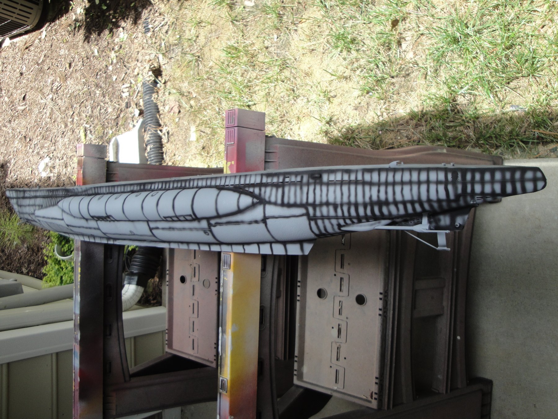
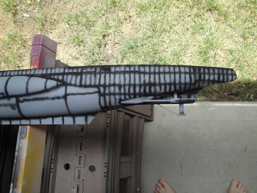
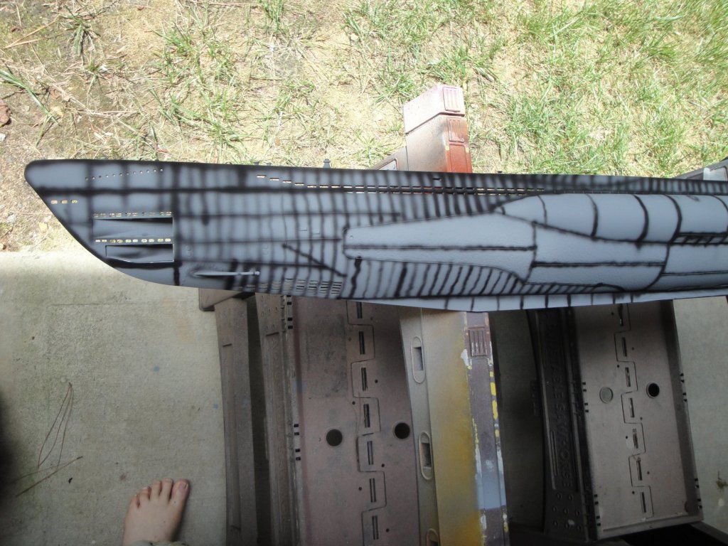
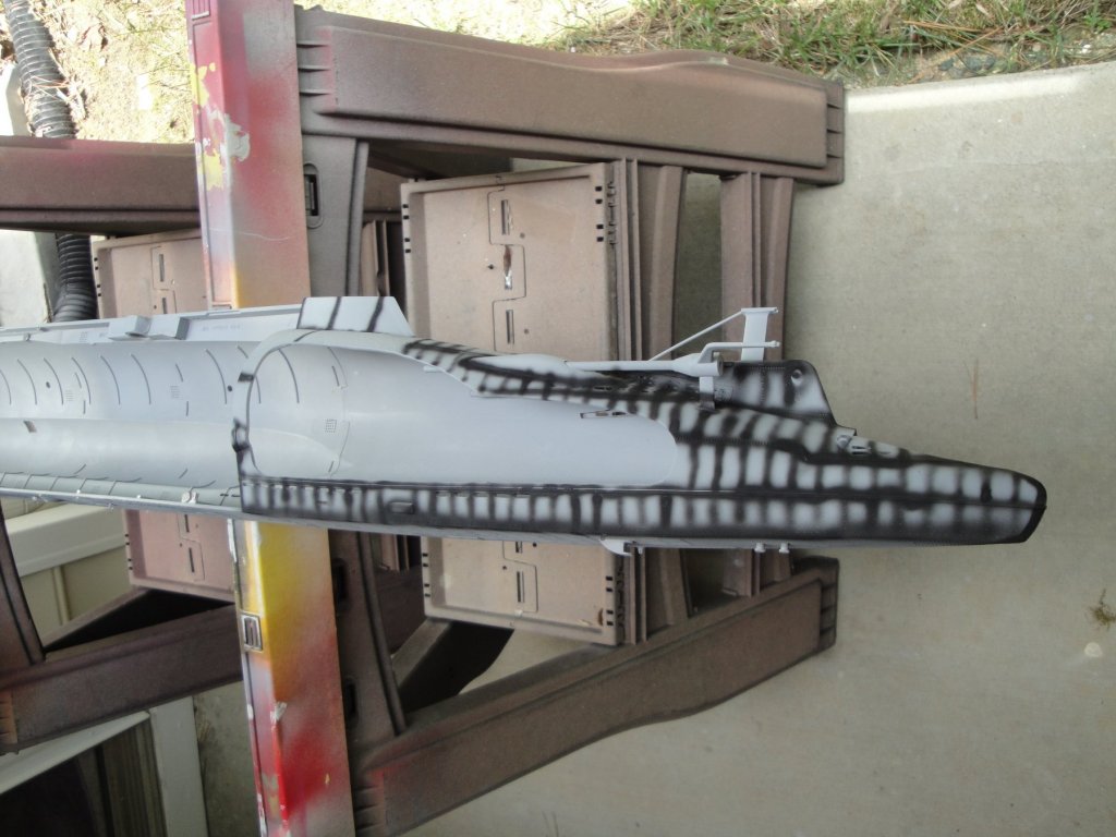
My first attempt at oil canning. I am trying to learn from the experts but this is a big hull and sometimes my fingers cramp on that dual action airbrush. Plus it is 94 outside and besides drying the paint, it does not help me: If it is too bad, a coat of primer and we are back to Square 1. Yves

- 760 replies
-
- 12
-
-
The pine will likely warp. Not sure about Premium quality, but I am done with those pine boards from Lowe's or Home Depot. You will have to treat it (varnish) to minimize the risks. YVes
-
Great effects with the LEDs. Glad you went with warm white/yellowish color. Yves
- 337 replies
-
- 4
-
-
- finished
- mountfleet models
- (and 1 more)
-
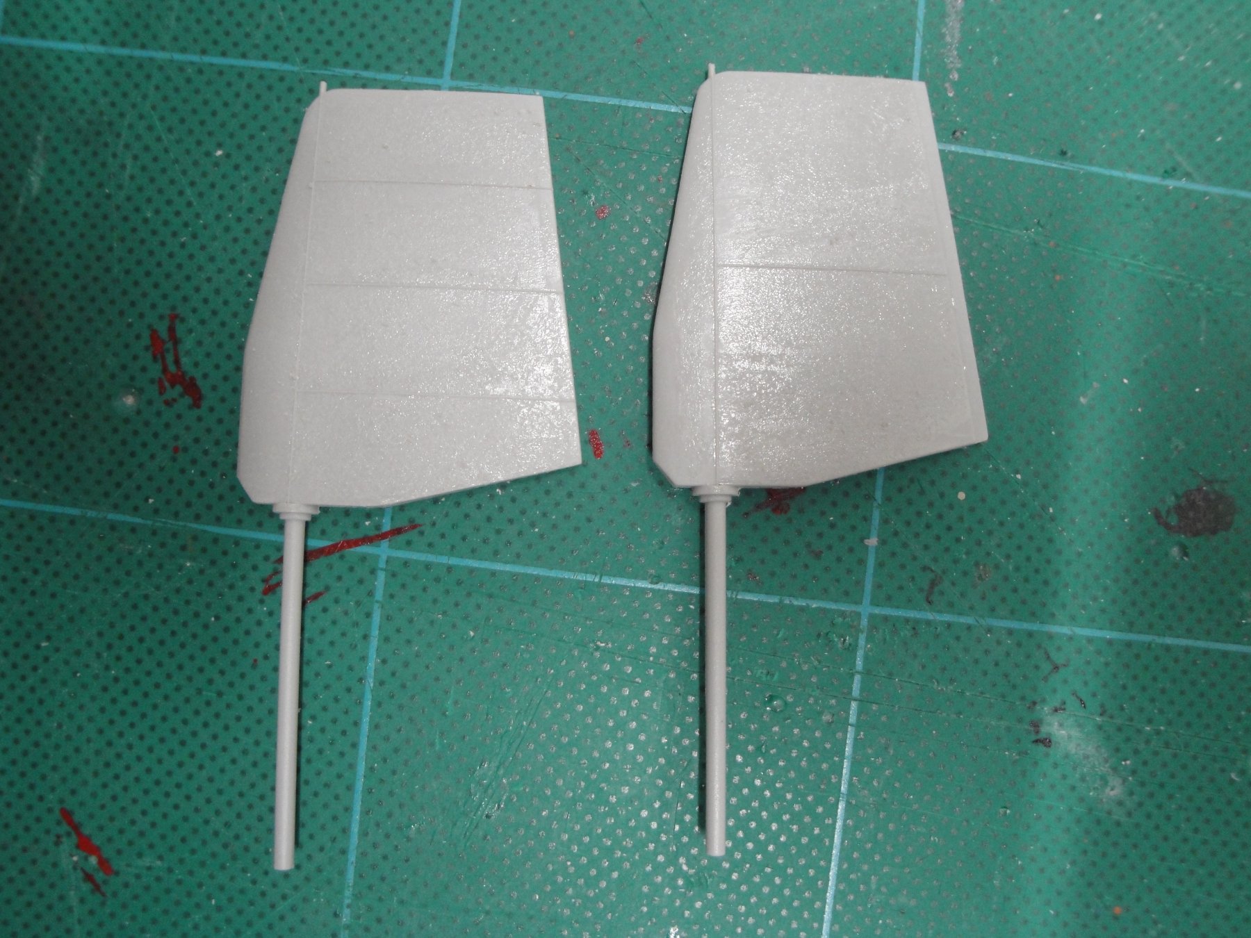
A few more technical information related to the stern of the vessel. First, the rudders mechanism, well rendered by Trumpeter: Then the Rear Diving planes. This one is non existent with the Trumpeter kit, unfortunately. Finally, the rear torpedo door geometry, which is missing completely on the Trumpeter kit but corrected with the RCSUBs torpedo doors addition: Yves
- 760 replies
-
- 12
-
-
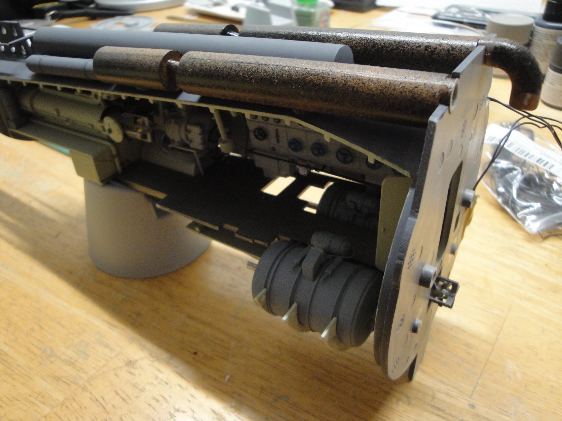
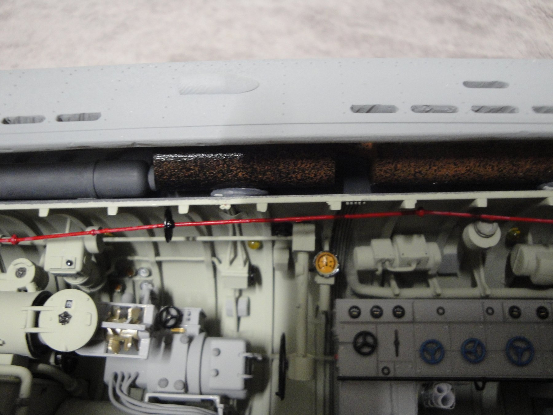
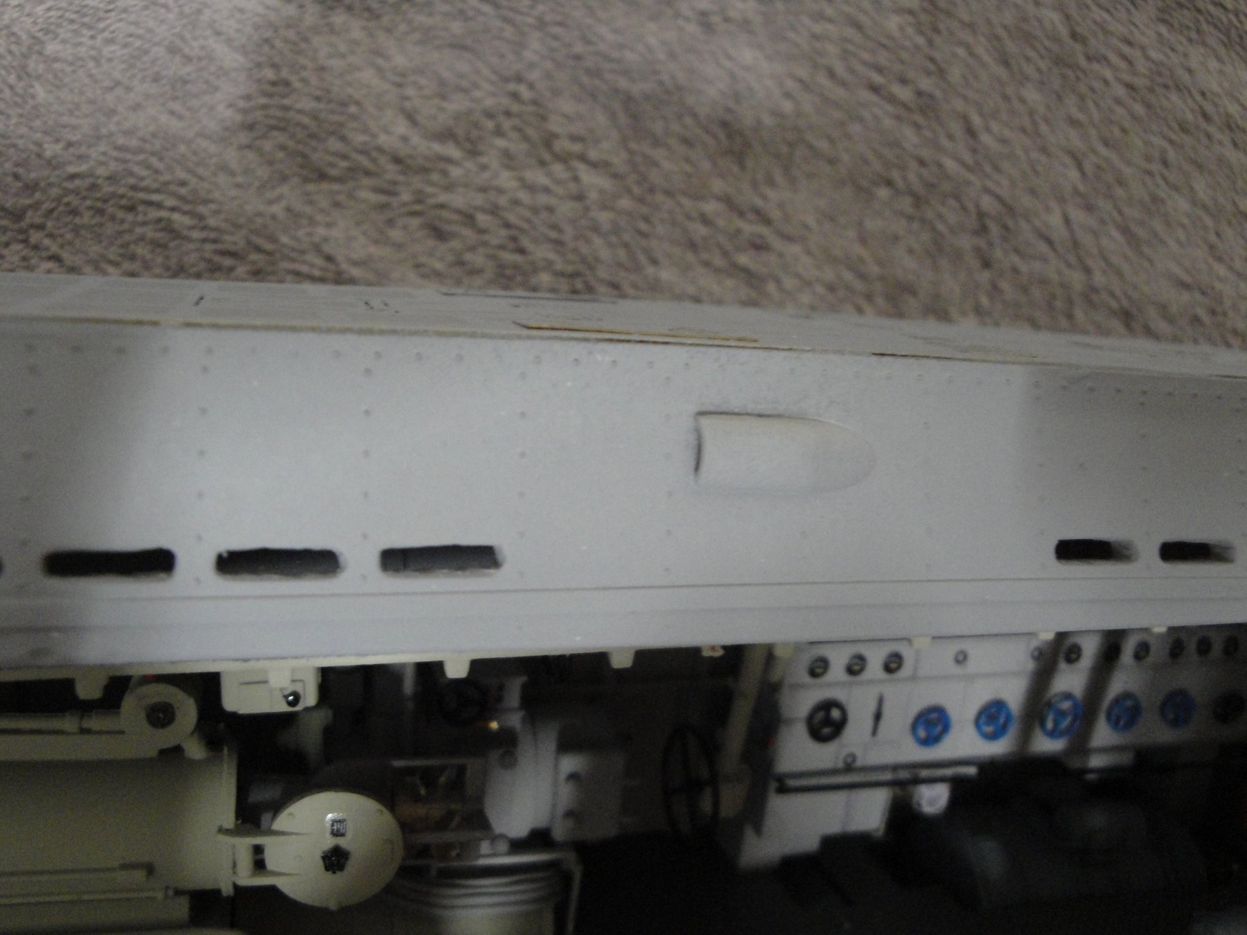
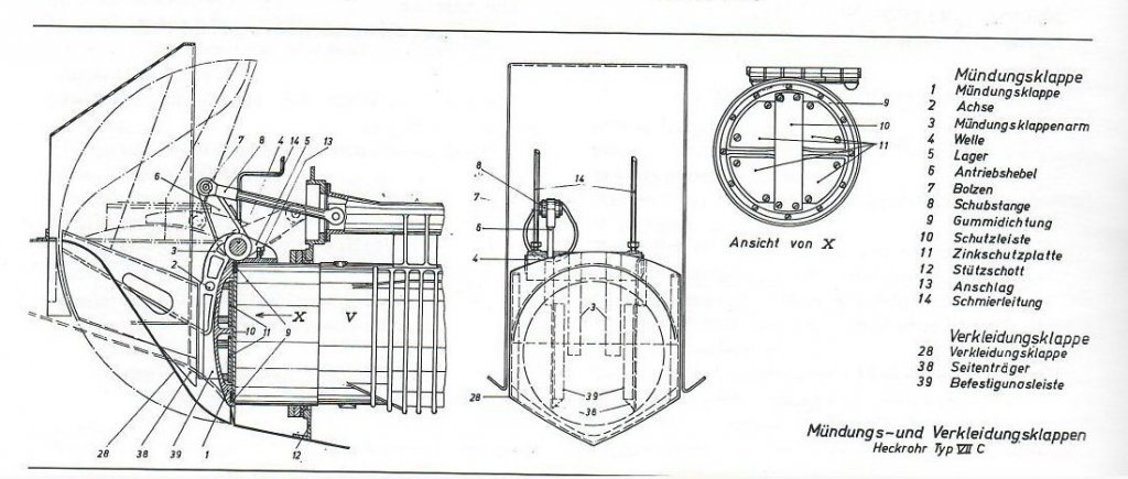
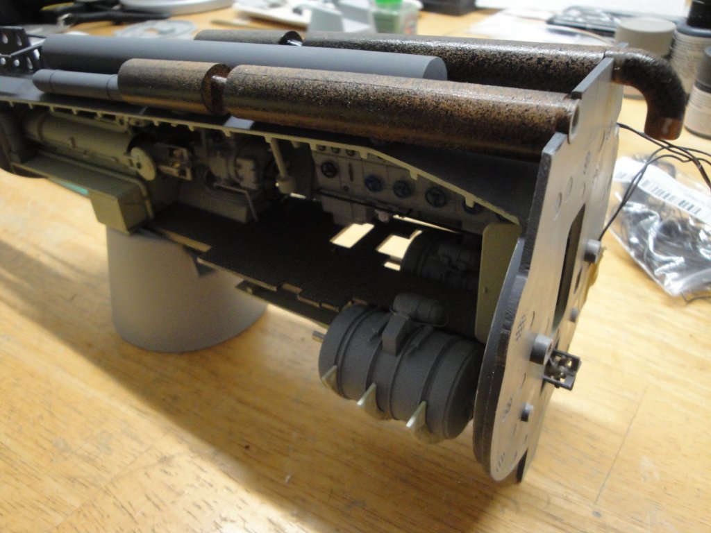
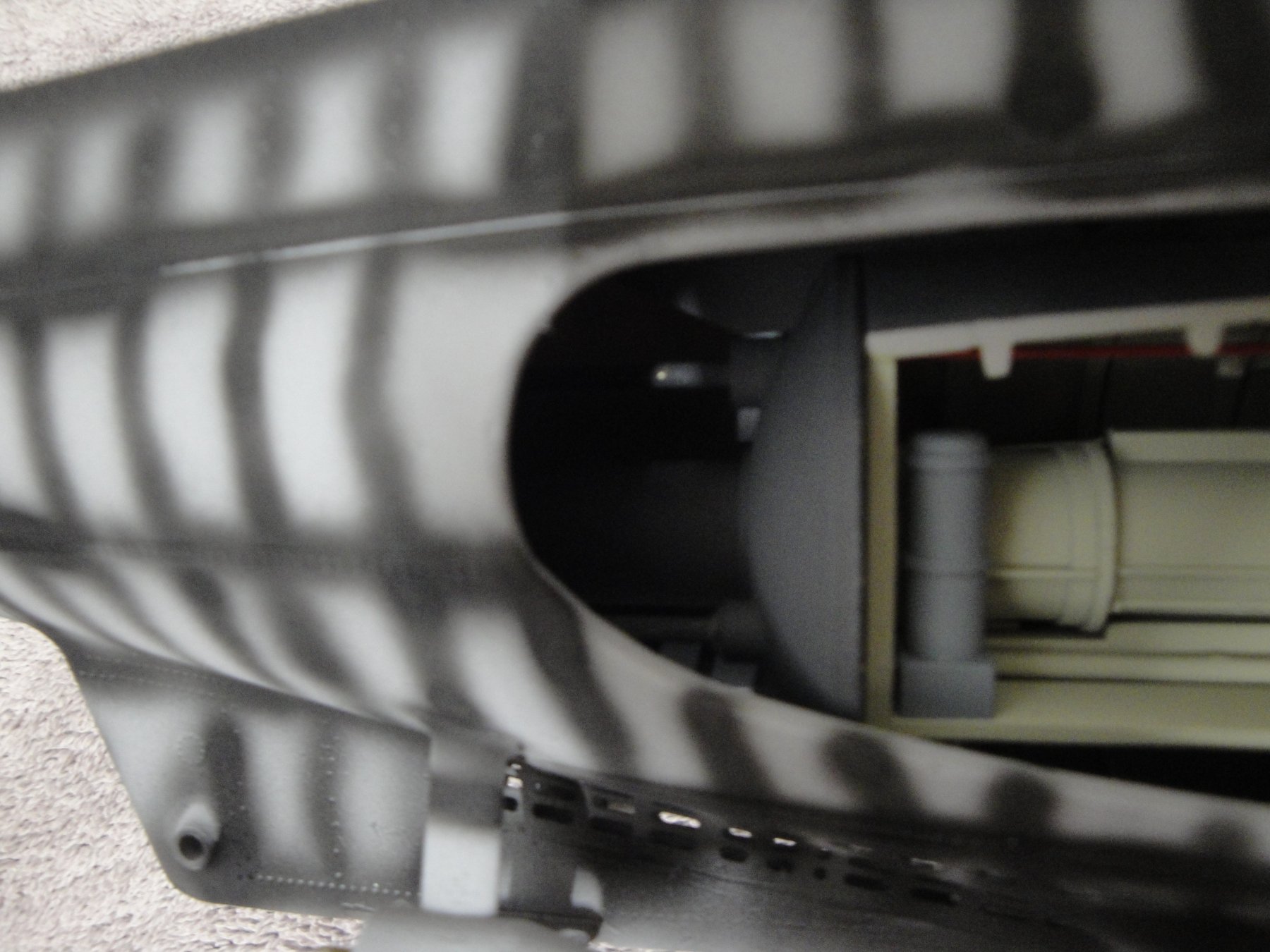
A few pictures and information. The finished pressure roof for the rear torpedoes compartment. My attempts at replicating a rusty exhaust system pale in comparison to what some experts are doing (i.e. RGL). Basically, this is an exhaust painted fully with rust color and then loosely sprayed from a far distance with a black spray can. Not perfect, but it will do.... The (almost finished) module. You can see the work on the main bulkhead to allow the passage of the starboard exhaust. Inserted in the hull: Yes, what you see on the outside of the hull, is actually the exhaust for the diesel engine, after going through the muffler: Another view: The rear torpedo door (still needs some adjustments): The trumpeter kit proposes some kinds of plates to hide "the absence of details" on the pressure hull. My approach is to try to replicate as much as possible of whatever may be visible and offer it for the discerning enthusiast: Finally, the rudders: The barnacle/pitted effect is simply done by spreading Tamiya glue on the surface and taping it with a hard tooth brush. It creates a large quantity of small impacts that simulate to a certain extent, the barnacles, foundry defects and overall wear of the machine. At this stage, you may think that this module is finished. Not really. I still need to work on the transmission clutches and the shaft locks, that Trumpeter skipped (again) as they did for a lot of details. Yves


- 760 replies
-
- 23
-
-
Since we are talking about storage, I am trying add a few details to the outside of the pressure hull. As you can see from the drawing below, the top of the pressure hull has that large torpedo storage container, two pressure tanks for the ballasts and the two exhaust systems for the diesel engines: I am trying to place all this equipment on the existing compartment, by reworking the bulkheads and using some spare parts from the second set of parts. All this, while keeping in mind that this compartment may be installed permanently in the hull. I am still debating. The hatch for loading the torpedoes inside the rear compartment has been totally skipped by "the Trumpeter". I could do it, since I have a spare hatch (you can see that on the right of the drawing "achieres Torpedo"), but it would involve too much butchery of the existing compartment and would conflict with existing parts. Besides, it will not be visible at all. Compromises....as always. Yves
-
Same torpedoes front and back. Only three direct shots from the stern (2 under the flooring, and one in the tube. Plus an additional one in the storage outside of the pressure hull. You had to surface to get to it. Not an easy job. Yves
-
I would go with B. Plus spread generously fish oil and other repulsing fish guts on top of it. Yves
- 337 replies
-
- 4
-
-
- finished
- mountfleet models
- (and 1 more)
-
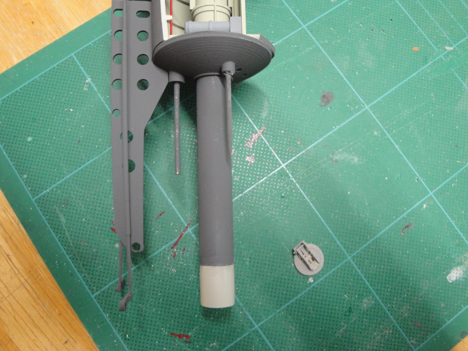
While fitting the compartment into the hull, I realized that Trumpeter made a mistake: the length of the rear torpedo tube is too short ! They molded all the parts (front and rear) in the same way, and the rear is too short of 1.4 cm. Thus, using the spare parts I have, I extended the tube accordingly. I tell you, they are consuming way too much rice alcohol, over there.... Yves

- 760 replies
-
- 16
-
-
Why not use the clay bar used for automotive detailing. You will have to use it wet, though.... Yves
-
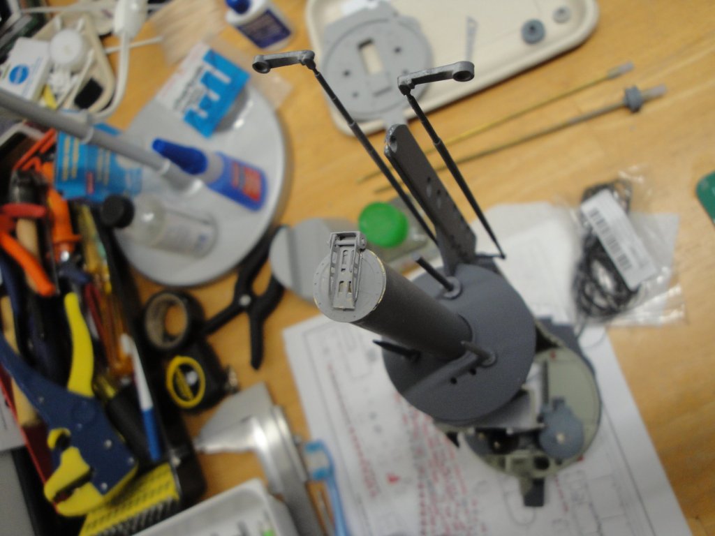
A couple more details: The paper/plans holder is one of the rare Trumpeter parts made of photo-etched brass. It is of excellent quality and very well designed. It si truly regrettable that Trumpeter did not provide more internal PE details to improve the level of accuracy of that large model. From RCSUBs, the rear torpedo outer door has been installed. I also added a brass rod (interrupted) for the door command as well as two toothpicks for the diving planes controls. Those will only be visible for an inch or so through the opening on the starboard hull and thus, there was no reason to extend them. Besides, their extensions would have prevented the insertion of the module in the hull. Yves
- 760 replies
-
- 17
-
-
I like the planking in the center approach. However, you will not be able to install any guns, with this method. You could also try planking in a less geometric way, and have it only where you need it to support a gun or a specific part of the deck. Yves
-
Beautiful model. And you are moving rather fast.... Yves


.jpg.79d074792b592d6bfe7a908f963e395c.jpg)
.jpg.c4e5824444a6a1e276e9f3e99de42795.jpg)