DONATION DRIVE - SUPPORT MSW - DO YOUR PART TO KEEP THIS GREAT FORUM GOING!
×


yvesvidal
-
Posts
3,617 -
Joined
-
Last visited
Content Type
Profiles
Forums
Gallery
Events
Everything posted by yvesvidal
-
 You did a fantastic job on the gold ornaments. Yves
 -
Please take some pictures from the show (if your hands are not too busy with kits and parts). Yves
-
That is a good feeling. I love it when I am discarding empty sprues or laser cut wooden plates, devoid of any parts. It means two things: 1) You are making great progress and 2) It is time to think about your next project. Yves
-
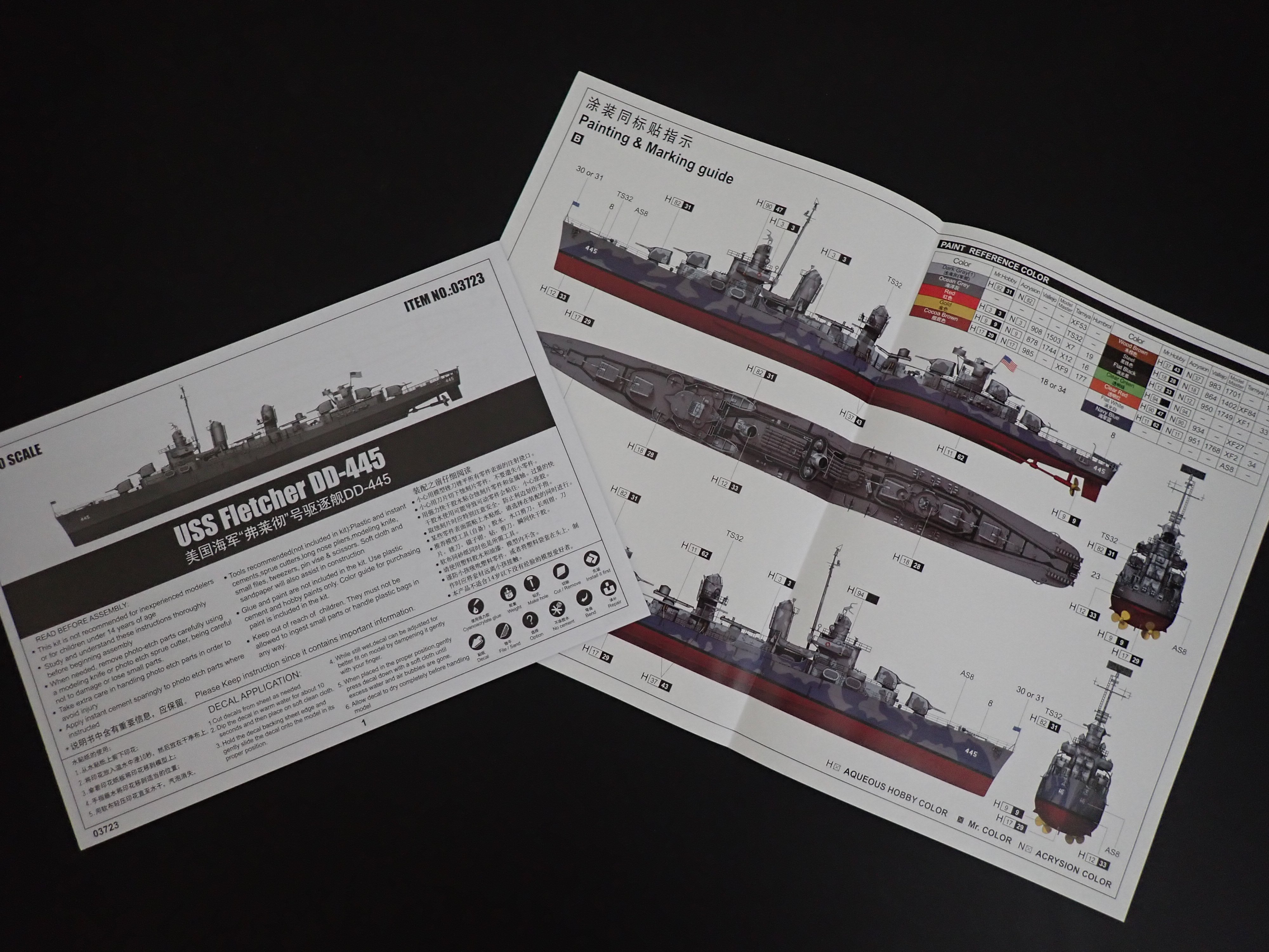
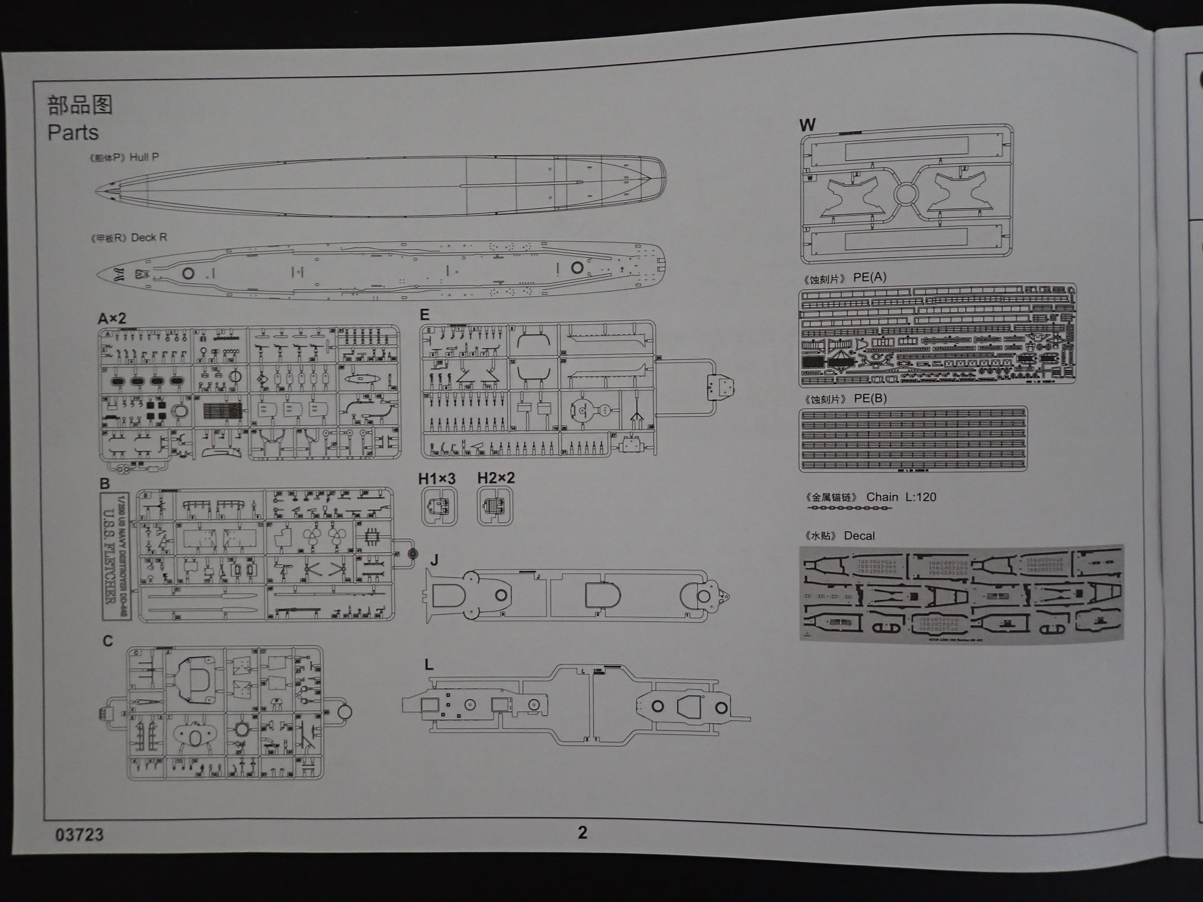
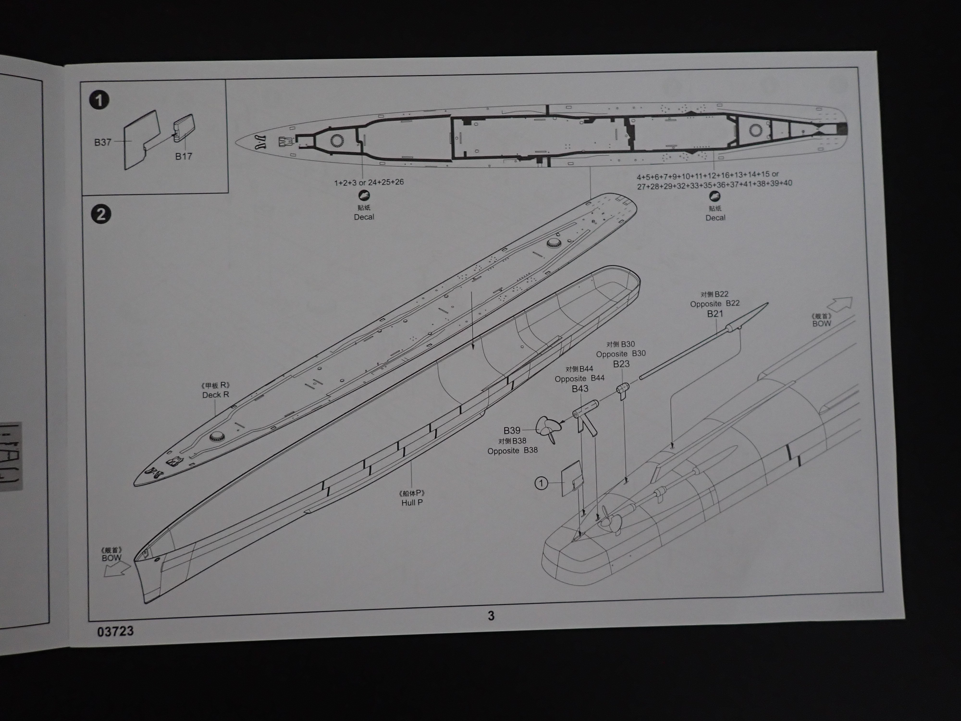
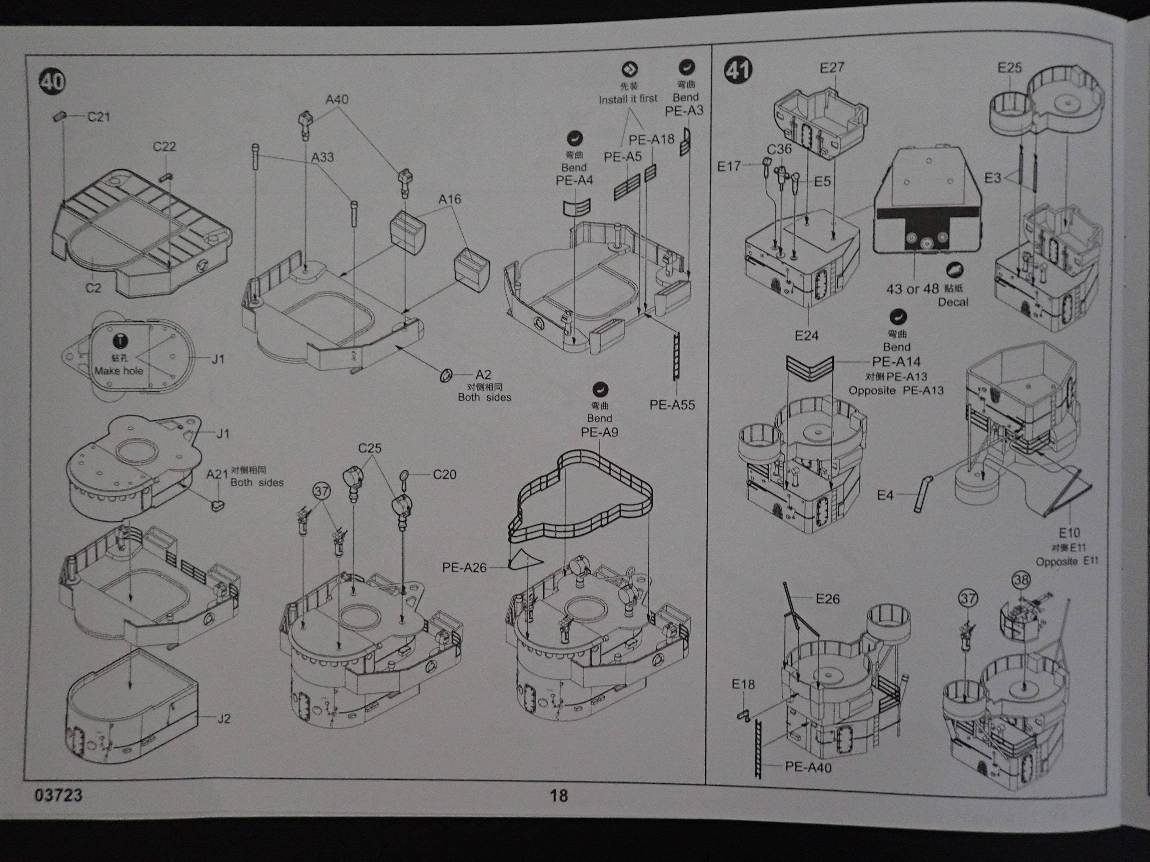
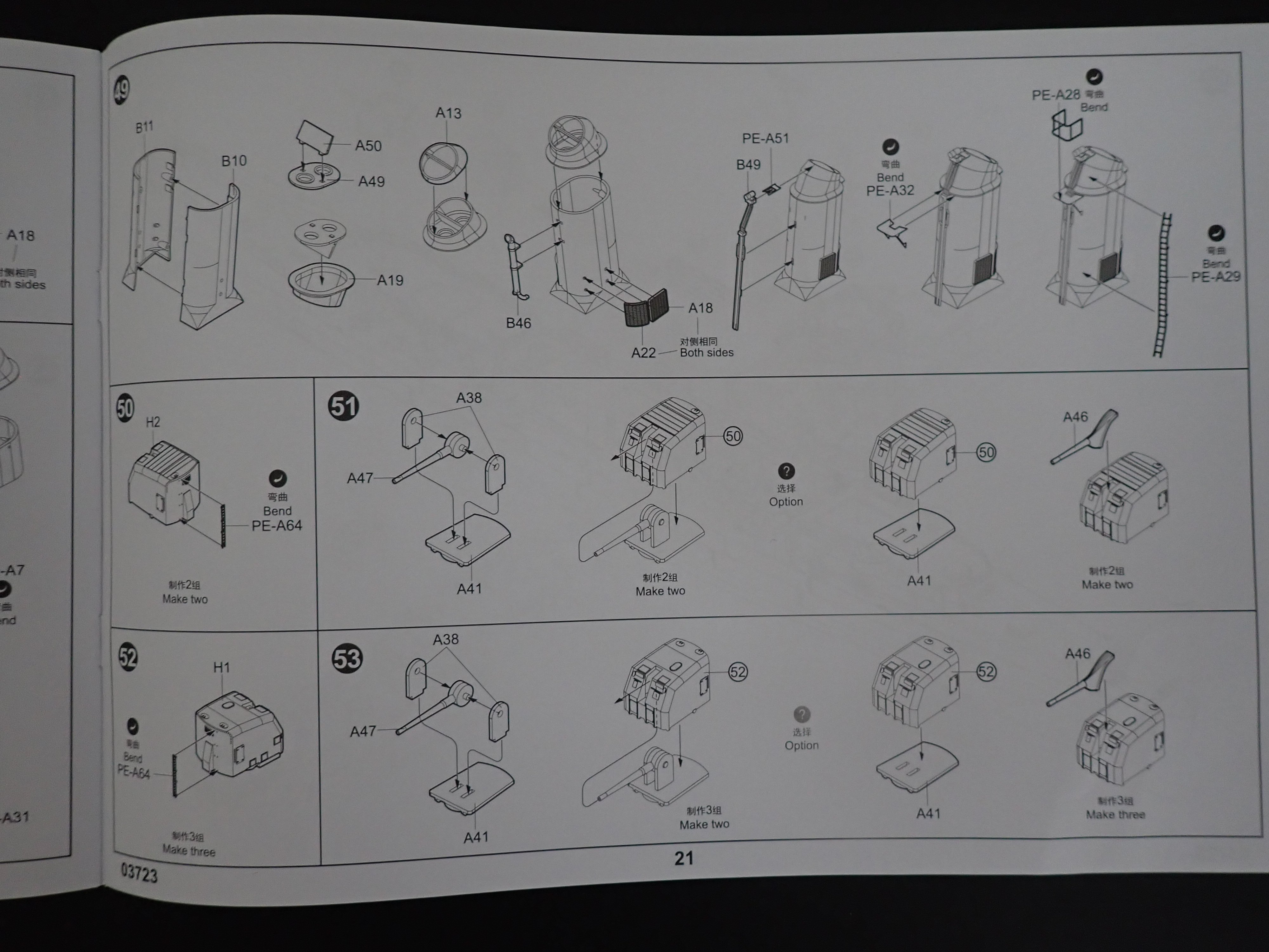
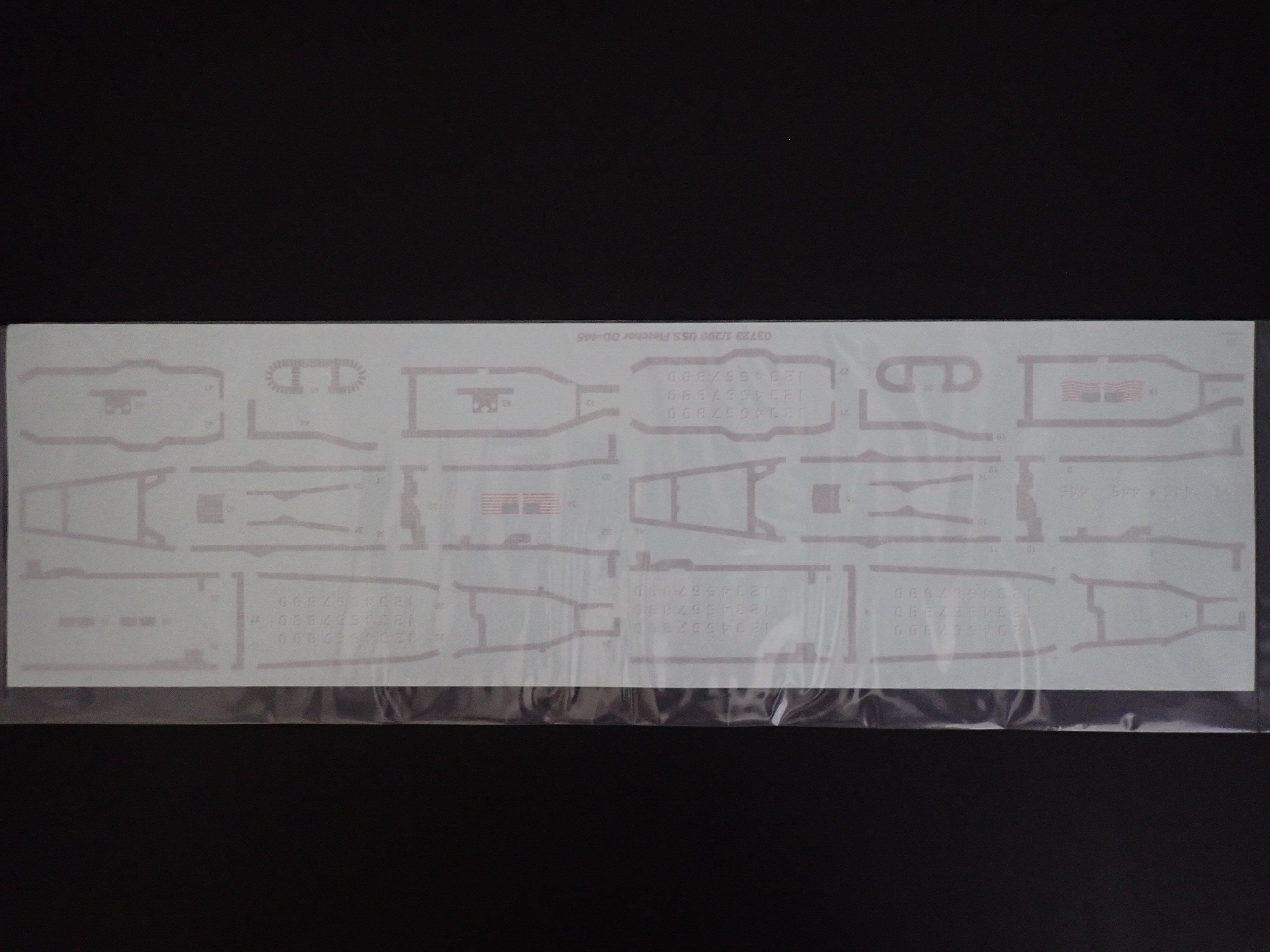
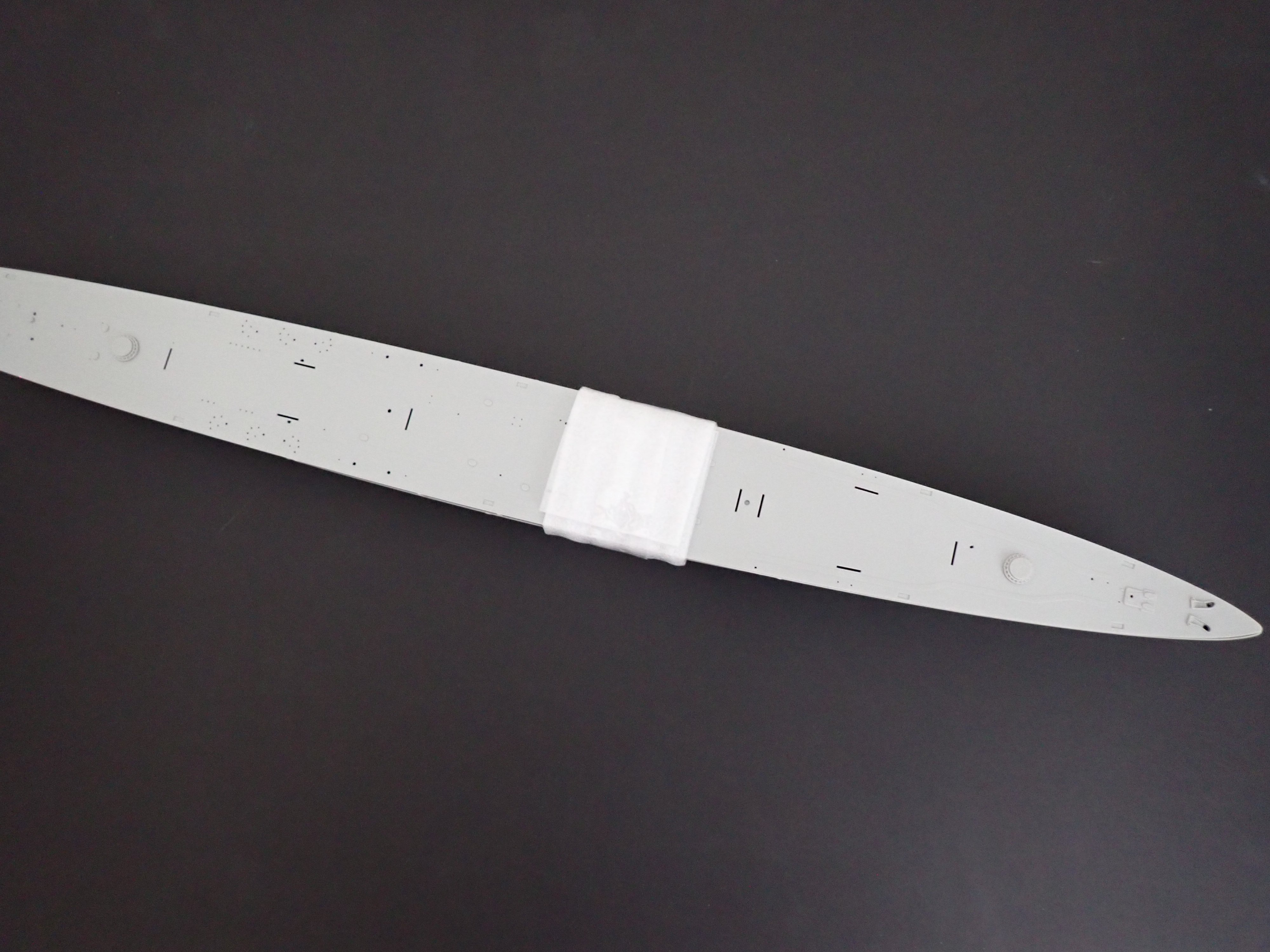
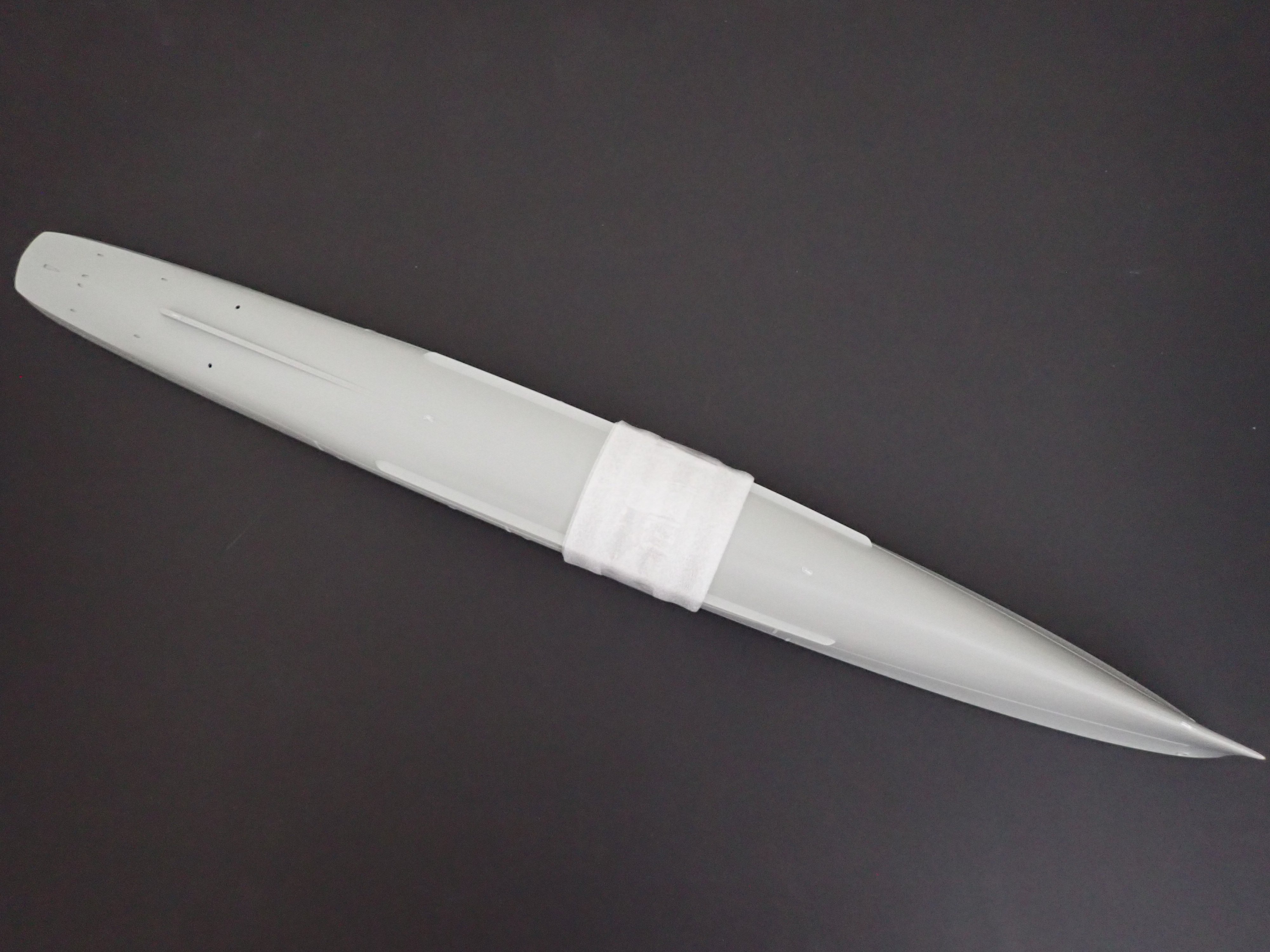
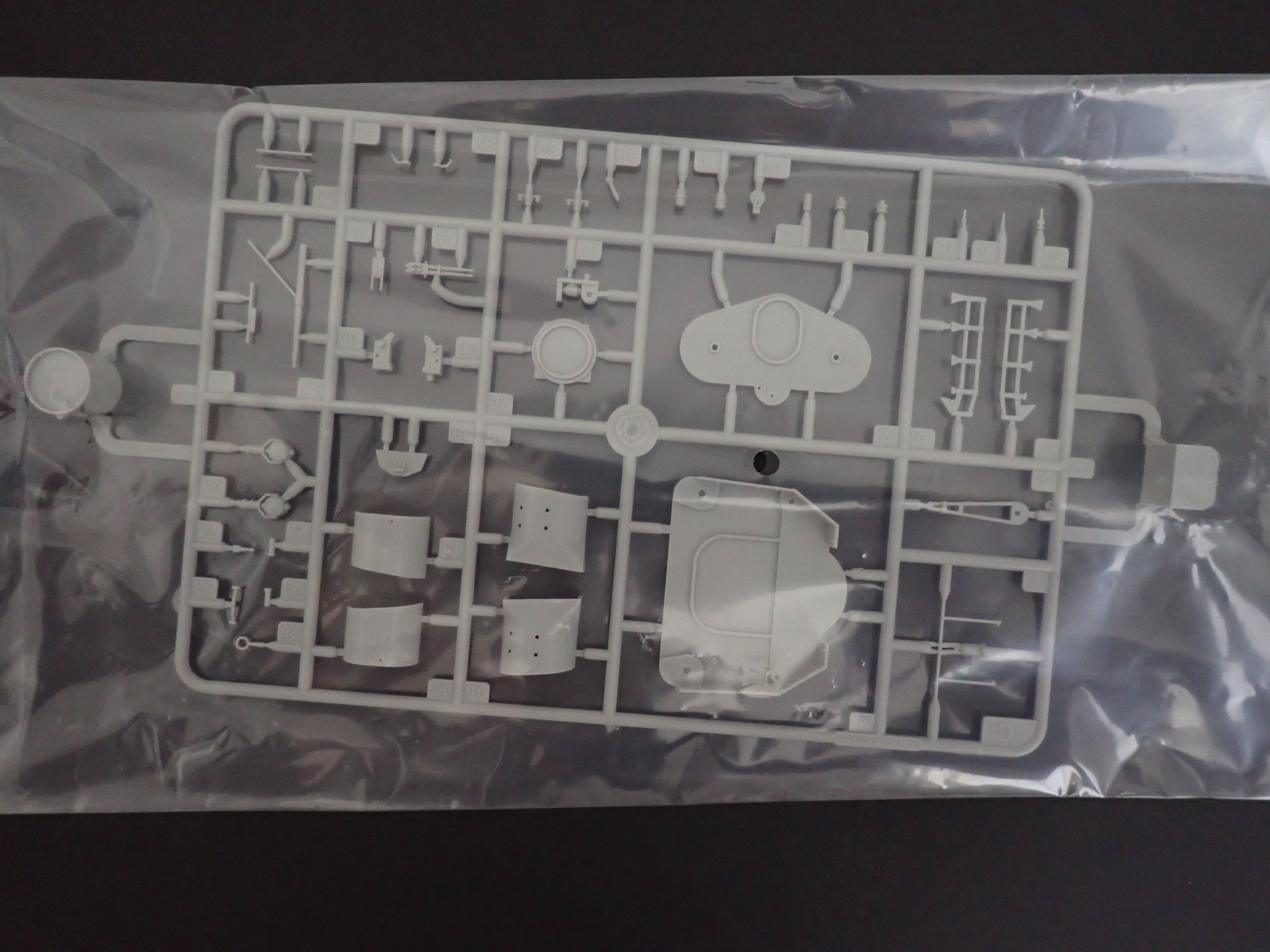
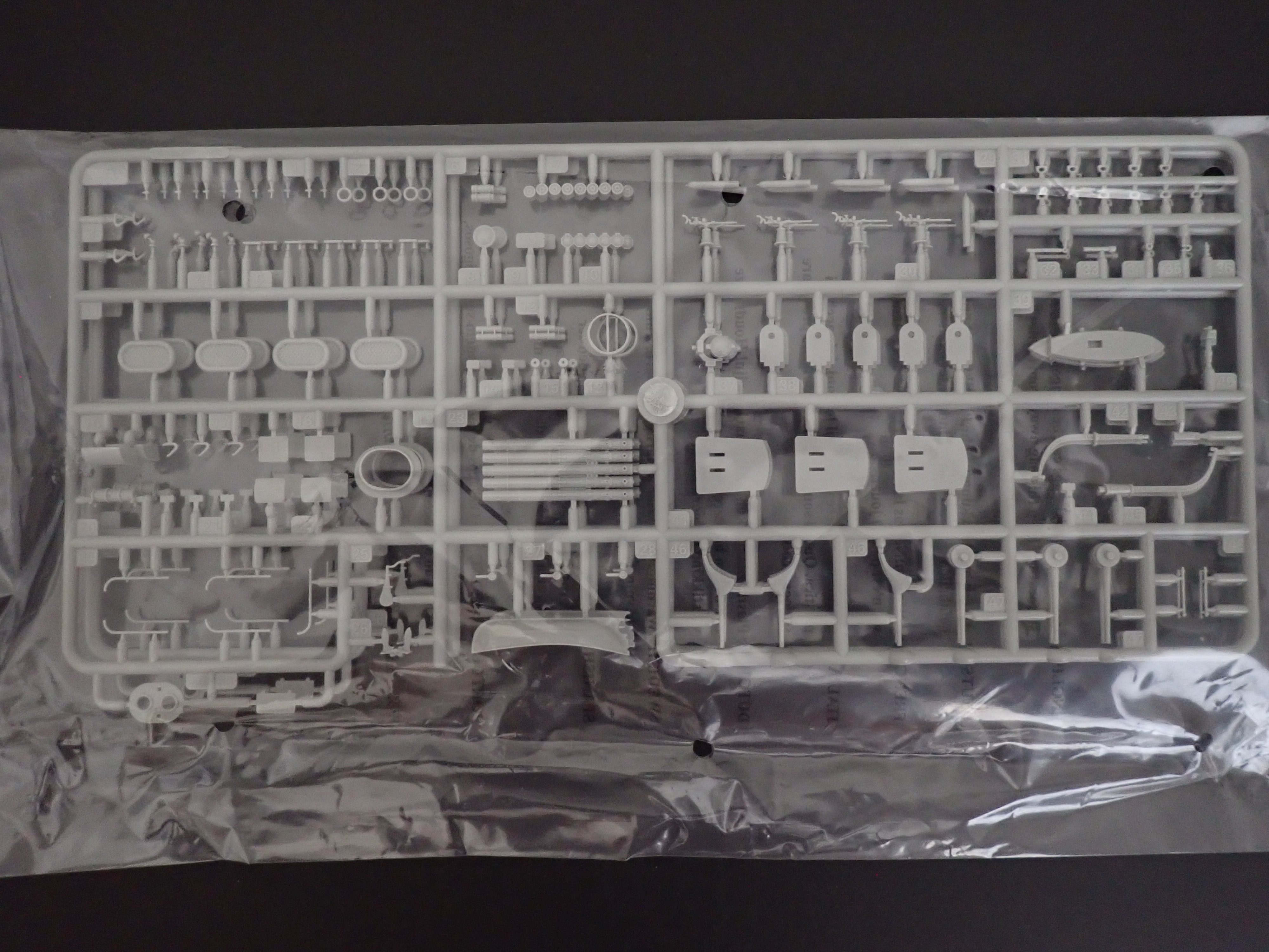
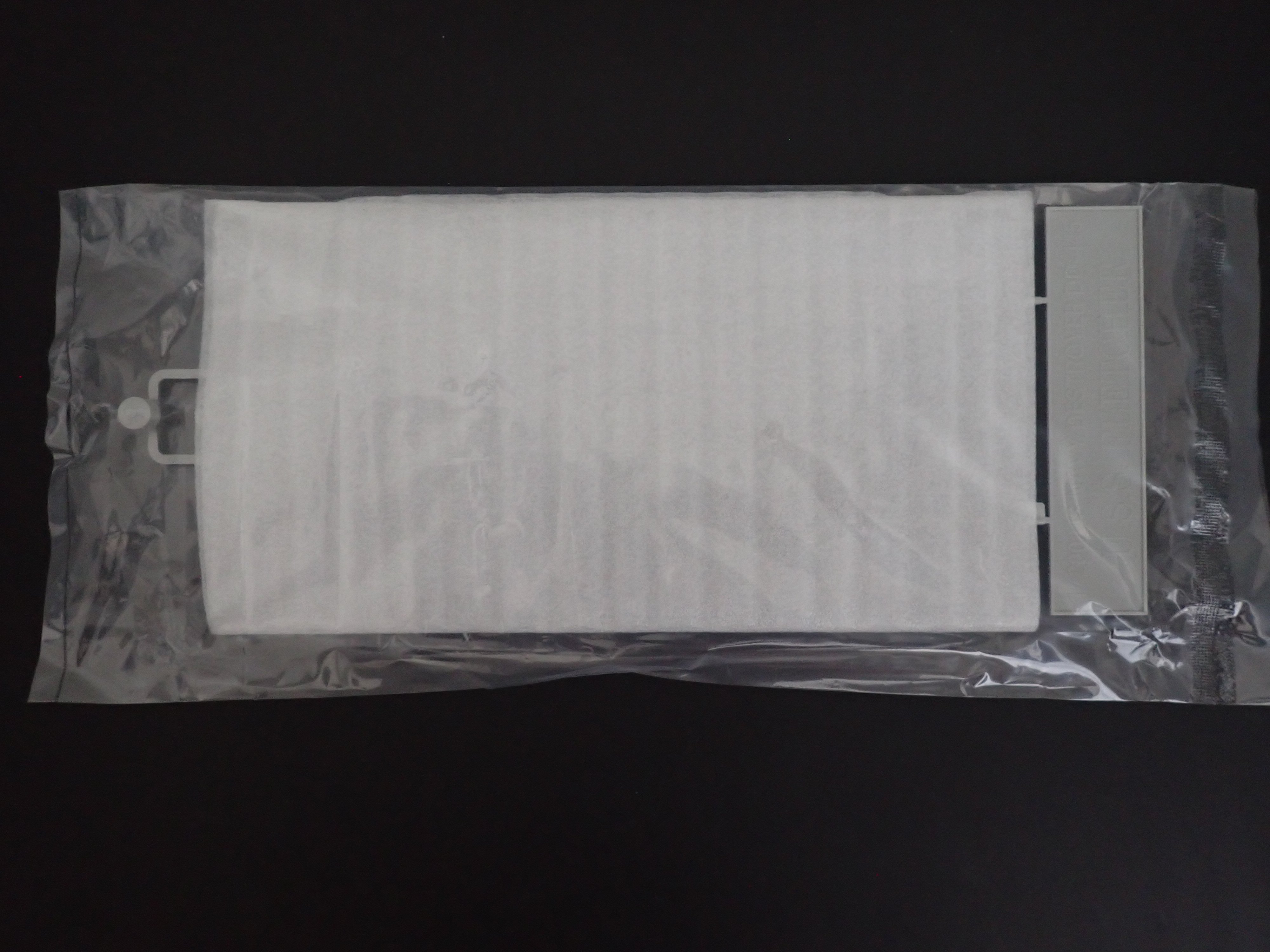
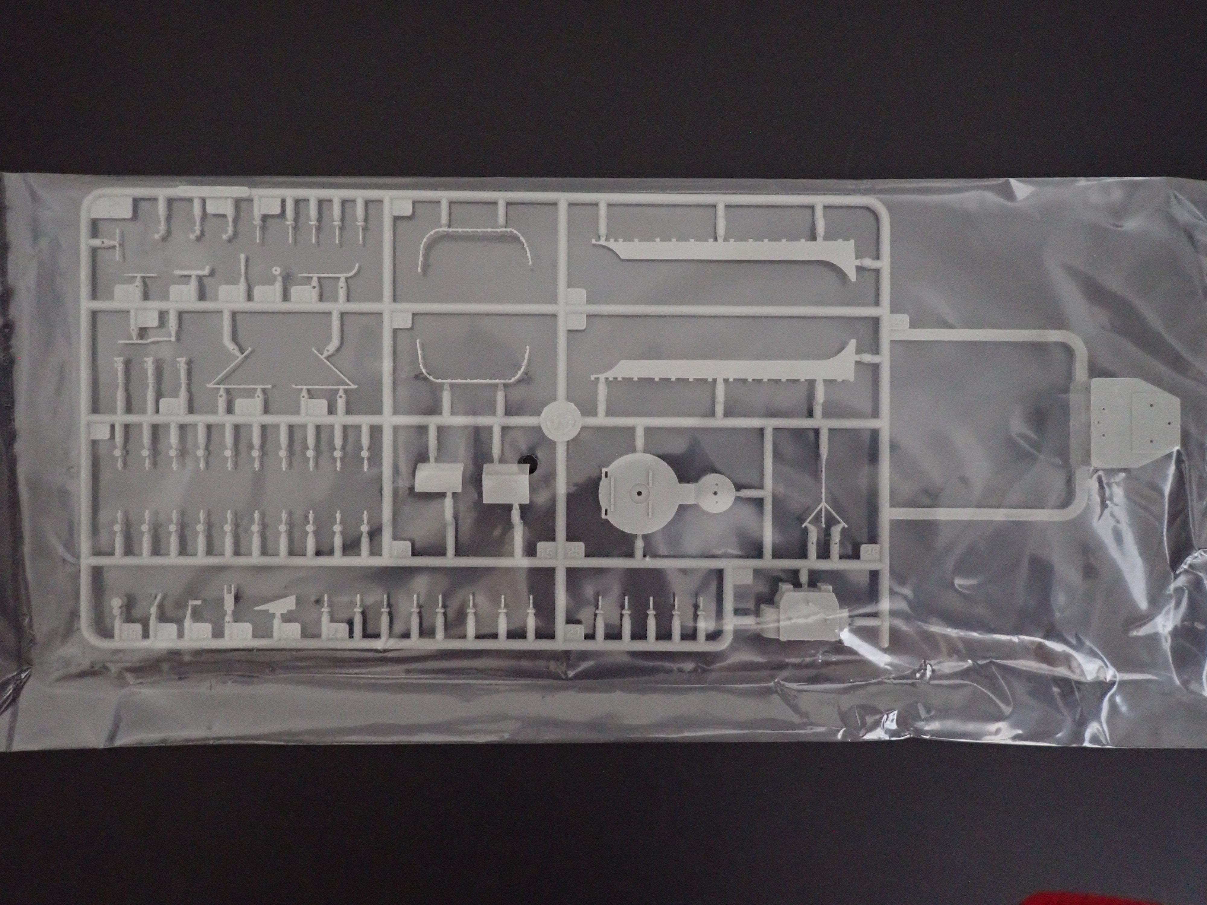
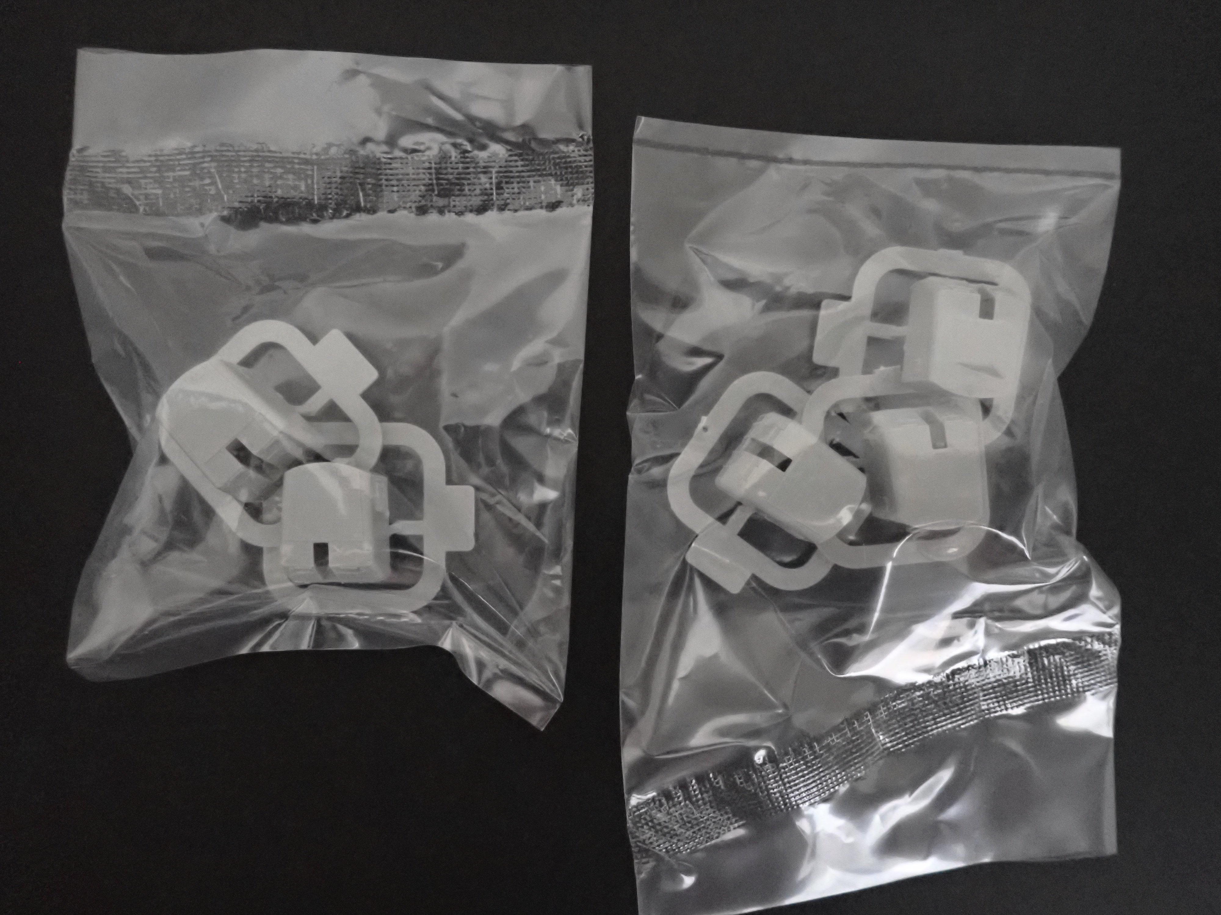
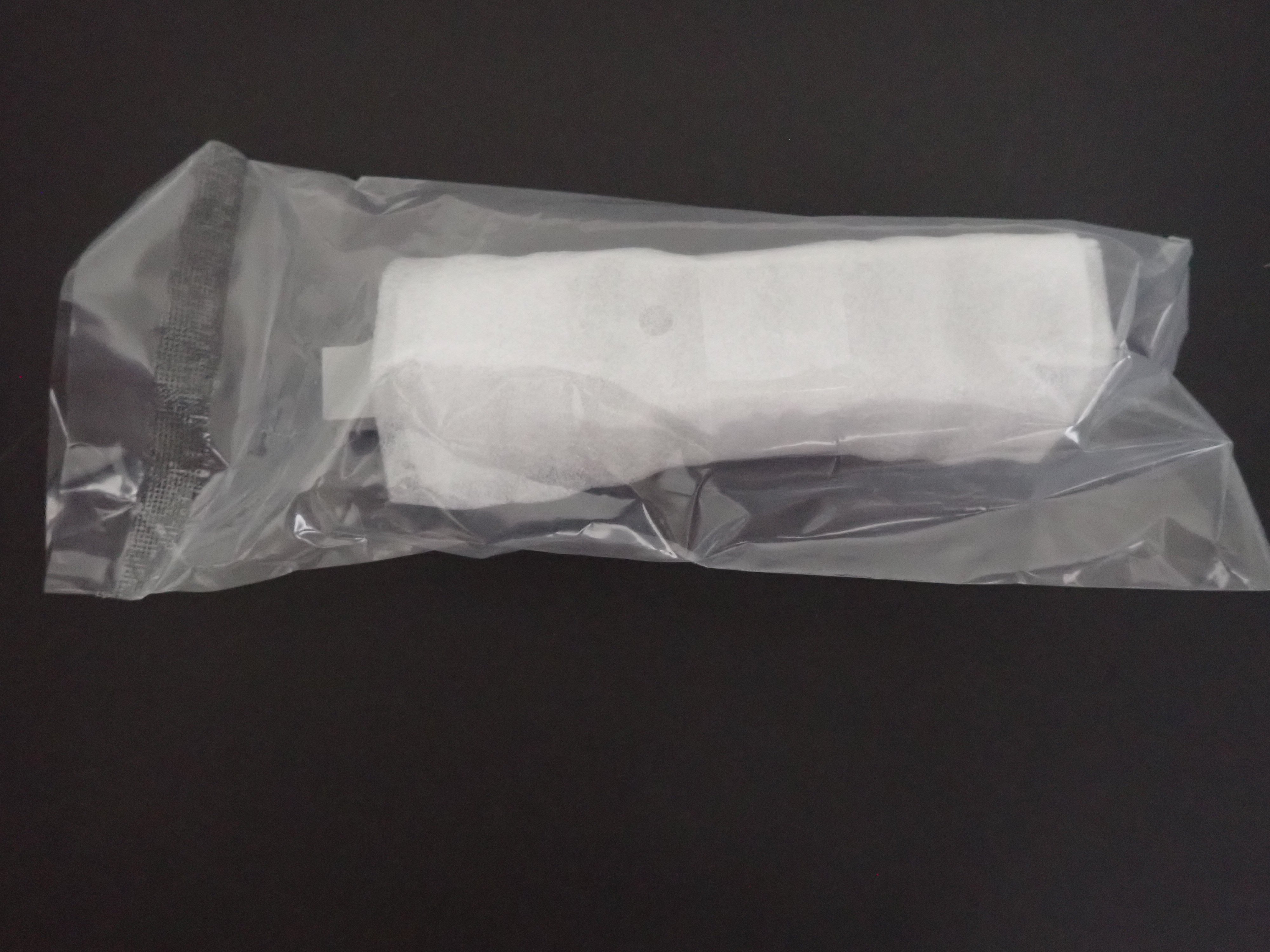
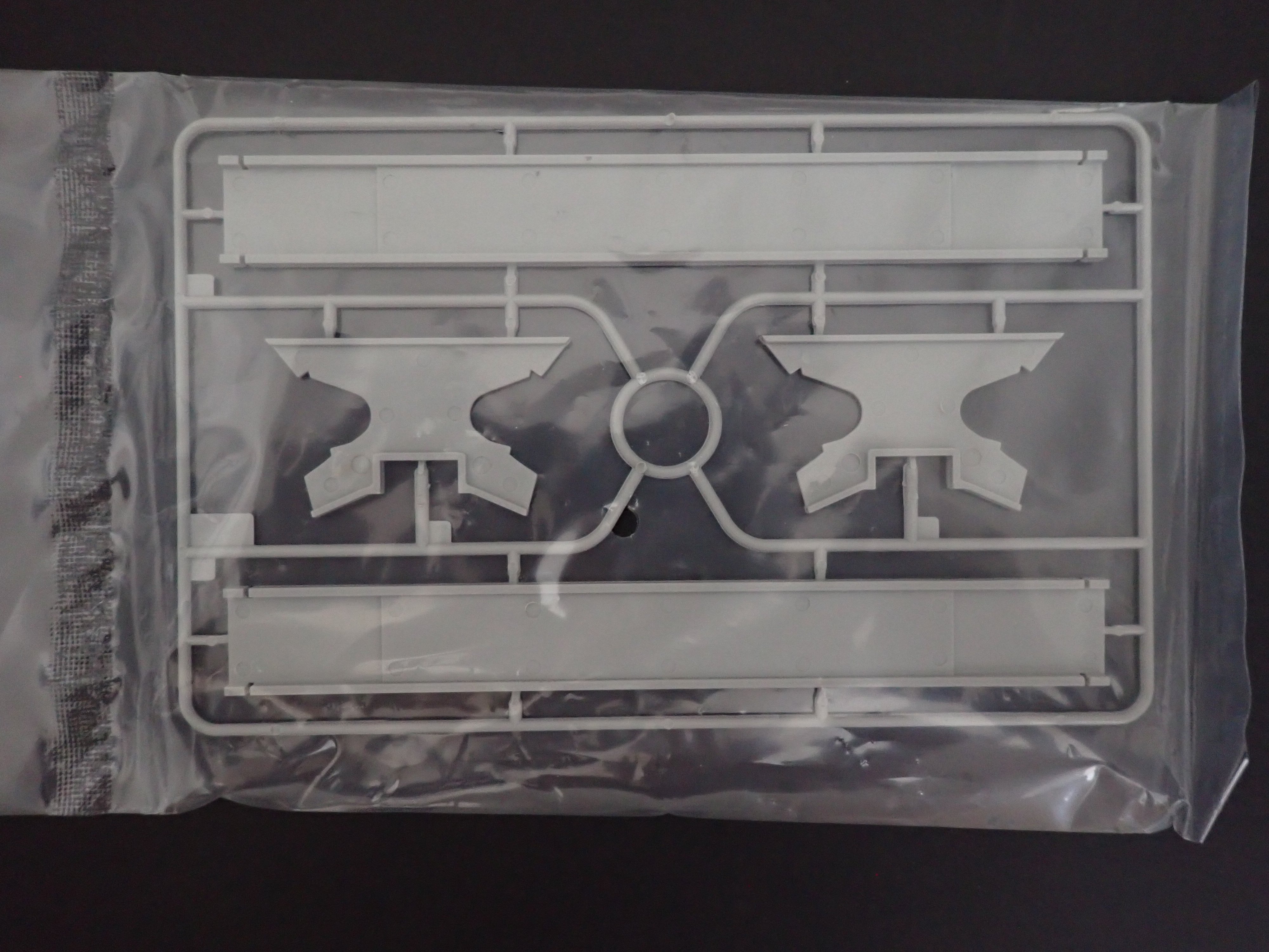
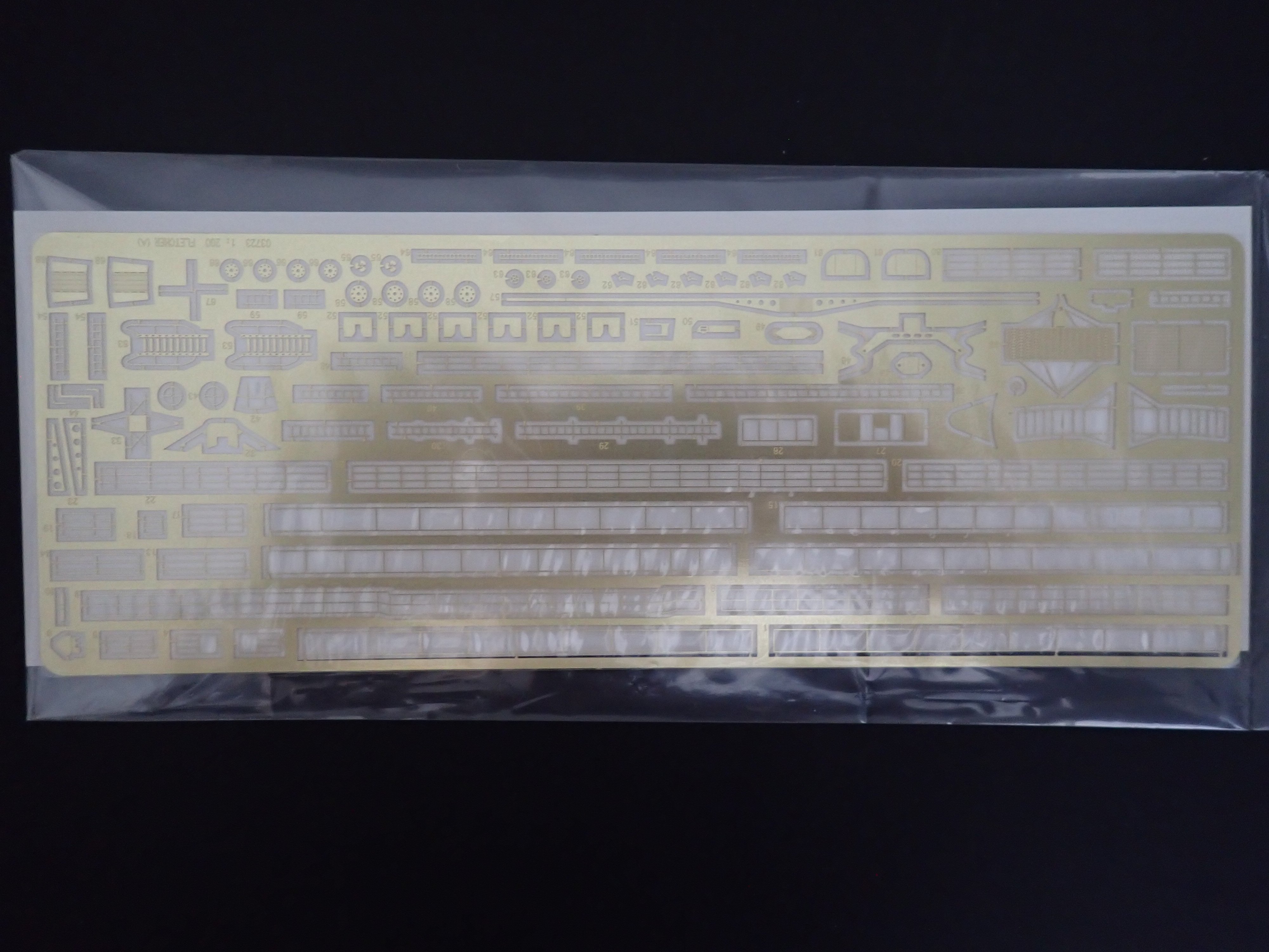
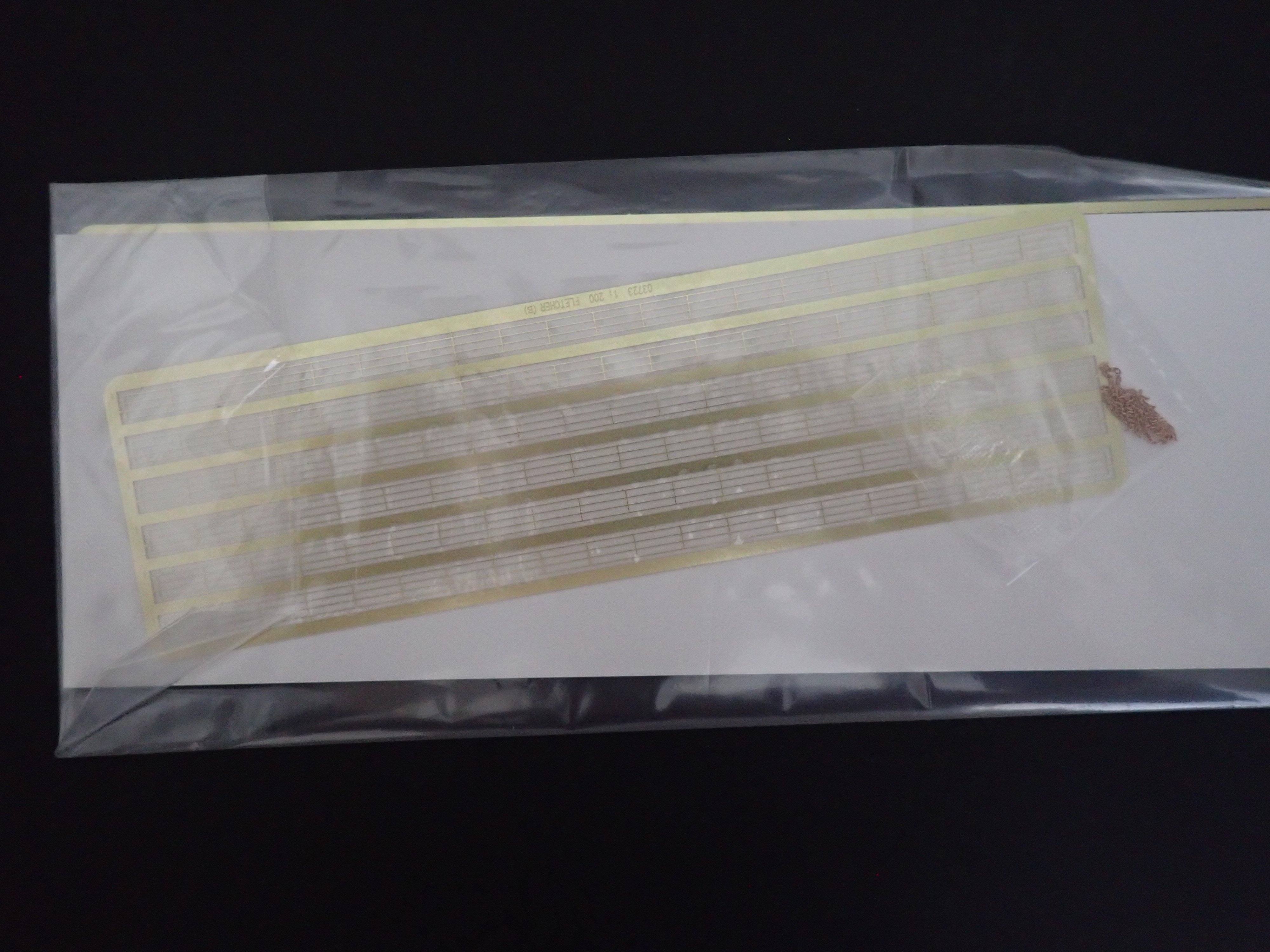
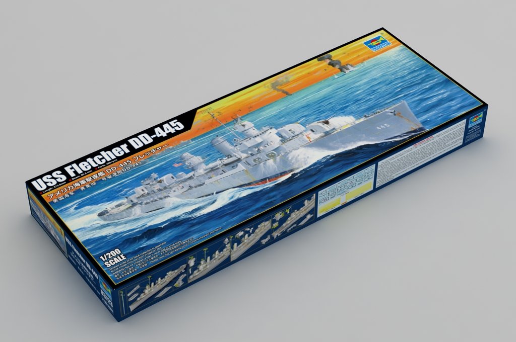
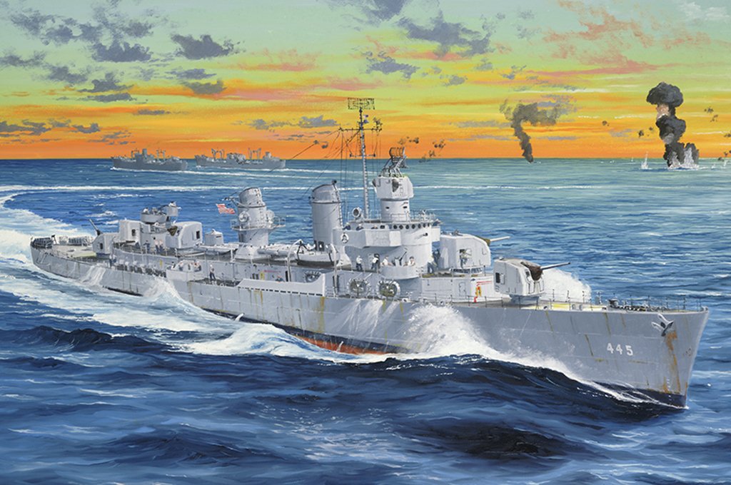
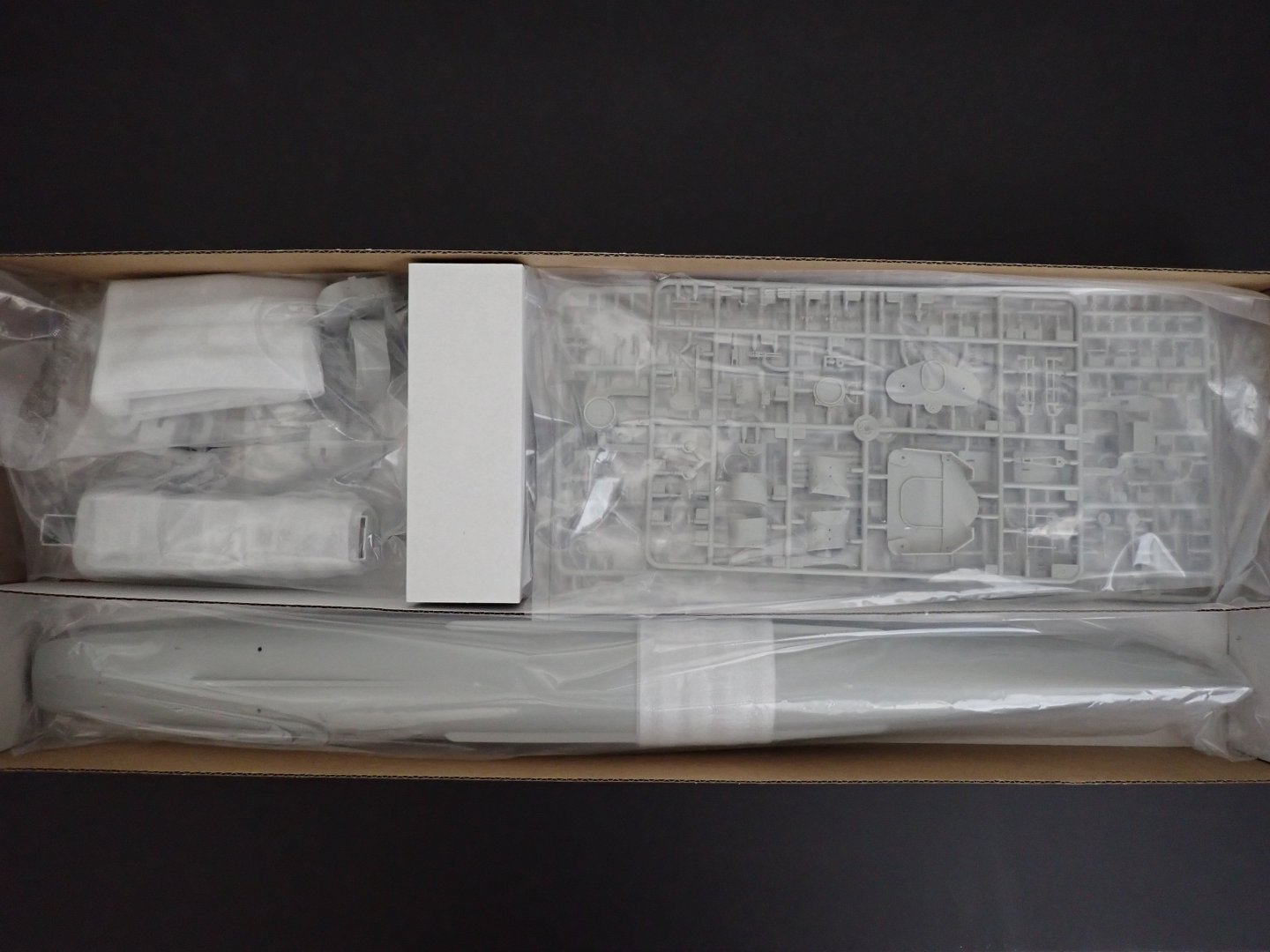
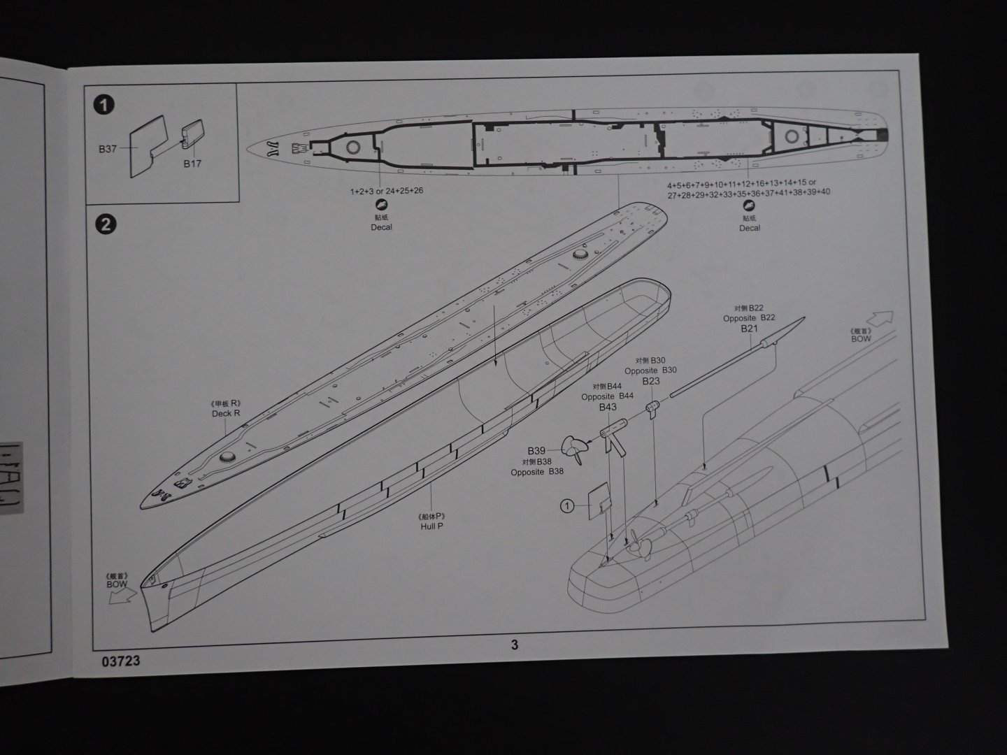
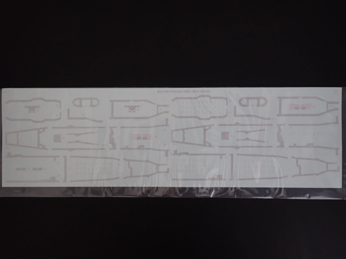
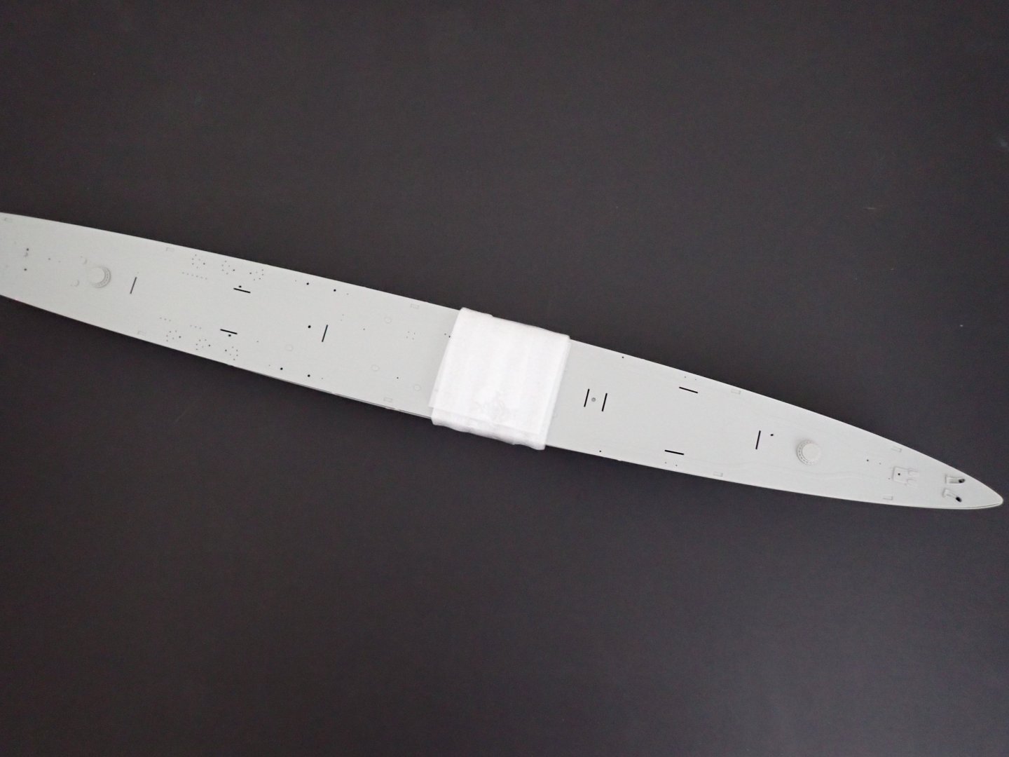
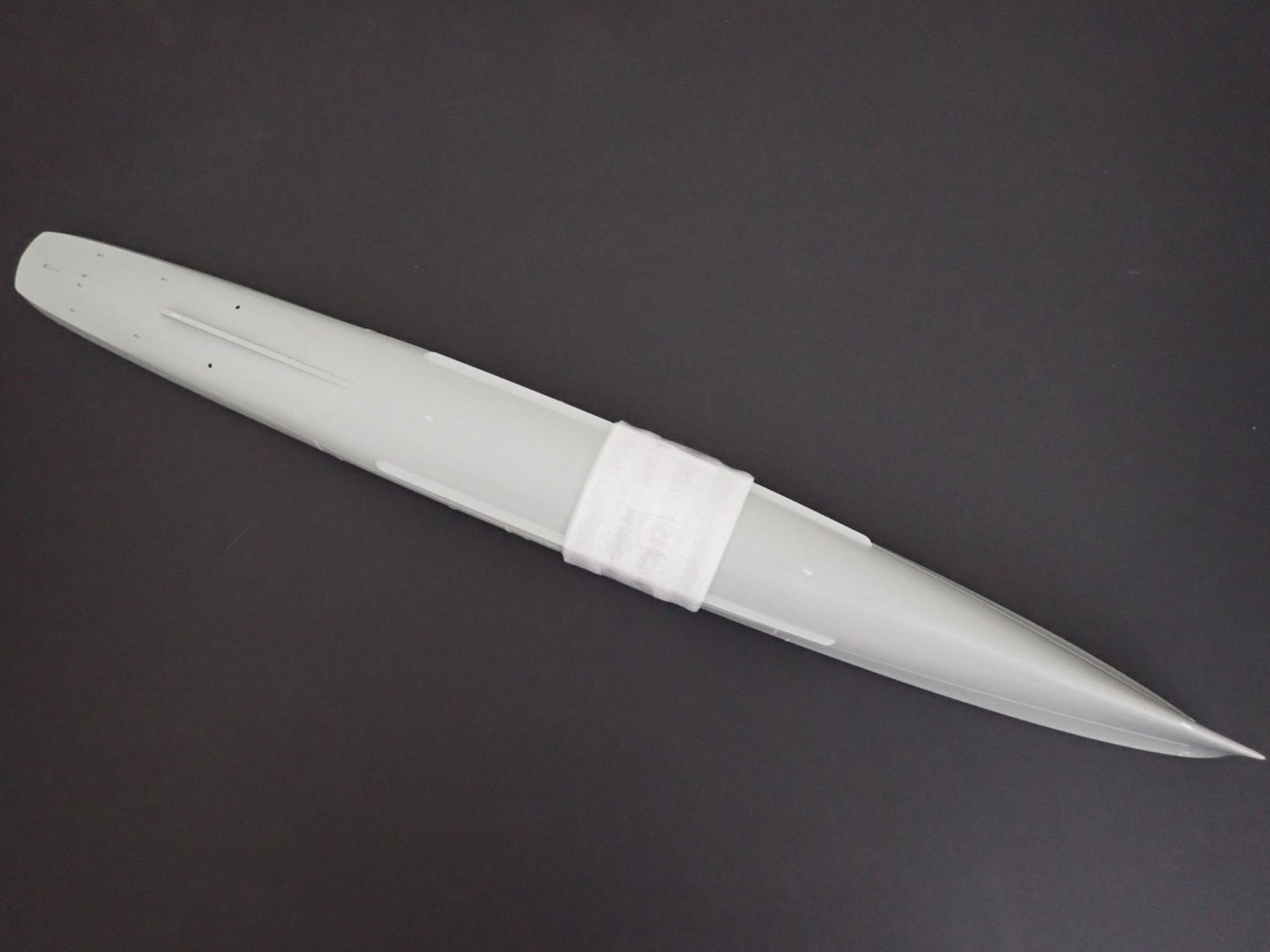
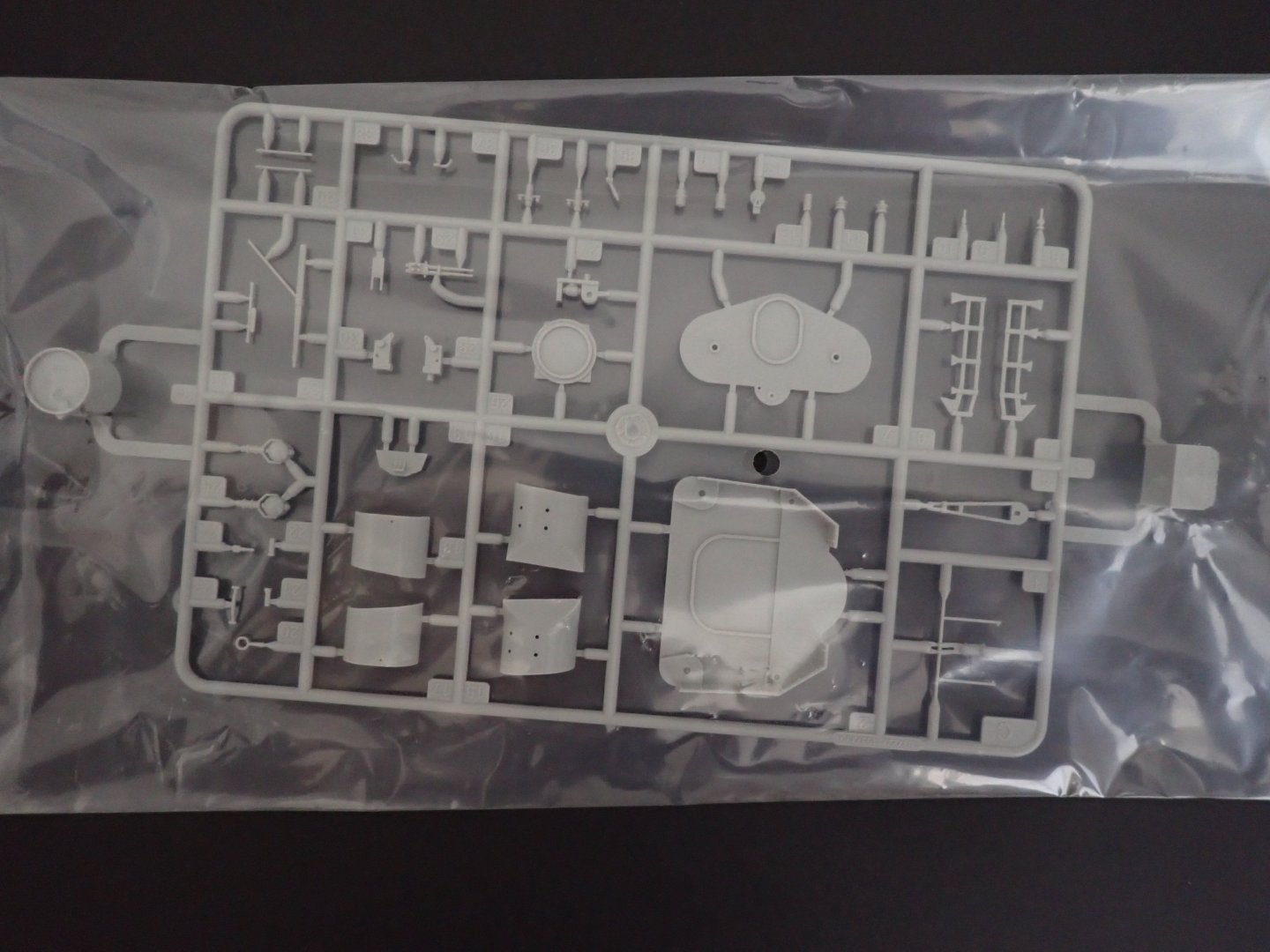
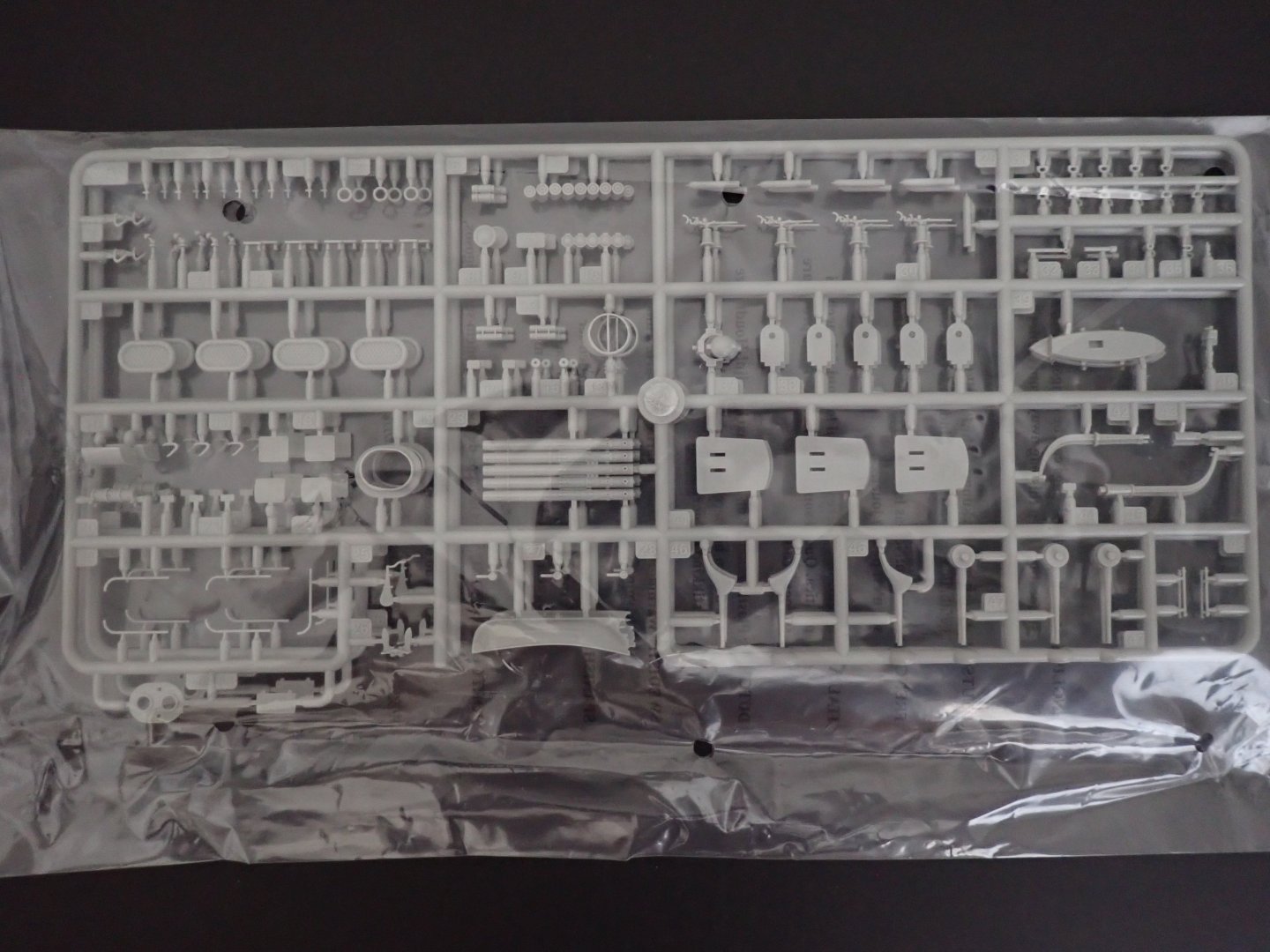
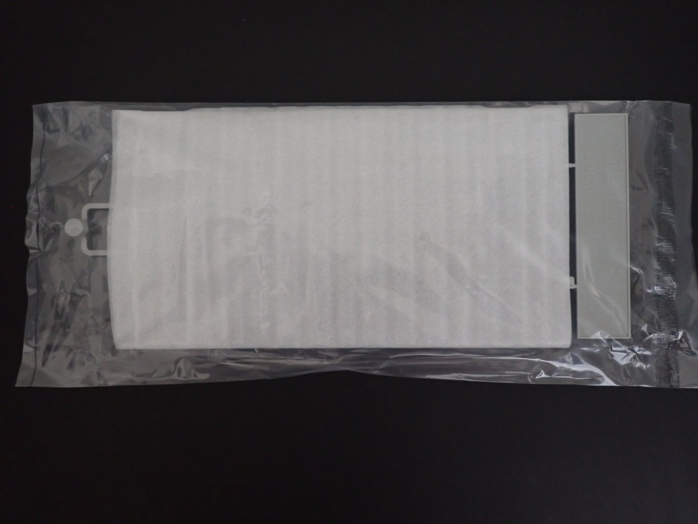
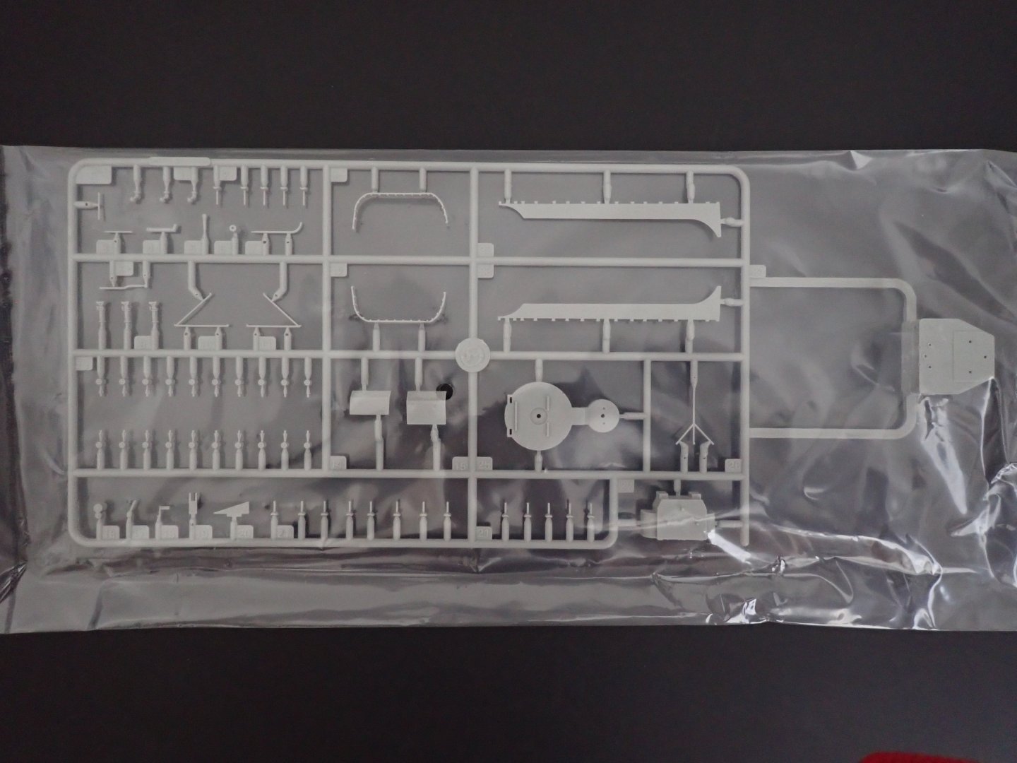
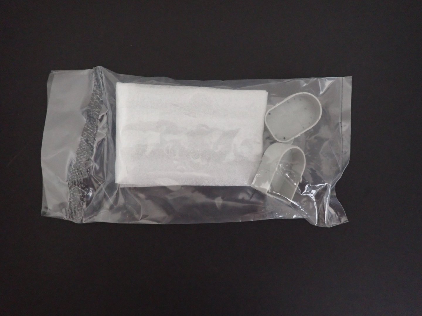
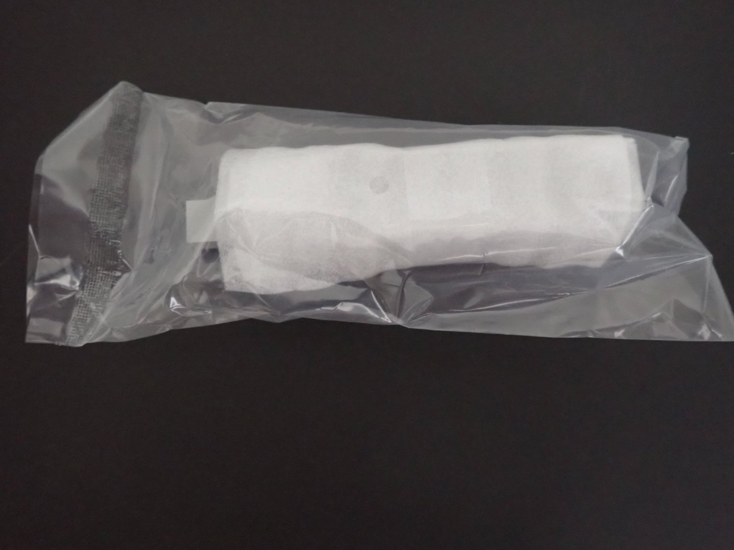
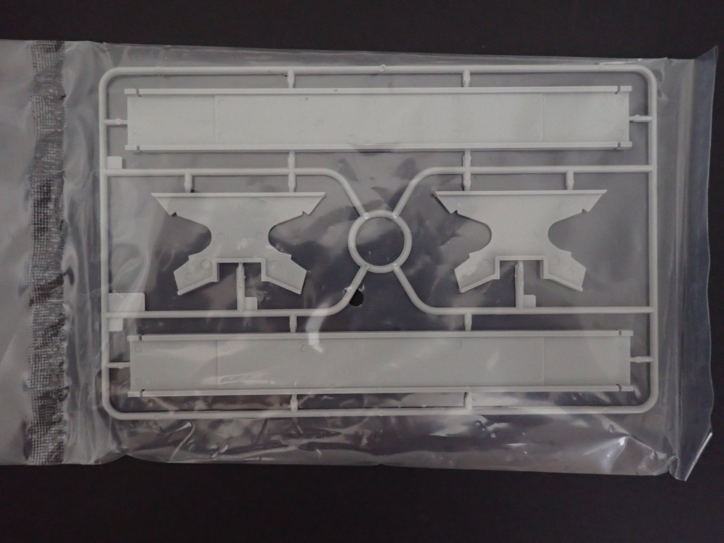
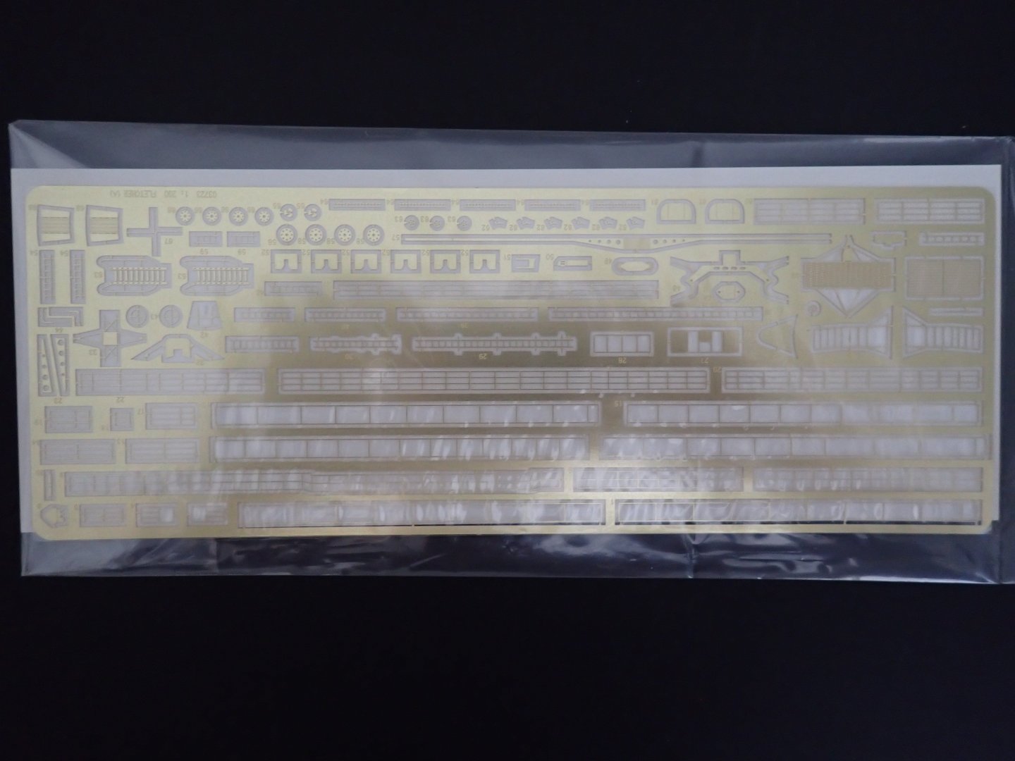
This is a quick presentation of the latest 1/200 kit from Trumpeter. I have two Japanese, one German ships at that scale and thought that I should also have one American vessel. I always wanted to build the kit from Lindberg about that famous Destroyer, but could not resolve myself to spend time on such a crude kit. When Trumpeter announced the production of the DD-445, it was worth investing into it (I got my kit from Squadron for less than $99.00). Of course, the Lindberg kit designed for flotation is much bigger, but the Trumpeter kit will fit nicely with the other ships I have. The box is very well presented and organized, as is the case with Trumpeter. As is the case with Trumpeter, the instructions comes with a nice double pages, showing the colors and paints required to finish the model. Two schemes are proposed: The first page shows all the parts available in the kit: A large sheet of decals is provided: Hull and deck are pre-packaged together: Two sheets of PE and a length of chains, are also included: I believe this little kit will be popular among the modelers. Trumpeter was planning to provide three different types of destroyer of that same class. We will see if they implement that idea, all the way. Yves


-
- 10
-

-
Great simplification of the hull building, by keeping it as a waterline model. Then the difficulty will be to recreate a realistic sea for the base. Yves
-
The Mossy Shipyard by Bryan Woods - 1:1
yvesvidal replied to Bryan Woods's topic in Non-ship/categorised builds
I am curious as why you placed a plastic tarp between the dirt and the concrete. I have not seen that done in NC, where I live. Yves -
I like the color. I am doing a Chebec using cherry wood and the color is similar to that one, just more pale. Yves
-
That is a badass car, for sure. Great model, Craig. Yves
-
Tilt Top Table by kgstakes - 1/12th scale
yvesvidal replied to kgstakes's topic in Completed non-ship models
Very cute table. -
Wieslaw, I have two questions for you: Which forum did you use to publish your work in Poland or northern Europe? I would love to follow your work there and get into more details. Is it the Polish Koga Models forum? I hope you have kept a library of all your 3D designs for that battleship in 1/200. Is this something you may consider sharing with other modelers or even sell? The Halinski card kit may be a good base to start this model, but all your added pieces are turning it into a museum quality model. Thank you for your time. Yves
-
Fantastic workmanship Wieslaw. Just amazing. I could not believe my eyes when I saw your "paper" hull !!! That is just incredible. The blending of "paper", cards and 3D printed parts (that you are designing yourself) is the way to go and your model will be ten times better and more precise than anything Trumpeter could come up with, if they ever decided to do a Fuso battleship. You truly are an artist and I hope you find the stamina and dedication to finish this incredible and so unique model Yves
-
Craig, could you specify what kind of paints you are using? That glossy black is fabulous. Yves
-
I believe that a couple of updates are overdue. After building one side of the deck and hull, it was time to offer some symmetry to that model: The wale are carefully positioned to match as much as possible the other side and the planking follows. However, you do not want to plank too much and must stay below the gun deck level, for ease of assembly: Next is the construction of the gun deck: Again, for sturdiness and longevity, the supports are pinned on the main deck. Below, the grates are installed and the delicate planking of the gun deck can start. Starting from the rear and slowly moving to the bow: Once the gun deck is fully planked and we are happy, we can complete the planking of the side of the hull, all the way to the railings: A couple of details: the rear deck, is not finished yet. The base of the rear mast is not installed yet, and will be fine tuned later on, when building the quarter deck. However, the frames that could not be installed before (you would need the Holy Spirit to hold them in place) are now added as shown in the picture below: There is still plenty of work to be done to file to the right dimensions all the gun ports, on the starboard side and place some more planks, but it is moving along, slowly but surely. The Port side is almost finished...almost. Hope you enjoy that quick update. Yves


- 185 replies
-
- 22
-
-

-
Your neighbors must be envious to see that beautiful Carrera GT in your driveway. Fantastic model Craig. Yves
-
Craig, I can see a trophy at the next contest.... Yves
-
Such a clean work, as always. YVes
-
Truly impressive and remarkable. I admire your tenacity and sense of perfection, Rob. That model truly looks like the real thing and if it was sitting outside with the correct backdrop, you could fool a lot of people. Yves
-
Fantastic improvement Kevin !!! Yves
-
You are correct, strengthening the hull. It is necessary and I remember doing the same on my R/C model. Yves
-
I feel your pain, Rob. The results are glorious. Yves
-
Maybe, you could display the car with the bonnet open, showing all the marvelous work you did on the engine. I agree with you that such bump is frustrating, especially after spending so much money and efforts to make it work. Your model remains a marvel and a master piece, no matter what your mood may be at this moment. Honestly, it looks just fantastic. Yves
-
Great introduction of these legendary ships. I am currently working the wooden version of that model, designed and created by CAF Models. It will be interesting to compare the two implementations, although I suspect that you will go a lot quicker than I. The last picture is from a model from the National Marine museum in Paris. I have been drooling on it, while painstakingly gluing the various pieces of wood, included in my kit. Yves
-
I can't wait for some paint to blend all these modifications into what will be the most precise and prototypical 1/200 Titanic hull on the market. Yves