SJSoane
-
Posts
1,655 -
Joined
-
Last visited
Content Type
Profiles
Forums
Gallery
Events
Everything posted by SJSoane
-
 HI everyone, Well, I confidently started out trying to make the gun insignia with photo etch. I simplified the George III image, but when I print it out at 3/16" inch scale (about 1/8" long), even the simplified detail disappears. And I am not yet sure how much detail will even show after I sort out the etching process. Not so confident now! Maybe there is a better idea.... Best wishes, Mark

-
Thanks, Sherry, for the thoughts about the resin. I'll proceed cautiously.... Best wishes, Mark
-
Ed, I don't know how you managed to resist the temptation to show the other hull all this time. It looks great from afar.... Mark
-
Siggi, Phenomenal photos. It feels like we are on the actual ship. Mark
-
Hi Sherry, I was just about to start working with casting resin cannon, and read your comment. What kinds of problems did you encounter? Best wishes, Mark
-
Hi Mark, It worked for me, drilling the hole first. I then turned it at the highest RPM on the Sherline lathe, with a very shallow cut across the area with the drilled hole. I was also using the pointed cutting bit, which presumably has a smaller surface to catch if it would. I was only aware of a smallest change in sound, but no sense of anything catching. It seemed to work without difficulty. Best wishes, Mark
-
Thanks, Nils, Siggi and also Ed. Nils, I appreciate your comments, thanks. Ed, I got an email telling me of your post, but it does not show up in my build log on my computer. Strange.... Thanks for the information about shrinkage in casting. I confess I did not even think about it when I was making the master, although I was vaguely aware of it from reading about manufacturing processes years ago. I'll see how much shrinkage will happen in 2", with lead-free pewter. I may moderate my quest for perfection, since I don't fancy right now turning another master. At 3/16" scale, a quarter or a half an inch is not really perceptible, I keep telling myself... Siggi, thanks for the pictures of the barge. I admired that every time I visited the National Maritime Museum. I haven't been in years to Greenwich; is it still in the main building at Greenwich, or has it been moved to Chatham? Best wishes, Mark
-
Very nice, Siggi. What are the white objects in your moulds? I have been thinking about painting my gun carriages red, and your photo just convinced me. They are red in most 18th century models I have seen that have guns. Best wishes, Mark
-
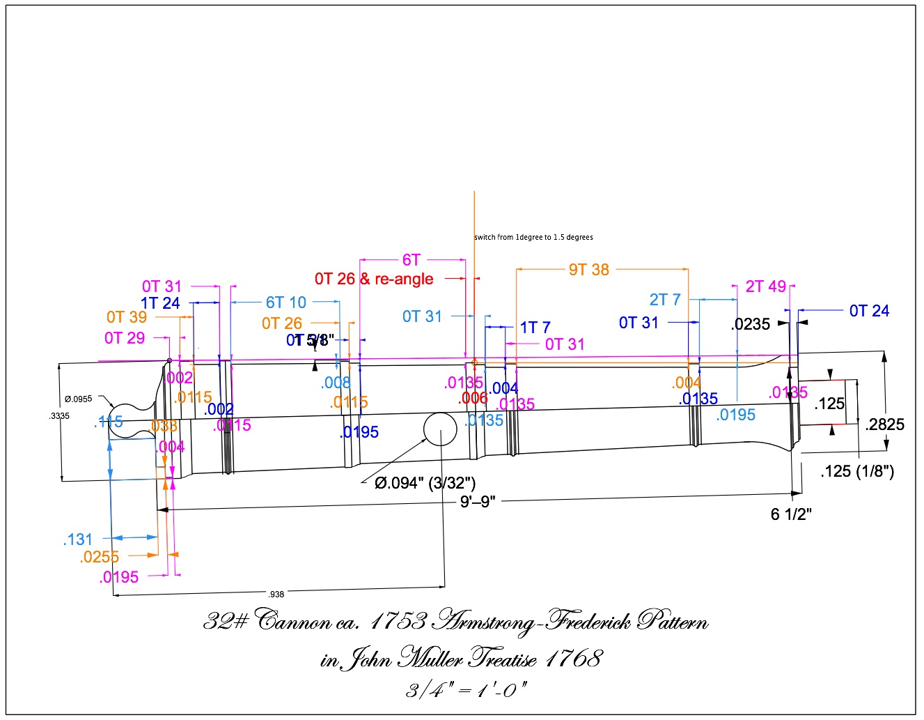
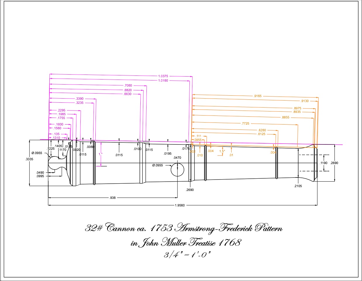
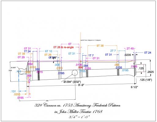
Dear Greg, druxey, Siggi, Grant and Ed, Thank you for the kind comments. It took me almost a week of long days to produce this one master cannon, and your support on this website kept me going at times. When I first laid out my "recipe" of dimensions, I did not account for the fact that the pointed cutting bit has an angled face. Cutting up to the line on the fine moldings meant that I had already cut away half of its thickness. So If you look closely at the drawing (actual sizes on the lower half, the cutting dimensions on the upper half), I thickened up the various moldings so that when I cut to the line, I ended up with the right size. But I only got to this through a number of failed trial and error recipes. I confess it got tedious! I did try switching cutting bits to a face perpendicular to the moulding on each side, but then I got so lost in where I was. I finally had to figure out how to use a pointed cutter for the entire length. Greg, I am an admirer of your own machining skills, and I can share with you that the angle gauges did have to come into the shop only after I got very tired of setting angles by trigonometry (moving the cutter in the X dimension down a set length, then dialing in the Y direction to see if it hit the blank forming a 1 degree triangle, then adjusting and doing it again). The manual method was OK at first, but not after so many failed trial and errors. That was one of the reasons it took me so long to produce this master. Siggi, I know how it feels to discover information after you have completed something that is now out of reach for repair. I have a few of those in my project that I keep thinking about. But I looked at your photos, and your cannon look great to me. Also, I discovered that there are a number of variations on this cannon pattern, so who will know! Ed, I have not cast anything before, and I am going to follow the directions in David Antscherl's volume II of the Fully Framed Model. I found lead free pewter at a local jewelry supply, and will see what happens. I also just bought some Micro Mark casting resin, to see how this turns out in comparison to the pewter. I would give a special acknowledgement to Michael Mott, whose magnificent machining precision on his skipjack engine inspired me to work a little harder at getting this as right as I could, within my own skill level. Best wishes, Mark
-
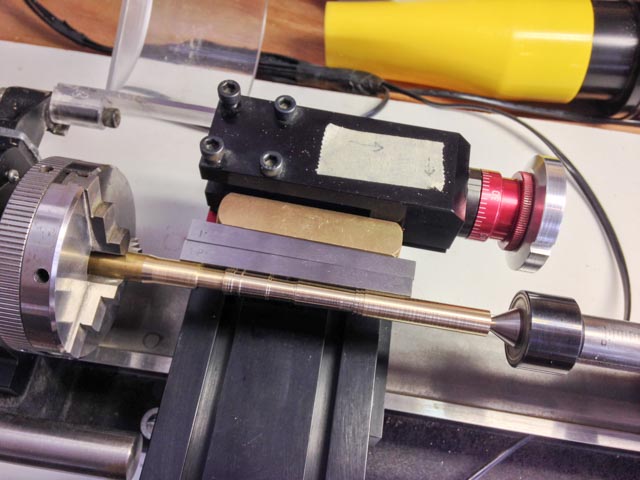
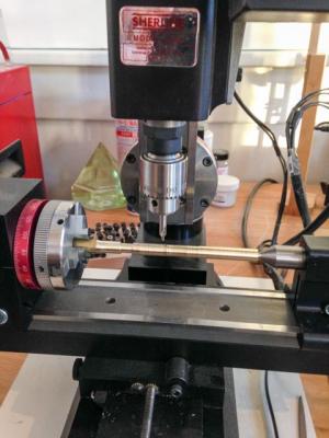
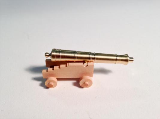
Hi everyone, Well, after a number of rejects, I finally made a master 32 pound cannon for casting. A few details. First, I decided to use the Sherline angle cutting device for the angled cuts, since the angle to the hind of the second reinforce is different from the angle ahead of the reinforce. I used some very handy angle gauges to set the device to the 1 degree and then 1 1/2 degree parts. This was infinitely easier than calculating the tangents of the angles, and then trial and error setting the angles. The second photo shows setup using the 1 and 1/2 degree gauges. I have a digital readout on my lathe, but this does not work on the angle device. So I had to count turns for distances. To facilitate this, I adapted an old Sherline hand wheel that can reset to 0, turning it down to fit the angle device. This helped enormously with incremental counts down the length of the cannon. And then I drew up a recipe (fourth photo), converting actual scale lengths to numbers of full turns of the hand wheel plus numbers of increments in part of a turn. You can see this in the photo as, for example, 9T 38, which means nine full turns plus 38 increments. Each horizontal and then vertical cut is color coded the same so I could keep track of where I was. Inspired by Michael Mott's machining, I used a center bit in the mill as seen in the first photo, for drilling the hole for the trunnion. This helped keep the hole accurately located while drilling into a curved surface (the trunnion is off center by half its diameter). It worked perfectly. Thanks, Michael! I intend to cast these, so the muzzle mouth has a dowel on it, onto which I will attach a funnel head for making the mold. At last, I can think about making molds! All for now, Mark

-
Ed, I was taken by your comment that the clarity of the design emerged as you put it together. I think it is one of the joys of scratch building a complex design, to suddenly discover in the making of something how it was logically put together in the first place. It always gives me a deeper appreciation of our ancestors, and the deep design traditions in which they worked. Best wishes, Mark
- 3,618 replies
-
- 7
-

-
- young america
- clipper
- (and 1 more)
-
Michael, astonishing. I would not have believed it possible, and yet we saw it step by step. You are an inspiration! You mentioned hard buttons several times for guiding your filing. How do you make those? Best wishes, Mark
-
Michael, That looks like a full size lathe, making such small parts. I am impressed! When you use a slitting saw in the lathe, which had never occurred to me as a technique--thanks for the insight!--do you shim up the stock to the center line, or it doesn't matter? Best wishes, Mark
-
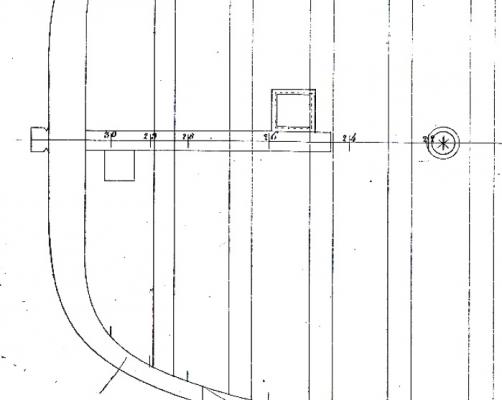
Hi Siggi and druxey, Thanks, I never noticed the lady's hole scuttle did not have a coaming. My Bellona section shows no coamings for any hatches or scuttles, and so I assumed all of them would have coamings, including the lady's hole. But once you pointed this out, I looked again at the Bellona gundeck plan, and it does indeed show no coaming (see below). I have ceremoniously thrown my coaming into the scrap bin. One less piece to glue on! Best wishes, Mark
-
Hi Siggi, The photos are terrific. You can almost imagine being in the real ship. I clicked for a closeup of the guns in the third photo, and saw the four legged table towards the stern. The turned legs are astonishing! The barrels, sea chests and pails give a very good image of life on the gundeck. I see what you mean about the hanging knees cast to avoid the gunports. You are providing a roadmap for me, when I eventually get to these on the Bellona. So how did you resolve the question of the hatches on either side of the knee? I see a grating on the one to port, but cannot see the one to starboard. Does it also have the same grating, or did you do something different there? Best wishes, Mark
-
Hi Michael, Great tutorial on drilling small holes. I searched around for better drill bits last year, and thought I had made a great discovery of carbide drills with common shank sizes to fit my Foredom collet. But they all broke on the very first use. Back to the steel wire bits. When you say, buy the best you can afford, what brand are you using? Best wishes, Mark
-
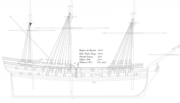
Thanks, Christian, I'll post a few more drawings when I have a little more to show. I am drafting in CAD right now to clarify some issues coming up in the build, so they are not yet in a finished form. But someday I may develop a full set of the drawings, just because it would be fun to do! Alex, I read your comment again, and realized that you were talking about the unusual planking butt in the main wale. I was just at a workshop with David Antscherl, and he noticed the same thing when I showed him the drawings. It turns out that I faithfully copied the planking arrangement for the main wale from a NMM photo I have of the original 1760 Bellona model (the one I show photographs of earlier in my build log). It does seem odd, and not the strongest way of planking this wale. Since this particular model shows two different ways of framing, port and starboard, perhaps this was also a way of showing a proposed change to wale planking? I decided when I started this project that I would be as faithful as I could to the original 1760 model, and so I decided to include this distinctive detail. As it turns out, I have discovered a number of discrepancies between this model and the drawings done at the same time. A very complex history! I have not been able to look closely at the 1780s model of the Bellona, to see if the main wale in that model has this same pattern. Best wishes, Mark
-
Thanks, Alex, the shift of the planks, while avoiding gunports, has been challenging for me! Best wishes, Mark
-
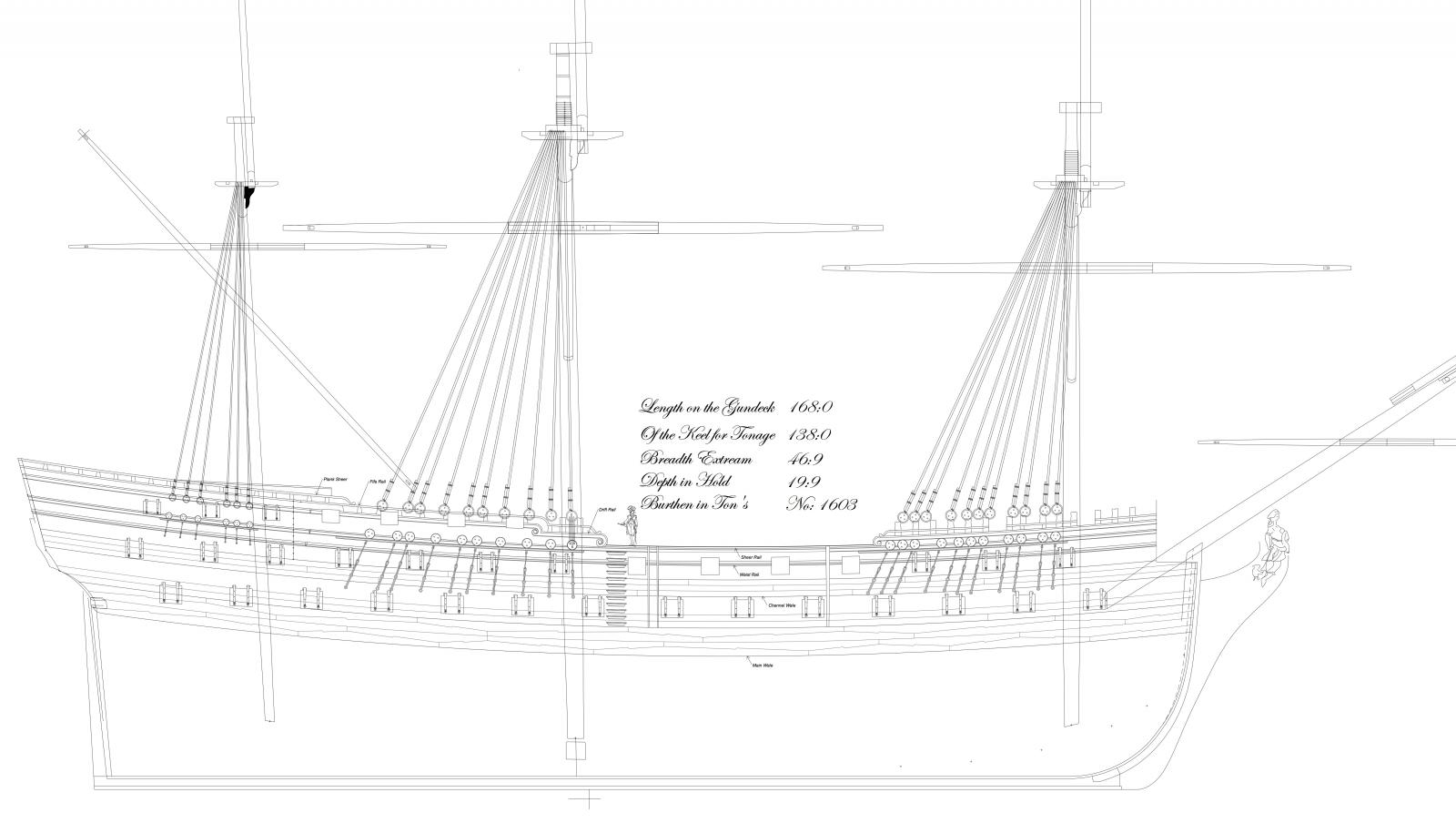
HI everyone, I forgot to mention that my gun drafting came as part of re-drafting the Bellona in CAD. Here are a couple of screen shots of progress so far.... Best wishes, Mark
-
Hi Siggi and druxey, Here is the passage regarding the three sections to a barrel: "It is a universal custom in Europe to make the guns with reinforces; that is, they are, as it were, made of three frustrums of cones joined together, so as the least base of the former is always greater than the greatest of the succeeding one, whereby the metal breaks off in two places on a sudden, a the reader has seen in the construction of pieces given here before. But since powder acts uniformly and not by starts, it is hard to judge from whence this ridiculous custom has arisen, which seems to be as old as the invention of guns....Since then powder acts gradually and not by starts, there should be no breaking off in the metal..the piece should be cylindric, from the base ring to the end of the charge, and from thence, by the nature of the explosion, a curve line bending inwards quite to the mouth of the piece..." pp 38-9. He is describing the guns as they came to be in the early to mid 19th century, where the outer barrel is a smooth curved surface not broken by these old mouldings. And he was writing maybe 75 years before this became common practice. Best wishes, Mark
-
Hi Siggi, Here is the diagram from Muller's Treatise on Artillery, from Google books online. It would cause it the gun and carriage to jump up, since the line of force is along AB, and it is resisted at D. Someone more knowledgable than I am would need to say if this would make any difference at all. Best wishes, Mark
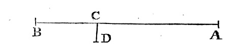
-
Thanks, Mark, druxey and Siggi. It is always nice to get some affirmation on those many moments when you have to make educated guesses on historical information. I forgot to mention that the Muller book was exceptionally interesting as a glimpse into the early dawn of the industrial age in Great Britain in the mid 18th century. He dutifully reports on the proper, historically received proportions for guns. But he then complains about how arbitrary these are, not based in reason or fact. Some examples: After explaining that the proportions given apply to all sizes of cannon, he says "The reader may easily perceive the perplexity of these constructions, arising from the different scale that are used with the least necessity. That the greatest part of the mouldings should have the same dimensions, from a 3 pounder to one of 32, appear contrary to reason..." He then complains that experiments on a 24 pounder for weight of powder and distance and trajectory, were then extrapolated to other sizes of guns without then testing these. He also complained about the location of the trunnions so that the top of the trunnion is located at the center of the cannon. He said "...it is so absurd, that is is amazing no author or artist has thought proper to change it...to show the absurdity of it, suppose AB to present the center line of the bore, and CD the distance of the center line of the trunnions from that of the bore. Now because when the piece is fired, the explosion acts against the breech B, and makes the piece recoil, but being fixed to the carriage by the trunnions, endeavours to turn about the point D....the piece therefore acquires a pendulous motion about the center D." And he complains about the tradition of breaking the cannon into three different diameter cone shapes (first and second reinforce, chace), because powder does not explode in stages but rather continuously, suggesting a design for a cannon with no breaks in its profile. I think we see here the first signs of challenging traditions handed down for their own sake, and proposing a more scientific view of designing ordnance. Of course, this kind of thinking eventually leads to artifacts more functional than beautiful. Or, perhaps we eventually find a different kind of beauty in more functional objects. But then I wonder why so many of us are drawn to the beauty of these pre-Industrial Revolution artifacts? I love how history provides endless opportunities to ponder the great imponderables! Mark
-
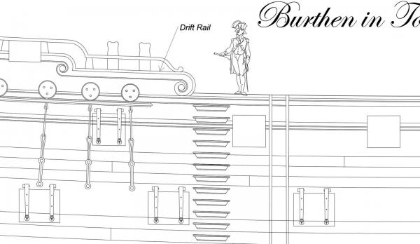
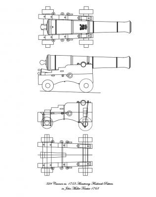
Hi everyone, A long time away from the shipyard. I last got the deck clamps in before the winter humidity in Colorado drops dramatically, and I will have to wait until spring to start on the main wales when the humidity comes back to match what it was when the clamps went in. So, I am backing and filling for a while.... I learned about sail making from Greg Herbert and David Antscherl's workshop this December, and may post some pictures of my sail efforts for the Bellona at some point when I have something to show. It was a terrific workshop. I highly recommend it. In the meantime, I am working on the 32# guns for the Bellona's gundeck. I spent a fair amount of time researching guns that would be appropriate to ca. 1760. I may have this wrong, but I believe the guns at this time were based on a pattern developed by Surveyor General of Ordnance, General John Armstrong, in the 1720s. This was updated slightly by Charles Frederick in 1753. And the dimensions were given in John Muller's Treatise on Ordnance of 1768. Using Google books, I was able to reproduce the gun and carriage for a 32 pound cannon. The details are a little different from ones more commonly found in the 1770s in a number of modeling books. The most obvious are that the cascable is shorter, with a compressed set of moldings behind the base ring. Also, the transom on the carriage is vertical over the fore axtree (which looks very much easier to build than the angled ones seen later). And the stool does not sit on a thick bolster, but rather a rather thin vertical plank. It looks a little fragile compared to later carriages. I pasted my gun and carriage over a scanned image of a cross section showing the guns in Falconer's Dictionary of the Marine from the 1760s. The Armstrong/Muller details lined up almost exactly with the Falconer drawing. The only difference is that I had to reduce the height of the carriage body by about 1 1/2" to get the cannon at the right height relative to the gunport, matching the Falconer height (which is the same as the Bellona's). Also, the Falconer drawing shows an elongated neck for the ball at the end of the cascable. I could not find any other examples of this in other resources, so I stuck with the drawing in Muller's book. Interestingly, the drawing in the Muller book does not match the text, regarding the length of the cascable; the text calls for something longer than the drawing shows, probably getting closer to Falconer's drawing. But I could not draw this convincingly without further information. The text also explains a method for determining the length of the body, which does not match the length given in a table. Research from primary sources sometimes has its challenges! I spent some time working out the dimensions for the cannon, relative to one origin. You will see one set of dimensions in purple, aligned to the first and second reinforce which is a 1 degree taper. The second set in orange aligns with the chace, whose angle is 1.5 degrees. I hope to use this to turn a master on the lathe, and then try casting the 28 guns required. Stay tuned! Best wishes, Mark

-
This is so inspiring to see, Michael. I didn't know such a thing was possible. Merry Christmas! Mark