SJSoane
-
Posts
1,655 -
Joined
-
Last visited
Content Type
Profiles
Forums
Gallery
Events
Everything posted by SJSoane
-
 Hi Siggi, I don't have any more information than the photo of the Bellona. You make a good point that the pawls cannot work at the same time on two decks, because they cannot hit the whelp at the same time, with 5 on one deck and 6 on the other. If they were fitted on both decks, it could only be for the convenience of working the capstan on one deck or the other at a given time. Can you imagine one team yelling up the other deck, "don't worry, we will kick in the pawls if necessary".... Mark
 -
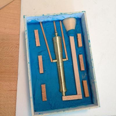
Hi Ed, Thanks very much for this help. I have 28 castings to do at this gun size, plus a few spares. I had originally ordered the 1 to 1 four hour set, which exceeded its shelf life by a long time, and I think I need to throw away at this point. I was just about to order some new RTV, and saw that MicroMark has a one to one one hour set; in light of your comments, can I assume that this would be too fragile for my intended run? And do you think I should go ahead and order the 10 to 1? I see what druxey is saying about floppiness with the rubber I tried so far, and perhaps the 10 to 1 would not have that problem. I will try the measuring by weight rather than by volume in a measured cup; it seemed fairly hit and miss by volume. Do you mean a regular kitchen hot plate and metal dish? I somehow assumed I would need more intense heat as in a propane torch. Thanks again, it is always comforting to be walking in the footsteps of great craftsmen who have been down this road before! Mark
-
Sherry, The comparison between the two is remarkable. That is an impressive piece of workmanship! Mark
-
Michael, So both you and Siggi have had experiences with metal flying around the room. I am beginning to understand that metal casting is a contact sport! Isn't it fun reflecting on those early life experiences that only later we can call character building...;-) Mark
-
Ed, It is such a joy to see your step by step tutorials. It is impressive how logically you approach each step, and then it seems self-evident. But not until we see you do it! Mark
- 3,618 replies
-
- 3
-

-
- young america
- clipper
- (and 1 more)
-
Hi druxey, Ed and Michael, Thanks very much for the advice. You have all had a lot of experience with casting, and this is invaluable for me. I will try the top down feed in my next version, and see what happens. I will first order some new rubber from MicroMark. I think the shelf life problem was working against me this first time. It was a little thick. How were you all heating the pewter? With a propane torch, or will a micro-torch do the job? Best wishes, Mark
-
Hi David, it is worth jumping into, and easier than I had expected. My initial failure just gave me more encouragement to get it right next time. Siggi, your English well explains the image of pewter flying around your shop! I hope nothing got burned. I have already purchased some pewter from a jewelry supply, and will likely try casting it in the spring, when I can go outside to heat it up. I am a little bit concerned about the weight of pewter guns, and the possibility that they could break away from their mountings long after I can no longer gain access to the deck. But I assume many before me have successfully managed this. Best wishes, Mark
-
Siggi, well spotted. I did forget the touch hole. Good thing I have to start again anyway! So, do you have a centrifugal force casting machine? I have seen those in jewelry catalogs. Mark
-
Gaetan, That is a beautifully crafted ropewalk. Can you explain a little more about the swivels? I don't see them in the first photo at the motor end. Is there only one, on the tail end with the trolley? Also, can you show the three legged top in more detail? Does it have grooves along the legs for the thread? And is the thread the Bokens linen size 110? Lots of questions, but I am fascinated with the quality of the lines you are creating. Mark
-
Remco, Your attention to this level of detail is remarkable, and so perfectly accomplished. Mark
- 1,215 replies
-
- 1
-
-
- sloop
- kingfisher
- (and 1 more)
-
Toni, Beautiful friezes. Like Remco, I have been pondering whether to paint directly onto the hull or use paper. You have shown how successful the paper approach can be! Mark
-
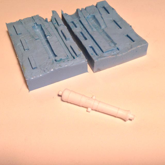
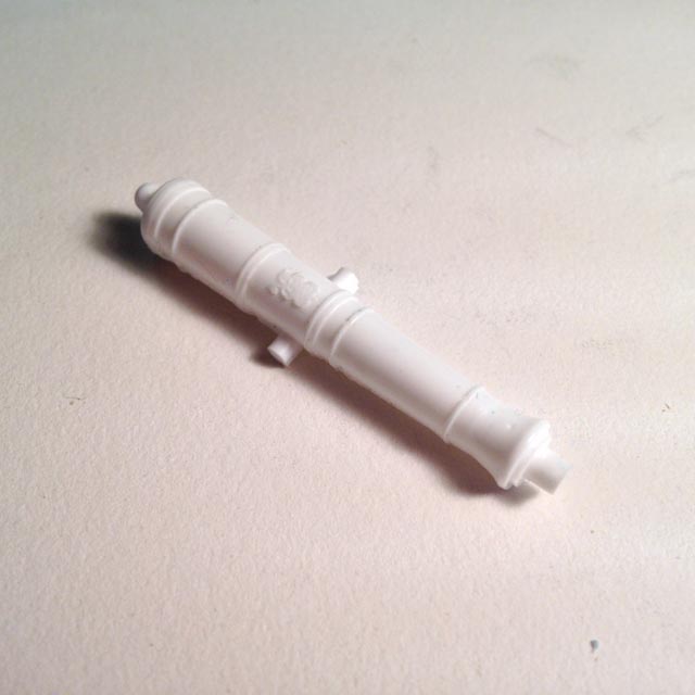
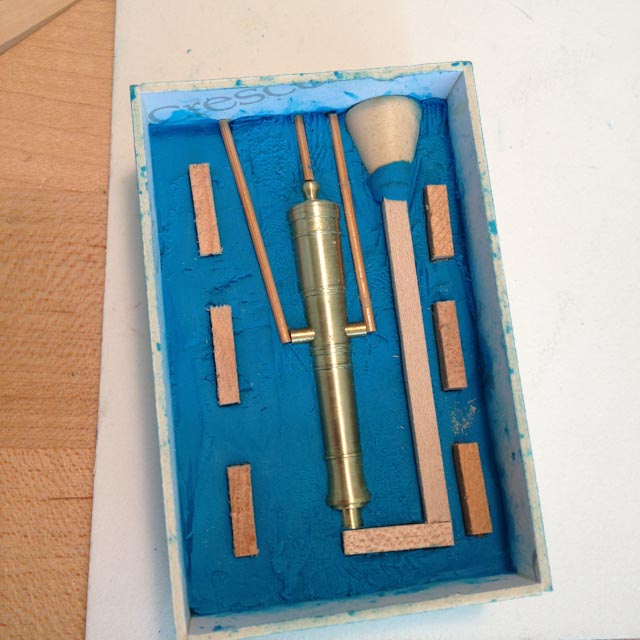
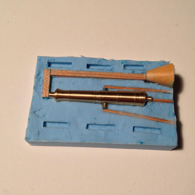
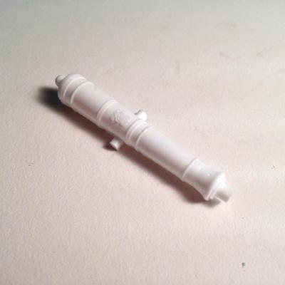
Hi everyone, I have managed to cast my first cannon, more by luck than skill. Many thanks to Greg Herbert for the cypher; I have yet to accomplish a photo engraved cypher myself. I learned a great deal, but will have to do this again, since the mould line between the two halves got a little ragged, leading to leakage and also a loss of detail at the join. Here is what I learned: First, I built the initial mould box taller than the clay, which was a mistake. I was digging around from above to try to level the clay, and to push it evenly against the master. In hindsight, I see that the clay needed to be more accurately pushed up against the master. I didn't, and the first pour seeped down into the areas where the clay was not fully against the master, leaving a thin "flap" that prevented the second pour from coming cleanly against the master. Next time, I need to build a first box at the level of the clay, then build higher walls to contain the first pour of rubber (the idea can be seen in the PDF about making moulds in the resources section of this website). Second, I was using MicroMark rubber mould material that was 18 months beyond its shelf life. I don't know what it is supposed to be like within its shelf life, but one of the bottle's material was very stiff to stir at first. Indeed, I did not stir it enough for the first pour, and as a consequence it took overnight to dry and did not capture the detail as well as the second pour. I worked hard at mixing for the second pour, and added some thinner. The fidelity to the master was significantly better. I used a bottom-up feed on the mould, with the understanding that the trapped air would be pushed out a vent at the top. I poured resin until I saw it bubbling out of the center vent. That method seemed to work flawlessly, with no captured air bubbles. However, I did notice a couple of pin holes in the top of the muzzle, which i assume were bubbles created when i poured the rubber onto the master. I poured a very thin stream rubber from over a foot above the mould into a corner, understanding that this would remove bubbles thicker than the stream, and that the material would slowly flow over the master. Worked almost, not quite! Perhaps my rubber material is too thick still, and needs more thinning. If I am feeling experimental, I might try a top feed and see if it makes any difference or causes any difficulties. A top feed would certainly reduce wastage on the poured material. (I am in no rush, since I am still backing and filling, waiting for the Colorado humidity to come up in the spring so I can get back to building wales at the same humidity as the internal deck clamps.) Back to the foundry for round two... Mark


-
Karl, The rope does indeed look like full size. Spectacular! Mark
- 662 replies
-
- 1
-
-
- bonhomme richard
- frigate
- (and 1 more)
-
Gaetan, Beautiful, and what a rich tradition of decoration in French ships! Mark
-
Hi Siggi, Yes, you are right, my mistake. The barrel is indeed 10 and 12 sided. Your method worked well! Mark
-
Michael, Very clever idea, sliding the blank progressively out of the collet chuck to keep the cutting close to the chuck. So obvious once you mention it, but not obvious enough that I ever thought of it. We continue to learn from the master! Mark
-
Michael, your work continues to show the art at a level of sophistication and skill that I would not have believed possible until I see it before our very eyes... Mark
-
Very nice, Siggi! I found it very challenging to cut the octagonal hole within the capstan head, to slide down on the barrel. You did it flawlessly. Mark
-
Alan I have been working happily at 1:64. The biggest challenge so far in terms of size was the capstans' whelps. But it is possible! Mark
-
Ed, I am also intrigued by your sculpting epoxy. What is the brand? Beautiful, inspiring work. Mark
- 3,618 replies
-
- 1
-
-
- young america
- clipper
- (and 1 more)
-
Hi Siggi, I echo Gary's question. Do you have any photos of making the small details? They look very good. Great photos! Mark
-
Dear Gaetan, Beautiful, artistic, exquisitely crafted. You are a master. I notice your vise for holding the carving. I have seen these vises, but never how they might be used. Very ingenious. Best wishes, Mark
-
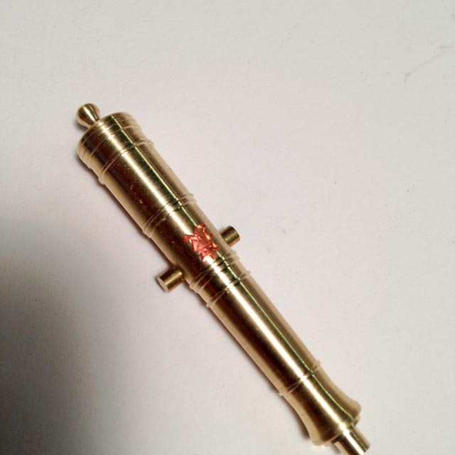
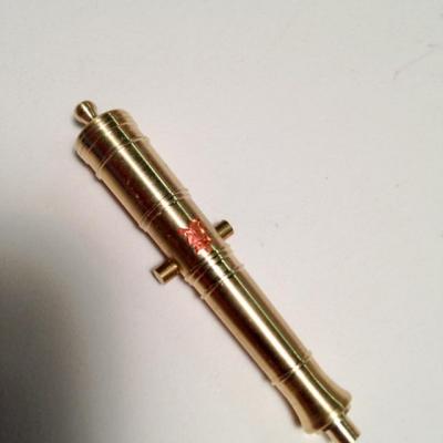
Thanks, druxey, that is a good idea. I spent the day trying fine wire, Fino modeling clay, and then some stick-on thin copper. None worked as well as the copper, which I show in a rough form here. I was thinking about casting a copy of the cannon, then adhering the thin copper to the barrel, and then engraving and cutting while it is in place. But before trying that, I will try the acrylic matt. I am learning that, at this scale, it is an impression of detail, not as defined as I thought at first. The thin wire and modeling clay were way too "chunky" for the scale of the detail and the cannon. druxey, any ideas on how I will transfer the pattern to the brass barrel? Of this this a case of free-handing with a fine awl? Best wishes, Mark
-
Thanks, Michael, this is a very good lead. I'll look up Doris' log, and track down some Fino in the morning. The etching was beginning to look like major overkill for one master.... Your machining continues to inspire me. I worked a little harder on my cannon master after seeing how you approached your project. Thanks! Mark