


wefalck
-
Posts
6,526 -
Joined
-
Last visited
Content Type
Profiles
Forums
Gallery
Events
Everything posted by wefalck
-
 Good to hear that you are safe. (More rural) Canada doesn't seem to be hit so hard (Canadian friends in Ontario assure me) compared to other parts of the world, but one never knows. I go a bit concerned, as there had been no updates here on the train project either.
 -
Historically, the French coast and some of its hinterland from the Spanish border up to roughly the fortress of Salses belonged culturally to Spain, being part of the 'Kingdom of Mallorca', which included parts of modern Catalonia. The Pyrenees weren't quite such a cultural divide as one may think, particularly along the coast, where they could be easily crossed. If you search for 'Sorolla boats' you will get various pictures by the Valencian painter Joaquin Sorolla on these Catalan/Valencian boats, including them being hauled out by oxen.
- 72 replies
-
- 4
-

-
- fishing boat
- Barco Catalan
- (and 1 more)
-
Any progress on this front ? I also noticed that Michael seems to have last logged-in in mid-August. Hope everything is well ?
-
I love these small boat projects, the more so that we have a second home further down the coast from Catalonia. There, this sort of boat for beach-fishing was called 'oxen-boats, because they were hauled out onto the beach by a team of oxen, rather than a capstan. In France such boats were called bateaux bœf for the same reason. Just a question: as the boat is decked almost all over, why didn't you leave the bulkheads etc. in ? Less risk of breaking something and a more stable hull. You made just a passing reference to your sources. Could you please enlarge on them a bit ?
- 72 replies
-
- 3
-
-
- fishing boat
- Barco Catalan
- (and 1 more)
-
Not sure, what is going on there. The MSW seems to have changed the functionality of the site. I had problems attaching the pictures from my Web-site as I normally did. They did not show up with an http-link. As the system at some told me that http-links are not accepted anymore, I changed the link to https. However, my SSL-certificates is not valid anymore, as the provider changed their software and I couldn't renew it from my old browser anymore. I have to look into this whole story and probably need to change my DSP, as they also refuse to co-operate with my old browser (and I can't upgrade, because then I would need to upgrade the MacOS and then I would need to buy a whole lot of new program licenses and ... this become really a pain and we are getting trapped in the money-generating machinery of the software industry more and more. I will see, whether I can upload my pictures to MSW, which is something I normally don't like to do.
-
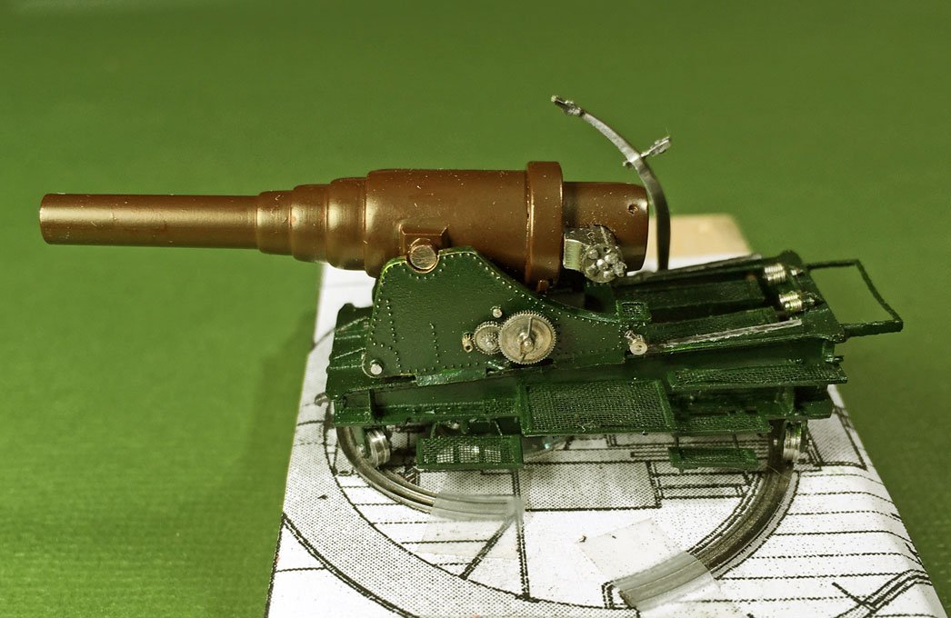
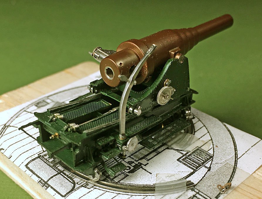
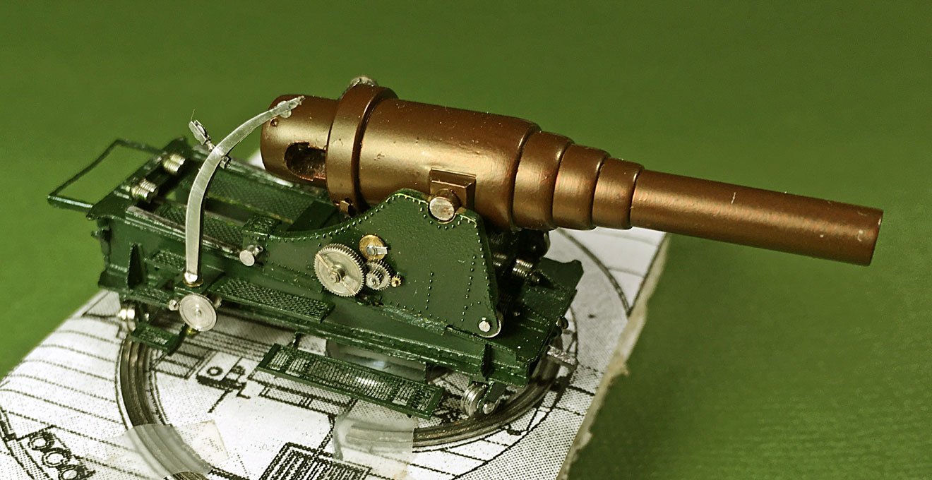
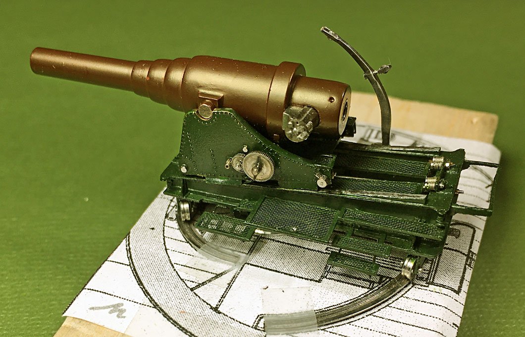
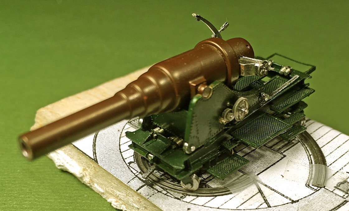
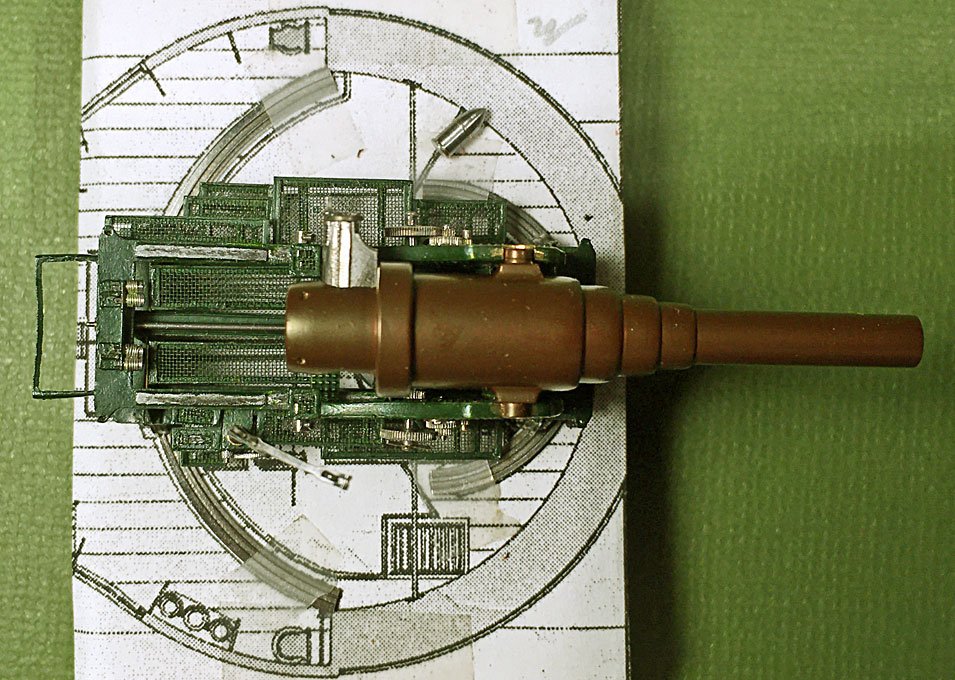
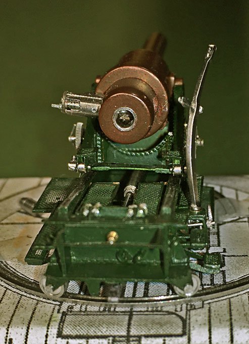
Thanks for the kind words ! ************************ Assembly of the gun Slow progress with steps forward and backward ... and a lot of sweat and bad language ... All parts temporarily assembled had to be taken apart for painting first. After selecting a green for the carriage, all the parts were given several light coats with the airbrush until a uniform colour and sheen was achieved. Not so easy on some of the complex parts. After letting it thoroughly dry, the paint was scraped off from those parts that are meant to be bare metal, but could not be masked off, due to being difficult to access. The assembly then proceeded from the inside out on the lower carriage. First the parts for the hydraulic recoil brake were installed. I decided to deviate from the prototype and not to install the protective tunnel over the piston of the brake in order to show the metal-work. I think this small bit of artistic license is permissible. All parts were put together with small blobs of zapon-lacquer, which dries up quite invisible. Next the spring buffers were installed. Putting in the tiny hexagonal nuts required a very deep breath each time. Flipping the carriage over the caster-wheels were put back, but this really taxed my patience. The wheels are held in place by little flat-head pins inserted from both sides. A simple through-pin would have been easier to install, but wouldn’t be quite prototype fashion. The lower-carriage was very difficult to handle due to the flimsy and delicate grilles and steps. One was broken off in the process, but luckily attached nicely again. The rail on which the upper carriage runs would be bare metal. Here the limitations of using cardboard as structural element shows its limitations. If I had used etched brass parts, I would have chemically tinned them before assembly and now could have just scraped off the paint or masked the area before painting to reveal the metal. Now I had to simulate it with paint and a soft lead pencil. I am not entirely satisfied with the result, but can’t do anything about it now anymore. Overall, I am somewhat ambivalent as to the merit of using cardboard. The surface and cut edges simply are not as smooth as those of metal or plastics, such as bakelite paper or styrene. Unfortunately, styrene could not be cut with my small laser-cutter. When proceeding to the upper carriage, I noticed a couple of mistakes I made years ago, when putting it together. Two of the transversal members were installed at a wrong place. The wheels of the carriage would have not touched the rails otherwise. When trying to rectify this, the whole assembly gave, but luckily I managed to put it back together without permanent damage. Another issue also arose: one should not work from drawings alone, particularly in a project that streches so long as this one. It turned out that the carriage was a couple of tenths of milimeters to narrow and would not fit over the lower carriage with its guiding plates. I should have properly verified this, when developing the parts for the lower carriage. With a bit of bending and tweaking it could be made to fit, but cobble-jobs like this leave parts behind that are not as crisp as they should be. Painting the gun barrel turned out to be a major nightmare. I did not want to prime the steel in order to not loose its metallic appearance. Usually, acrylic paints dry so fast that there are not serious issues with rust formation. When I first applied the first coat it looked ok, but the next morning it had developed a mottled appearance. The same phenomenon reappeared after each coat, but somewhat less. I attributed it to the fact that the bottle of paint was actually almost 25 years old and it had not been sufficiently mixed. In the end I cleaned off the paint and began again, but with the same result. Once more I took the paint off and then sprayed it, but without agitating the bottle, thinking that some of the pigment might have coagulated – same result. Finally, I decided to lightly prime the barrel with zapon-lacquer to isolate the steel. This forms a very thin and virtually invisible layer. This did the trick, but the priming was not done carefully enough and some spots were left bare – with the result that those areas appeared mottled again. I tried dipping, but this leaves a too thick layers in corners etc. Eventually, I managed to obtain a reaonably even layer – one has to work very fast and going over areas already treated is virtually impossible due to the rapid drying. It is also very difficult see, whether one has covered the whole surface. In conclusion, I think the pigment of caput mortuum, which probably is the mineral haematite (Fe3O4) has reacted with the steel (Fe0) leading to the mottled appearance. However, I managed to reproduce the appearance of the barrel of the demonstration model in Copenhagen reasonably well, considering the small scale. A few of the flimsy and easy to break off details have not yet been installed and some levers to work the mechanisms still have to be fabricated. The close-up photographs also show a lot of dust and fluff that need to be cleaned and that the paintwork has to be touched up here and there. To be continued ...
- 935 replies
-
- 21
-
-

-
With a bit of 'photoshopping', you could probably blend her into the river ...
- 599 replies
-
- 3
-
-
- sidewheeler
- arabia
- (and 4 more)
-
I think what amateur saw was something like this (No. 238): Source: LEHNHARDT (1895) 'Takelungs- und Ankerkunde", Plate XX
-
Modern cars don't seem to have 'frames' anymore. I believe the VW beetle (and the VW Kübelwagen = Jeep) was one of the first to have been built with a 'self-suspending' body, where chassis and body are integral parts. The 2CV wasn't quite like this, but had an underbody made from pressed steel panels. There were some stiffening 'stringers' as well. Mine suffered from rust at some stage and the road safety inspector poked a hole through it with his screwdriver. They cut out the rusty bit and welded-in some sheet metal, as the structural parts were not affected.
-
‘Universal’ Primer
wefalck replied to CTYankee's topic in Painting, finishing and weathering products and techniques
I love shellac and have used it a lot over the past 40 years or so on furniture and modelling projects. However, I would not necessarily call it an 'universal' primer. Its applicabilaty depends very much on what you are applying it to -> compatibility. Bare wood is ok, but as soon as you may have applied some putty or filler, the situation changes, when these are soluble in alcohol. Dito. any other surfaces that are attacked by ethanol. Sometimes, it is desired that the primer attacks the surface, because then it is able to key in stronger, one of the main functions of a primer. However, particularly when applied by brush, you may bring so much solvent onto the surface that you are softening and distorting it. Tests are always advisable. -
‘Universal’ Primer
wefalck replied to CTYankee's topic in Painting, finishing and weathering products and techniques
Paints are funny things and a lot can go wrong, when one begins to mix different things. A stirred paint is a (usually) carefully designed suspension or dilute gel of pigments in a mixture of 'medium' (e.g. lineseed oil) and solvent (e.g. turpentine). If you change the ratio between medium and solvent, the suspension can break down, it flocculates. Many commercial paints are quite forgiving as to the ratio as long as you use the right solvent or medium. If you are adding a fourth component to the system, i.e. a different solvent, a lot of things can happen: the paint may coagulate, the the medium breaks down with the consequence that the paint does not 'dry' or bind (the pigment dust off), etc. This is why insisted on the compatibility in the other posts. Such things can also happen, when certain paints come into contact with certain incompatible surfaces, e.g. some metals, such as copper, or different primers or other types of paint. The new paint will physico-chemically react with the surface, which can lead to its breakdown. -
I think there are two simple geometrical answers to the question - which doesn't mean they are easy to achieve. However: - the rabbet has to be so deep that the planking lands on the keel/stem without step, i.e. neither the planks nor the keel may be proud of each other - the included angle between the two surfaces of the rabbet should be around 90"
-
Vain hope ... somehow tools and materials have the desire to fill all available space on a work-surface ...
-
Oh, I forgot, yes they got the wood from there. The Lebanon cedar still is a pretty knotty wood ... and there is a chicken-and-egg-problem: you first to have ships to import the wood ...
- 158 replies
-
- 1
-
-
- byblos ship
- Egyptian
- (and 1 more)
-
Only just now discovered this project ! Excellent rendering of the sewn technology. The old Egyptians must have had a hell of a time to make a ship out of the mediocre and small pieces of wood that was available only in their arid area. I gather the shipyard slaves would have loved to have a CNC-milling machine, considering that all those grooves and mortices had to be cut with bronze tools.
- 158 replies
-
- 1
-
-
- byblos ship
- Egyptian
- (and 1 more)
-
It was an air-cooled boxer-engine, like on BMW-motorcycles.
-
Protective topcoat over blackened brass?
wefalck replied to Mike_In_RI's topic in Metal Work, Soldering and Metal Fittings
You must have used bad shellac then. Good quality shellac does not really yellow. Or, some stain from the wood has diffused into the shellac ? -
Very nice paint and weathering job again. It slowly comes together - or perhaps I should say falls apart prototype-fahion I found that very dilute acrylic washes, build up in multiple layers, give nice weathering and toning-down effects. As long as the paint is still humid, if can be washed off easily with a lot of water, if one doesn't like the effect. Once dry, of course, it is permanent. Unlike some inks and (fresh) oils, these washes are not attacked by subsequent washes.
-
Another conclusion: no carpets under work areas, particularly where liquids are used (I am not talking about oriental rugs under dining tables ...;) ). If you can't remove the carpet, put a hard surface over it under the worktable and where your chair is.
-
Accurate Triangle metal square
wefalck replied to michael101's topic in Modeling tools and Workshop Equipment
If I understood correctly, you are not actually lloking for a highly accurate triangle/engineer's square, but rather a way to set cutting tools (e.g. saw blade, sanding disk, etc.) square to the table with sufficient accuracy. It would be helpful to think about how much accuracy you actually need. Something with test certificates seems to be completely over the top for setting woodworking tools. In normal workshop practice standard engineer's square should be perfectly adequate. Their squareness is easily qualitatively tested as described by someone above. -
AL L'Hermione - LEGO jig for alignment of stepped masts
wefalck replied to Spike1947's topic in Masting, rigging and sails
Not a bad idea ! The only thing that would worry me a bit is that the LEGO-pieces would not be resistant to solvents. Gave my big childhood box of LEGO away to a little boy whose mother helped my mother to care for my father in his old age (not having children of my own), but kept my meccano set (the German equivalent of it) for making experimental machinery. -
The answer probably is that almost everything inside a ship at that time was moveable, except perhaps for some deck pillars. So stairs could be moved out of the way and hatches covered with gratings.
-
Any conclusion on this ?
-
On first sight, this indeed looks like an 'open heart'. However, the fact that the internal opening is round is a bit strange. Normally, part on which the lanyard rests would be straight, perhaps with shallow grooves, to make sure that the individual turns of the lanyard do not check each other. In the present configuration the lanyard turns would have the tendency to squeeze each other, thus making it difficult to set it tight. One would need to find similar images in the 19th century literatur to corroborate this shape of 'open heart'.