


wefalck
-
Posts
5,571 -
Joined
-
Last visited
Content Type
Profiles
Forums
Gallery
Events
Everything posted by wefalck
-
... or a close shave 😆
-
I think your rope is untreated hemp for one. Another point is the quality of the hemp as such. I gather today they have to take what they get, while in the old days certain regions specialised in the production of particularly long-fibred and smooth hemp, for instance certain provinces of Russia I believe and also in Germany. The second point is the preparation of the hemp, which is quite elaborate to obtain only the long fibres, while the rest goes to waste. The third point would be how careful and tight the initial spinning was performed. Your example doesn't seem to be particularly tight. The rope-maker also goes along the rope in making with a rough cloth to rub off loose fibres. I seem to have seen rather smooth, tighly twisted ropes. So in essence, at any of our model scales one should really see any fibres sticking out. Many people now use synthetic fibres that are essentially endless and where the problem of 'hairs' sticking out does not really occur.
-
 I love it ...
 -
Another material I used for blocks and that works well is phenolic resin board, as used for circuit boards. It is brown, quite easily available in thicknesses of up to 3 mm in electronics shops. I am cutting strips from the boards with my circular saw. It sands and polishes well. Unfortunately, paper-based phenolic resin rods do not seem to be available, only those with cotton fabric and then only from 8 mm diametre upwards. The phenolic resin has the advantage of being heat resistant, so that one can solder fittings around it.
-
Others used wet&dry sanding paper. In ship-modelling it is frowned upon, because it is not acid-free.
-
Tried this method, but the main issue is to drill the tiny holes and then to round off its edges, so that that rope runs out of the block in a tangent, rather than at +/- a right angle ... I have also tried to cut slots into the rod, then insert into these slots brass pieces that were halfround at the top. The problem was also that the solder clogged up the hole for the rope. Tried the same thing with Plexiglas rod, but had the same problem with clogging up holes. I think in my current building log, some three or so years ago I showed all these trials, troubles and tribulations.
-
Somehow, I missed your building log until now 🫢 McCaffery stamped oval paper-discs with custom-made punches from paper. He sort of 'faked' the rigging using NiCr-wire. He basically bent the wire to follow the run of the rigging and then stuck the paper-discs onto the pre-arranged wire-rigging. To be honest, I don't think in 1:96 this is an adequate solution, except perhaps for the very smallest blocks. At this scale one can make blocks - depending, of course, on the machinery at your disposal. 3D-printing is becoming increasingly the technique to go to for such small items. The limiting factor is not so much the size of the blocks, but rather the bores for rigging. It is still difficult to get below 0.3 mm diameter, while for such a boat you would have to go down to 0.2 mm or less - keeping in mind that 0.2 mm in 1:96 means just under 20 mm in real money, which is a pretty hefty rope for a boat. For the moment, there doesn't seem to be a commercial offer for such blocks, but @dafi (of HMS VICTORY fame) showed me some samples that he printed in acrylic resin and they look very good.
-
HMCSS Victoria 1855 by BANYAN - 1:72
wefalck replied to BANYAN's topic in - Build logs for subjects built 1851 - 1900
I found the price for two pieces of CNC-milled aluminium and a thumbscrew quite steep, to which one has to add postage. Plexiglas in thin sections is quite brittle, so the edges may break out, when abused. It also depends on how often you use the tool. If I was a kit-builder and working on one kit after another with lots of PE, I might have opted for aluminium or steel. It also depends on the thickness of the sheet-metal you want to work with. The folding edges on PE are usually half-etched through lines, which are quite easy to place into these gadgets. I am working with the laser-cut paper parts, where I may score the folding line or not. Being able to see through the holding-down clamp helps in positioning the part. Another consideration for opting for a shop-made solution was, that I turned the base of my miniature edge-sander into a multi-functional tool. OK, I have now various loose pieces to take care of, but only one little box to store it.- 973 replies
-
- 3
-

-
- gun dispatch vessel
- victoria
- (and 2 more)
-
HMCSS Victoria 1855 by BANYAN - 1:72
wefalck replied to BANYAN's topic in - Build logs for subjects built 1851 - 1900
There are PE folding gadgets on the market (quite pricey actually). They basically consist of a slab of aluminium and a kind of straight-edge that can be clamped down on it. The straight-edge does not have vertical edges, but a slightly more acute angle that allows you to overbend to account for the springiness of the brass. Picture source: https://thesmallshop.com/collections/photo-etch-bending-tools/products/sms002-the-bug-hold-fold I made one myself, but as it was mainly meant for folding my laser-cut paper parts, I made the straight-edge from Plexiglas, so that I can better see where I place the tiny parts. Unfortunately, I don't have a picture at hand. Concerning the holes: can't you just drill at 0.5 mm or even 0.4 mm ? It is too late now, but I would have foreseen at least a dimple half-etched through or a pilot hole that could be reamed to size (using one of those five-sided reamers the watchmakers use to ream out holes in their tiny watch-hands).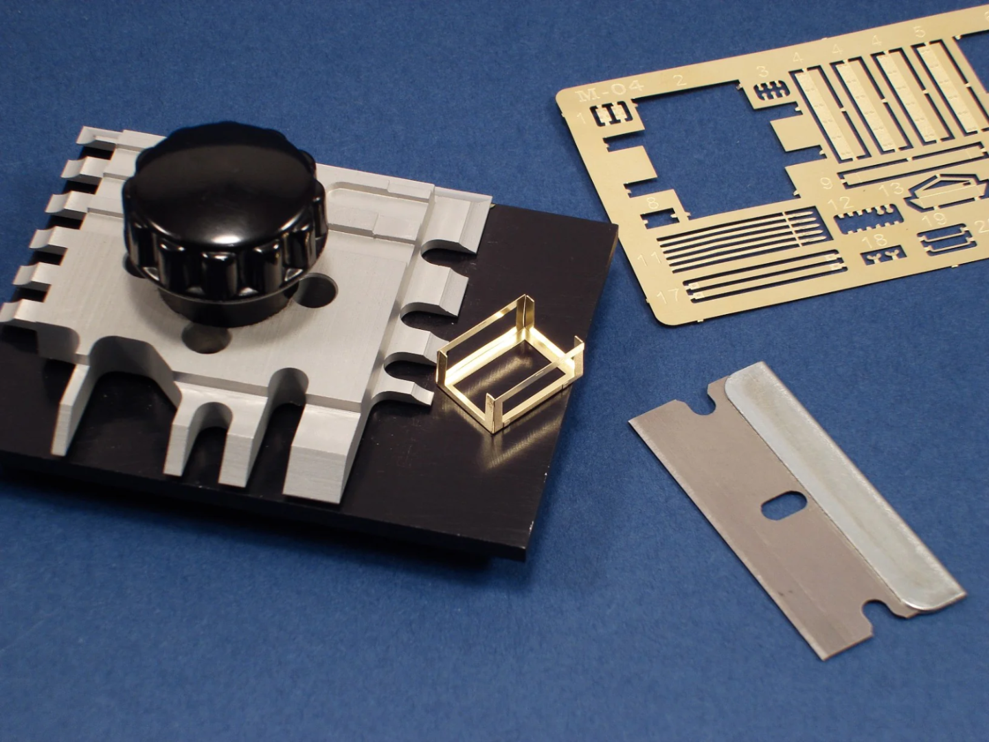
- 973 replies
-
- 5
-

-
-
- gun dispatch vessel
- victoria
- (and 2 more)
-
When one looks closely at the above photograph, it is a bit strange, as it seems to show only one block on the starbord-side. The end the guy holds in his hands is loaded and runs down to the block, thence (presumably to the rail and another block(?) and from there back to the tiller. The second, loose, end the guy holds runs to a block on the rail and then to the tiller, where it is made fast with a knot, it seems. Strange assymetric rigging. Steering with ropes running to a tiller (usually facing back out from the rudder!) or a yoke was very common on Arab vessels around the Indian ocean and also seem to have entered through them into some traditional Spanish boats.
-
HMCSS Victoria 1855 by BANYAN - 1:72
wefalck replied to BANYAN's topic in - Build logs for subjects built 1851 - 1900
Yep, nice metal work!- 973 replies
-
- 4
-
-
- gun dispatch vessel
- victoria
- (and 2 more)
-
Coming on nicely! Didn't we have discussion of the flooring already? I think panels made from individual lengths of planks, tied together with cross-pieces would be an option. These panels should be short enough to be taken out between any eventual benches etc. to allow bailing out the boat.
-
Thanks, Bob, that looks promising. I will have to look into getting one of those ... Regards from the Spanish Mainland.
-
Sealing after coppering?
wefalck replied to BBrueck's topic in Metal Work, Soldering and Metal Fittings
Not sure what you try to do, to put some sort of thick coating onto the copper that kind of covers the edges? Not sure I would want to do that, because it would change the appearance of the crispiness of the edges - otherwise the effect would be neglible. Otherwise, there several threads here that discuss the merits of preventing the copper from oxidising or otherwise. -
The original poster did not mention, what he wanted to use the tweezers for. Some additional information in this respect could lead to more specific answers. There are hundreds of different types of tweezers for different purposes, of different quality and, therefore, price. The watchmaker fraternity, in particular, uses a wide variety of tweezers for specific purposes. As they work with metal, they tend to be harder than the biological/surgical ones. Also dentists' tend to be harder. Another factor is the overall stiffness, which depends on the steel and the thickness of the material. Many reputed manufacturers now seem to sell their 'seconds' (which usually are still good enough for our purposes) through traders to the public. There are specialist traders e.g. on ebay that trade in such medical and biological tools. It may also be useful to check the on-line catalogues of medical and watchmaking supply houses to get an idea of the models available and their specific designations. Use these then to search on ebay etc. Buying tweezer online can be a bit of a hit and miss. Particularly very fine pointed tweezers I would not buy on-line, but would want to check in person their tips and how precisely they close. I bought my main 'working' tweezers in person at a watchmaking supply store some 30+ years ago. At model fairs, flea-markets and such events there are often trade stands that specialise in such 'seconds' medical etc. tools. This gives you an opportunity to check the quality. Keep on the look-out for antique equipment, the steel in them is often much better than in what is flooged new to us modellers. Having said that, those Tamiya bending tweezers I didn't know and they look quite interesting. Do they properly close along the full length of the narrow tips? Finally, if you get one of the cheaper ones for a few €/$/£ you can also grind the tips to your needs. Wouldn't do this with an expensive Dumont one, of course ...
-
Bluenose staysail halliard - confusion
wefalck replied to hamilton's topic in Masting, rigging and sails
I am not an expert on these, but looking at the arrangement and reading the explanatory text, it appears that the idea was to lead each of the halliards to different sides of the boat. In practice only one would be worked, persumably the windward one, as the leeward belaying point might be awash when racing. I think that is the idea, as otherwise there is no mechanical advantage over a single halliard. -
Well, a grand re-opening of the Museum is scheduled for 17 November this year: https://www.musee-marine.fr/nos-musees/paris/expositions-et-evenements/les-evenements/le-vendredi-17-novembre-2023-le-musee-national-de-la-marine-rouvre-ses-portes.html I have seen various projects and sat through various enthusiastic presentations by the director of the museum, but as various museology consultants got their fingers into that pie, it will not be the same as before. First of all, it seems to have mutated from a naval museum to a sort of ocean museum with the usual didactic raised finger. Second, the navy (who is the owner) seems to have succumbed to idea of a visual show, rather than to make the most of their material heritage. It seems that it will not be quite as bad as the NMM in Greenwich, but it will have far less the character of a study collection than it used to have. We'll have to see.
-
Talking about the size of models owned by the Musée de la Marine: the biggest is a fully operational demonstration model of an 18th warship that will be once again shown in the entrance hall. If I am not mistaken, it is around 4 m heigh and 6 m long ... Their ropewalk is actually of an ordinary design, that can do 3 ply and 4 ply ropes of a fixed length. The size of ropes one can do with a machine depends, of course, on the physical strength of it and the maximum weight one can put onto moving end. Conversely, it may be difficult to make very fine, say sub-mm rope with such big ropewalk.
-
The good thing about working on niche subjects is, that forgeries are less likely to occur.
-
I have seen the Museum's rope-walk in their workshops in Dugny (next to the old airport Le Bourget). It is just an ordinary machine, except that they apply the weight to the moving end by a set of multiple pulleys. I gather by chosing how many sheaves they use, they can vary the pulling force.
-
Well, weren't midshipmen not put through almost all mundane shipboard tasks as well so that that they better understand what they will be commanding later?
-
The last photograph seems to show an officer painting a funnel !?
-
I love this old-time steam-technology ... Over here in Europe, of course, we also have narrow-gauge rotary steam-plows. Here is a video from the Bernina Pass of the Rhatian Railway in Switzerland: https://youtu.be/oGndpEPgEgw?feature=shared They keep the line open all year around at least to the Italian border. A couple of James Bond ski pursuits were filmed in the area, particularly on the Morteratsch glacier. I used to ski there, when I was a student.
-
When I have been the last time in New York, around 2000, the tugs still had those D-shaped wheelhouses I seem to remember ...


