


wefalck
-
Posts
6,668 -
Joined
-
Last visited
Content Type
Profiles
Forums
Gallery
Events
Everything posted by wefalck
-
 Is this an optical illusion, or are the frames kind of inclined backward on the first image? I would have thought they would oriented just in the opposite direction, if anything, to be more perpendicular to the outside of the hull (more like cant-frames). This would also reduce the amount of bevel needed - bevel means more wood to cut away, which the shipbuilders would have avoide being wasteful in both, material and labour.
- 174 replies
-
- 4
-

-
- Vigilance
- Sailing Trawler
- (and 1 more)
-
And then there are people without bandsaw, who have to make do with their lathe ...
-
Liver of sulfur (a mixture of different potassium (poly)sulfide) and the commercial blackening agents are two rather different animals chemically. Liver of sulfur forms metal sulfides with the exposed copper (or silver) atoms on the surface of the respective metal. So, it is not something that covers the surface, but a chemical compound intimately attached to the bulk of the metal. Being a sulfide, liver of sulfide solution quickly oxides to sulfate (eventually) and then obviously does not react anymore with the copper. Brass blackening solution typically contain a selenium compound that reacts with the two metals in brass (copper and zink) and forms a solid film on the surface that is chemically bound to it. However, if you let the part for too long in the solution, a rather bulky surface precipitate forms that then scales off quickly. Blackened surfaces must be protected by rubbing them with machine oil (for tools), a drying oil (such as lineseed oil) or varnish. Ziselated surfaces of silver cutlery and other silverware are often enhanced by treating the low parts with liver of sulfur (false 'niello') and these areas stay black in spite of daily washing up. However, modern dishwashing tabs seem to contain oxidising agents and the 'niello' disappears after a few rounds in the dishwasher.
-
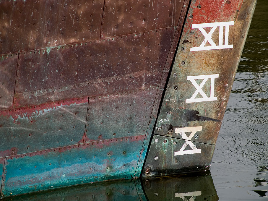
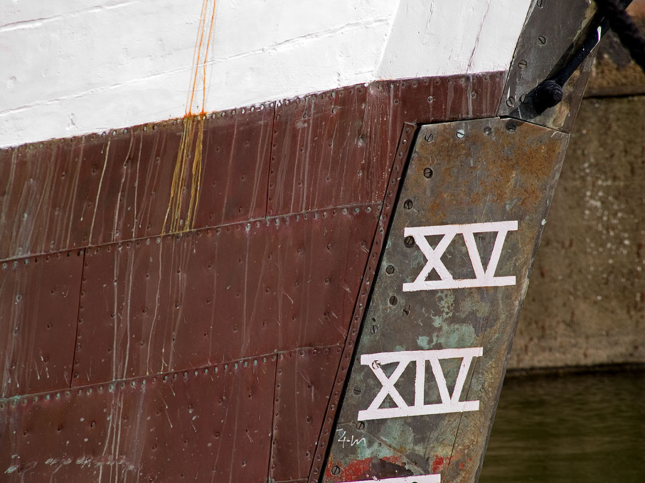
This is how the restorers of HMS GANNET (1878) in Chatham thought it should be done: Their Portuguese colleagues restoring DON FERNANDO II E GLORIA (1843) in Lisbon seem to agree on top-down, but the course along the waterline seems to have been put on last: I don't have shots that show the keel, but there is the possibility, that the plates around the keel were put on before the plating from above arrived. On the other hand, putting on the plating around the keel last also makes sense, because these may be damaged when a ship touches ground and are theneasier to replace. Dito. for the course along the water-line that may be easily damaged by boats coming alongside.
-
Indeed, I have been following the TALLY-HO reconstruction. However, making templates and jigs in 1:1 a lot easier than for fiddly models. Watch- and gun-makers use single-lip or D-bit drills for deep straight holes. Old-time well-builders with tree-trunks also use hollow augers to drill straight holes along the trunks.
-
I am always amazed watching videos of full-time construction how they manage to come out at the right location, when they drill deep holes ... I think in the old days they used augers or 'canon-drills', rather than spiral drills. The former have less tendency to wander.
-
Pulled the Trigger == Lathe coming
wefalck replied to kgstakes's topic in Modeling tools and Workshop Equipment
Most of my (miniature) model work is done with collets, but for larger and in particularly flat parts it is handy to have a three-jaw chuck with stepped (reversible) jaws. Are the jaws on the chuck above 'soft', i.e. can be machined? Otherwise, I would add to the toolkit as (perceived) needs arise, even though that may delay your work temporarily. In this way, you are sure that you have what you need. Roger mentioned a 'test-bar' above - beware they tend to be very expensive and I dare to say, not many people have one, me included ... I don't remember the spindle thread on the Taig, but Sherline offer their chucks (good quality!) with various threads. At some stage Taig offered their lathes with a spindle bored for horological WW-collets, which would have been my choice due to endless variety of spindle-tooling that is available for them. Makes holding of small parts simple and safe. -
Spent last week in Lisbon for business and over the weekend popped into the bookshop of the maritime museum in Bélém (which is not what it used to be ...). Anyway I picked up this book: Simões Dias, F. (2018): As Embarcações Avieiras e outras traditionais do Tejo – Las Embarcaciones Avieiras y otras tradicionales del Tajo.- 237 p., Lisboa (A.I.D.I.A.). A nice book with lots of drawings of different boat types along the Tejo/Tajo/Tagus, but mainly from the Portuguese part. What struck me was the PICARETO from the middle stretches of the Portuguese Tejo, which has a very similar profile with long drawn-out bow and similar plan view as your canoa.
-
I absolutely second that. I made a foray into into inserts and brazed carbide tools, but ruefully returned to my shop-ground HSS-tools, at least for brass work. There is one exception though: I love to use single-lip carbide end-mills as boring bars. These are as keen as HSS and much stiffer. When working with steel, I also like to use a very specific range of brazed carbide tools, those designed for so-called 'Swiss-lathes', these are automatic turning lathes for the mass production of small parts. They are difficult to find at a good price though. Sometimes they pop up on ebay et al. Their shaft measures only 5 mm x 5 mm and they are better ground than the brazed tools for the hobbyists. There is one notable micro-machinist and clockmaker who swears on brazed carbide tools: Jerry Kiefer (he seems to be also a promoter for Sherline ...). Perhaps he has the possibility to grind and hone them really well or access to better quality carbide.
- 128 replies
-
- 3
-
-
- zulu
- sternwheeler
- (and 1 more)
-
Personally, I like to work with steel, but having to remove large amounts of steel on small machines can be tedious. It is not so easy to get good-quality aluminium and Al leaves traces on surfaces due to its oxide layer. If I had to replicate the above tool, I probably would fabricate it from a steel disc and some bar-stock roughened out seperately. The two parts could be made to screw into each other or silvered soldered. That would be followed by the final machining. Anyway, one has to use one's imagination and/or reading books and/or (today) watching YouTube videos to get ideas. When you discover a need, you will soon discover also a solution that you can adapt to the capabilities/capacities of your machine.
-
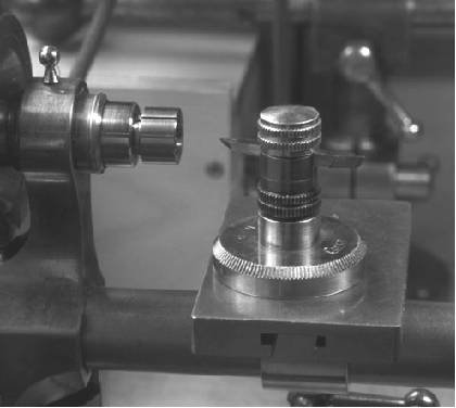
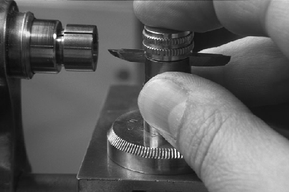
To answer the leading question: everything that is round in cross-section (and a few more things ...). Watchmakers have been using hand-gravers on metal for centuries very much like wood-turners use their chisels. This requires a certain dexterity and practice. Personally, I use it too little to have developed appropriate skills. However, the German lathe manufacturer Lorch, Schmidt & Co. (long defunct) offered a gizmo for less-skilled free-hand turners, which seems to have inspired the above modern tool: The two images are from Tony Griffith's Web-site lathe.co.uk. I gather I don't infringe any copyright here, as this is actually my own thumb on the picture 😁. A small after-market supplier, www.gg-tools.de, offered copies of this graver-holder, but I did not check, whether it is currently available. Otherwise, the beauty of a lathe (and other machine tools) is that you can use it to make more tools and gadgets. So you could make such a graver holder easily from some aluminium stock to fit the centre-height of your lathe. You would also need to attach a thick aluminium plate to the bed of the lathe. One could also add a follower nose to it and clamp a template to the base-plate. I have used this graver-holder to turn flared model parts, for instance, and made a lot of ball-handles for my machines.
-
That guide on the handle is not a bad idea - the pivot on the handle is always a weakness and wears on both, shop-made and industrial gadgets.
-
It might be easier to glue oversized roughend out parts to the boom and then shape them using the boom as a handle. Also leave the parts longer at the jaws end so that can drill a hole first where they open - in this way you can get the hole in line with the boom. Then trim to shape with files and sanding sticks, rather than a knife. Another strategy could be to take a single flat piece and cut a steep V-shaped notch to match the flattened sides of the boom. Glue in the boom and then continue as above.
-
I gather that is how 'shipbuilders' measure the length - between 'perpendiculars' ... Otherwise, one could contact the Lunenburg museum guys. I remember from my visit in 2007 that they were building dories in the workshop there.
-
Pretty neat fire-wood, I would say ...
-
Pulled the Trigger == Lathe coming
wefalck replied to kgstakes's topic in Modeling tools and Workshop Equipment
Neat self-contained unit! Just a couple of observations based on 35+ years of experience using such small lathes: - I think I would have fixed the lathe closer to the front edge, as you want to get really close to the work (wearing safety glasses !), when working on small parts. - I run all my electrical equipment off momentary foot-switches; this allows me to interrupt the current just by lifting the foot - handy during normal operation and absolutely vital in an emergency. -
For the cowls (this is what the ventilators are called) you presumably started from brass discs, I assume? Did you determine the necessary diameter by trial-and-error? One day, I have to get myself one of those dapping blocks (as jewellers call it) and matched punches ... China and India throw them onto the market at reasonable prices.
-
ANCRE.fr
-
Violin by wvdhee (Walter) - 1/1 - from scratch
wefalck replied to wvdhee's topic in Completed non-ship models
And: how does it sound ? -
There are thousands of books, photographs, prints etc. on that site - after all, it is not just a 'site', but the digital portal of the French National Library! Don't look for ship's drawings, these are either with the Service historique de la Defence (SHD) in Vincennes (late 19th century to present) or with the Musée de la Marine in Paris (everything older than late 19th century).
-
I think I would have left the exposed frames bare wood (protected with some sanding filler). Some builders put tar onto the frames for protection, but I am not sure that would have been practice at the Spanish coast. Coming on nicely ...
-
Yep, that's what I meant 👍🏻 These glow-head engines first developed in Denmark and the Netherlands for the fishing industry had to have long-strokes because the poor fuel they were designed to run on needed time to fully combust. Hence the low RPMs of around 50 to 150. They would literally run on any kind of liquid or semi-liquid hydrocarbons, such as rancid butter or seal-oil, though soot was a problem. One needed to start up the engine on something more flammable, such as alcohol or petroleum and then switch to the main fuel. The boats had two tanks for that purpose and sometime an additional tank on top of the engine to make semi-liquid fuels more liquid.
-
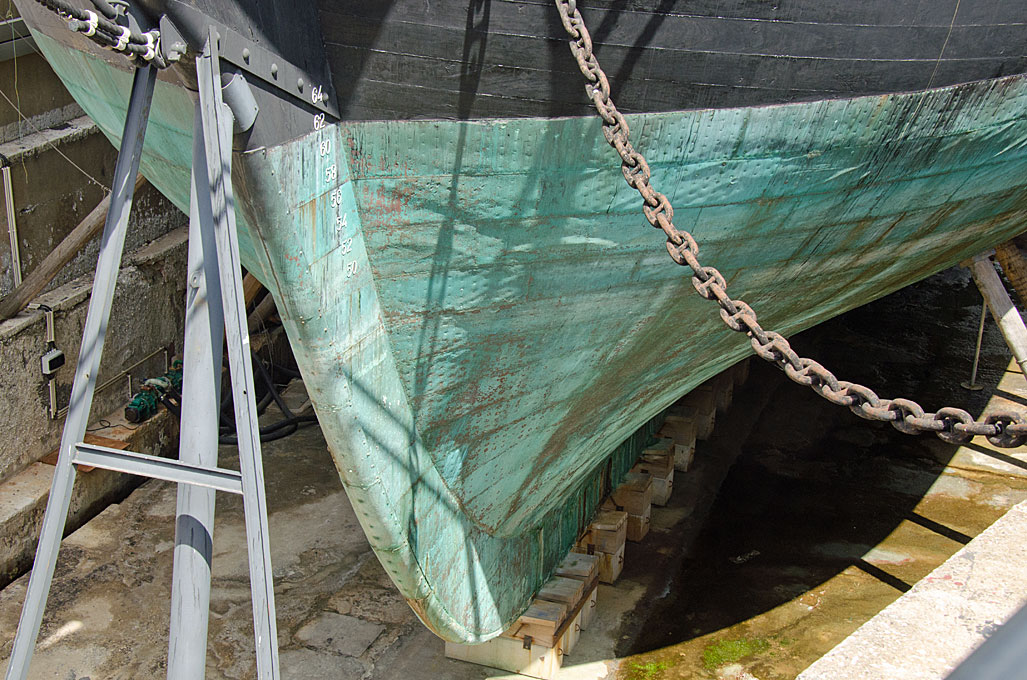
It appears that the pump was driven from the lay-shaft in the foreground of the lower picture. This has chain-wheel for an ordinary chain just inside the spill-head. This chain presumably led to the frame just port of the pumps, where there was a similar chain-wheel on a shaft that seems to drive an excenter, which in turn seems to have driven the balancier of the pumps. However, that balancier and the piston-rods for the pumps are missing. It is not very clear, but I think the cargo winch in front of the pumps was not driven from the lay-shaft, but traditionally via hand-cranks (missing). As I suggested in an earlier post, there was a sliding pinion that engaged the large wheel. In this way you had a two-speed winch: the upper spill-heads are driven directly from the cranks, while the lower spill-heads were driven through the gear-train, resulting in a mechanical advantage. There are two ratchet-wheels on the whinch, one oriented clockwise and the other anti-clockwise, so that one could use the winch in both directions. This kind of winch was universal on small cargo-vessels from the early decades of the 19th century on.
-
Well, the awns are there to grip animal furs or bird feather to help the seeds spreading ... I think some plumber's hemp, brushed straight, might be a more promishing option. I suppose you would get this in a DIY store (at least over here in Europe this is not a problem). The ridges of thatched roofs are their weak points and special techniques were develped in different cultures to overcome this. In some place pieces of turf were arranged along the ridges, fastened with wooden spikes, and grass and moss encouraged to grow there; in other places they used wooden boards, tiles, or in later years sheet-metal. On a boat, I could imagine that a piece of sail-cloth or similar could have been tied over the ridge. It would add to its improvised look 😉


