


wefalck
-
Posts
6,644 -
Joined
-
Last visited
Content Type
Profiles
Forums
Gallery
Events
Everything posted by wefalck
-
 Thank you very much gentlemen for your kind words 😇 McNarry was far more productive and worked on much smaller scales (I think in 1:384 = 32 ft to the inch mainly), so I am far away from challenging him ... Pat, I am currently working on editing a number of manuscripts that will eventually form a book on the ships' boats of the Prussian and then Imperial German Navy 1852-1918 to be published by our society. Some of our members have carried archival etc. research for several decades. One of whom, for instance, focused on two series of Crimean-type steam-gunboats that were built between 1859 and 1865 and unearthed various inventories, including detailed their boat inventories. According to those the hoisting strops could be either rope or chain. The main point of attachment was a ring-bolt through the keel, just abaft and before the aprons of the stem- and stern-posts respectively. However, if you were to hook the tackle directly into those rings, you would suspend the boat from underneath its centre of gravity and it would fall over. To raise the points of suspension to around the level of the gunwale, a strop is rigged and is steadied with a more or less horizontal strop that attaches to a ring in the stem- and stern-posts respectively. Likewise, from the ring were the two strops meet, stays extend to the sides of the boat, to prevent it from leaning over. As far as we know, this arrangement persisted since the 1850s, but chains replaced ropes. It is quite likely, that it was at the same on RN, as in fact the early boats on some German ships for which also have inventories were RN boats - the ships were purchased second hand from the RN. The Prussian navy put these boats through trials in order to assess them and develop design criteria for standardised German-built boats. The reports on these trials have survived in the archives. Incidentally, the Prussian navy also undertook in 1860 experiments with Clifford's release gear for boats, but so far it is not clear, whether it was actually adopted, but I don't think it was, as it is not mentioned in later textbooks on the Imperial Navy's boats. Keith, the laser-cut parts for the oars are really flooded with the varnish on a sheet of glass and cautiously aligned until dry. The paper then is quite stiff. I smooth it then a bit with a diamond nail-file, but that is difficult with such flimsy parts as the oars. Adding more lacquer and then paint will smooth out the whole thing. Did this answer your question?
 -
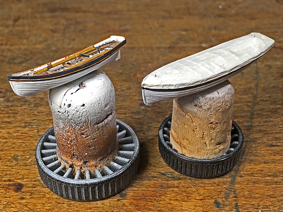
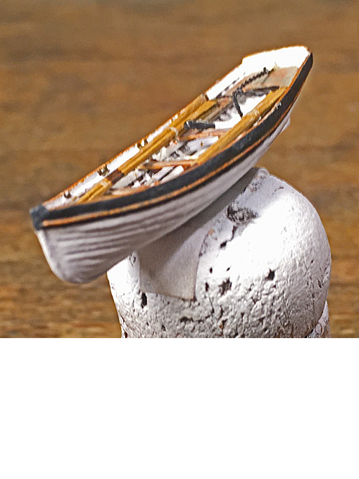
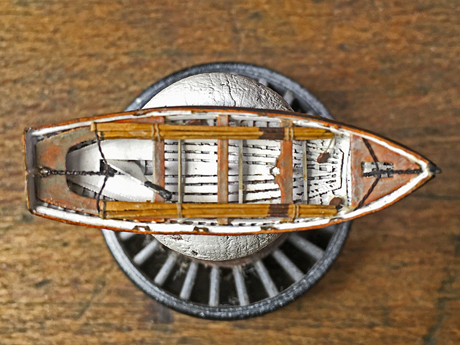
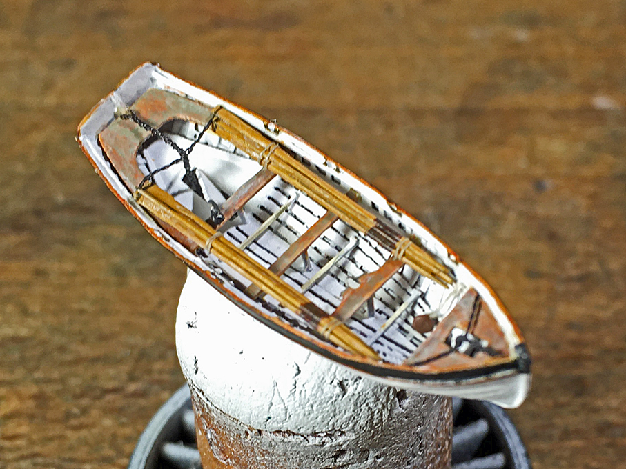
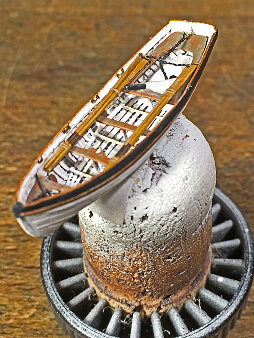
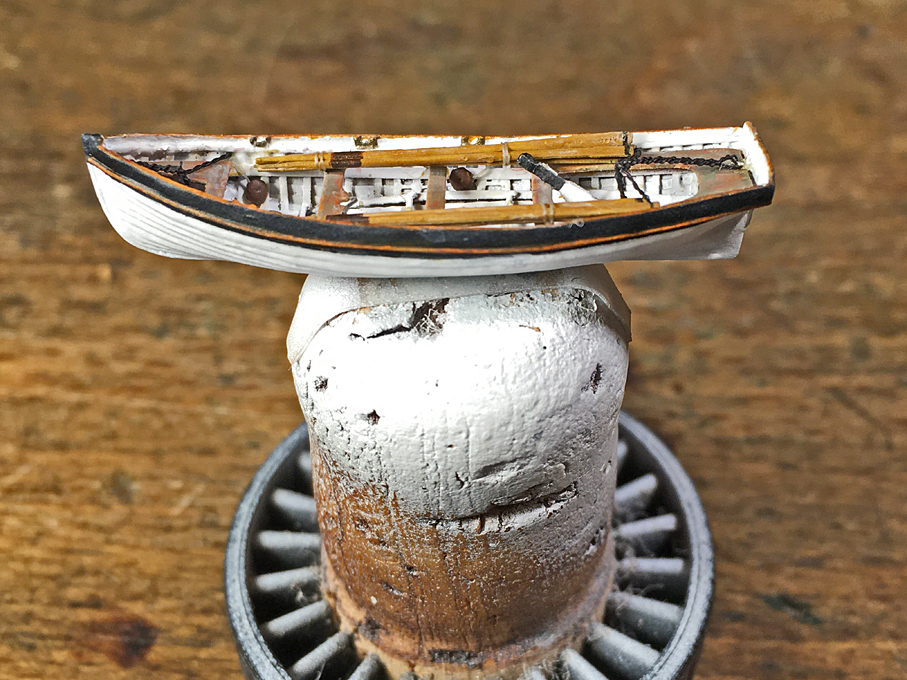
Thank you to all for your kind words ! ************************************** Completion of the Boats Sorry for the long hiatus, but again real life with various obligations and diversions got in the way. Also, there has been a lot of correction work and making small details that are not a lot to show, but take time. I adjusted the colour of the seats etc. somewhat and also worked on the rubbing strakes. For this I got myself a couple of markers with acrylic pigment paint (Faber-Castell Pitt Artist Pens with fine hard tip and soft brush-like tips) in various ‘wood’ colours, which really turned out to be useful for touching up etc. Then I turned my attention to the oars and with a bit of trial and error managed to produce relatively reasonable laser-cut parts. Each oar is lacquered together from three layers to simulate the shaping. The round was build up with more varnish and they were finally painted in wood colour and the iron band around the blade simulated with my 0.1 mm marker pen. Not sure, whether they should be black though, as the original specification called for copper bands. There are a lot of unknown details. I know from the sources that the oars should be stowed ready for use in order of the benches, the outer pair for the first bench in the bow and so on. However, I don’t know how they would have been secured for the sea, probably with a rope around the benches. However, laying out the oars like that would have meant that there would have been no space for the men to step into the boat when lowered. So, I arranged them in bunches alongside. I also realised that I forgot the spur for the heel of the mast, so this was added. While arranging for the hoisting chains on the covered boats was easy, here it is a rather flimsy affair and I am not sure that it will work, as they are only glued. Likewise, the stays. The chains were simulated by drilling together two 0.2 mm wires until the pitch was about (without measuring) the length of a ring in the chain. Two of those drilled-together wires were drilled together. The overall appearance is roughly like a twisted chain. Boats need rudders, so I drew one and cut it from Canson-paper in the usual way. When hoisted, the rudders are unshipped and stowed in the boat. However, I don’t really know where and how. Stowage of various items is another uncertain point. There are a lot of items in the surviving inventories, such as an anchor, a small water-cask, a compass and a boat-hook, but I do not know how and where they were stowed. So I will omit them from the already quite crowded looking jolly-boat. The only thing I made were four fenders that are hung inside the boat. With this the jolly-boat is complete. In parallel I worked on the second cutter that also will be shown covered. As this is the same process as for the other covered boats, I do not show the process again. Just a couple of shots of the collection of finished boats. To be continued ....

- 935 replies
-
- 25
-

-

-
So it can use G-Code? Somehow I had the impression that the driver that comes with it is made for bit-images.
-
Split ring making process
wefalck replied to Dave_E's topic in Metal Work, Soldering and Metal Fittings
Well, soldering is a basic skill any shipmodeller should attempt to acquire (not that I am real master of it myself ...) and I owned a soldering iron since my early teens. They cost just a few euros/pounds/dollars/yens/etc., so there is not big hurdle to take for some basic equipment. -
Just read on their Web-site. It feeds indeed a nozzle coaxial to the laser-beam to blow out burnt material, so that it does not obstruct and scatter the laser, thus making the cut narrower with less charring (my interpretation, not their sales-pitch ...). However, if I read correctly, it works from bit-images, not from vector graphics. I wonder, how well it would be doing on lines oblique to axes of the machine and on curves.
-
US 6” gun by RGL - FINISHED - Panzer Concepts
wefalck replied to RGL's topic in Non-ship/categorised builds
Heavy and siege artillery pieces were usually broken down into several loads, as not only towing-capacity was limited before the around the mid-1930s, but also the load-bearing capacity of roads and bridges, not talking about moving them across fields. The Austrians had a 38 cm siege howitzer designed in 1916, which was broken down into four loads: Barrel 38 t, carriage 33 t, and two lower carriage/foundation trucks of around 37 t each. It took 8 to 20 hours to prepare the foundation in soft ground and several days on rock. Assembly of the gun took 6 to 8 hours. One of them is preserved in the Army Museum (Heeresgeschichtliche Museum) in Vienna. If I remember correctly, they used a diesel-electric tractor to have enough torque on the wheels.- 235 replies
-
- 11
-
-
Split ring making process
wefalck replied to Dave_E's topic in Metal Work, Soldering and Metal Fittings
Jewellers (silver-)solder rings on a cone-shaped carbon-rod. While, it is not carbon, but graphite mixed with clay, one could perhaps use a lead-pencil mine as mandrel for soldering. They come in various diameters or one could just sharpen an ordinary pencil and put this into a vice for soldering. Solder paste would be the way to go. I am wrapping (soft) wire around a drill shaft, pull it off and then cut the rings with a scalpel on a glass plate. In this way the kerf is on the inside of the ring, where it is less visible even when not soldered. In this way I can produce rings with 0.3 mm inside diameter, if needed. -
What laser-cutter do you actually have?
-
What always puzzles me is, how utterly impractical from both, the handling and the maintenance perspectives these ships must have been - dressed to impress ...
- 2,699 replies
-
- 5
-
-
- heller
- soleil royal
- (and 9 more)
-
I wonder sometimes what is more difficult, to build a model or the real ship/boat? Measuring parts should be easier on the smaller parts than on several metres long pieces of the real thing. But then accessibility and measurement tolerances are an issue in models. Well, 18 to 20°C would be far below my comfort zone ... at least for working sitting down.
-
Nice, clean turning! Steel?
-
When I read this correctly, then only plans for 'ground trainers' are offered, which I would interpret as non-flying - would reduce the risk considerably. I am not into flying, but seem to remember having read that in the 1930s and even into the 1950s glider enthusiast build their own gliders - the Wasserkuppe mountain in Germany was one of the centres for glider flying at the time. And you can see various videos on YouTube etc. where people built oversized 'drones' and fly with them (of course they are not drone anymore then ...). Due to tight airspace-regulations and a lack of free space this seems to happen more in remote areas and not in Europe.
-
Well, failing that, we would be content with some progress report on his railway adventures ...
-
Looking very nice, well done 👍 One thing that puzzles me, however, is the orientation of the saw-blade versus the rollers. I would have expected that the rollers feed (planks) into the saw-blade ... And a little technical detail: the ends of leather drive-belts were attached with special metal 'agraffes' and they don't overlap. If they did overlap there is a jump and slip on the pulleys. Sorry to say, but I am bit disappointed over technological progress - a boring electric motor and not a little horizontal steam-engine, the boiler of which is fed with saw-dust and off-cuts
-
Acrylic paints are complex emulsions with either water, or alcohol or a mixture of both as solvents. They may also contain surfactants as emulsifiers. Emulsions are very delicate things and can easily break down when using the wrong solvents, resulting in curdling with resulting clogging of the airbrush for instance. In such cases they also do not form the cross-linked network of acrylic molecules that form the paint layer. It appears that Vallejo uses a relatively simple system that can be diluted with water, dito. for the German Schmincke paints. I do not have experience with products of other manufacturers.
-
If the intended purpose doesn't work out, you can always turn it into some workshop diorama - thinking about lathes, milling machines, overhead line-shafts and such things ...
-
How will the saw be driven? Seems to call for a horizontal steam-engine ... I love this project. These wooden buildings have a lot of character!
- 333 replies
-
- 12
-
-
Aren't you afraid that adding the stays later might pull (ever so slightly) the shrouds out of alignment and, hence, also the ratlines?
-
That's quite a high-tech stand ! ... somehow it reminded me of those eerie-looking outside braces doctors use to align broken legs ... Perhaps the camera is challenged with the illumination and contrasts, but I found that the underwater body doesn't quite stand-off from the mounting board. It seems to make it difficult to appreciate it's wonderful lines and the artful planking job.
-
I am wondering, musing about the physics involved, how the recoil would be distributed ... part of it obviously would act backwards (depending on the type of locking mechanism) and part of it sideways ...
-
The question is also of what period we are talking. CUTTY SARK for instance has a release gear fitted, which allows to safely let go the chain without using a sledgehammer. This kind of release gear, where the chain is hooked up to a rotating bar with thumbs sticking up, was used until stockless anchors came into use that pull up into the hawse-pipe. The bar has a lever at one end that is rotated by hand to lower the 'thumbs', thus relasing the chains.
-
I can't work when my blood-sugar levels are down and I am hungry ... hands are shaky and I can't focus mentally ... Nice shipwrighting btw.
-
Concerning the submachine gun that fired around the corner: it is a German MP40 and apparently this kind of barrel extension was actually experimented with for urban warfare during WW2. Today, with video-cameras, GPS etc. for aiming it might work ...
-
Or, perhaps we are the intelligent ones that survived ... 😇 Considering the 'fully comprehensive insurance'-attitude of modern attitude, the future development of our gene-pool is quite worrying 🤔
