bhermann
-
Posts
549 -
Joined
-
Last visited
Content Type
Profiles
Forums
Gallery
Events
Everything posted by bhermann
-
Jan My limited experience with decals suggests the colors come out truest if they are applied to a white background. In this case I am picturing painting the entire area under the transom white, then making a decal that covers the entire rectangle, with the background blue color printed on the decal. That might make the figures appear the way you want them to. I have read about (but never done) people printing their patterns on paper and then gluing the paper to the hull. Just a couple of thoughts - I look forward to seeing what you come up with - although I think that what you have already looks very nice!. I love the boot at the top of the rudder. Bob
-
Don - I am sorry to hear of the loss of your friend. Cancer can be such an insidious disease. My thoughts and prayers are with you and with your friend's family. Bob
-
Thanks, Rich. A lot of detail was lost in the crash, so feel free to ask about anything. It may help bring back some thoughts from before. Bob
-
Kimberly Two different colors of thread on the models because there are two different kinds of rigging. "Standing" rigging is used to do things like hold the masts in place. Since the masts don't generally move once they are set up, the ropes that holds them in place was "painted" with a tar-like mixture to help preserve them from the elements. Water and salt can do quite a number on rope. "Running" rigging is used to move the sails to take advantage of the direction the wind is blowing from. Since this rope has to be able to move, it wasn't treated with the preservative (which would gum up the blocks and make a general mess) so this rope appears in its natural color on the ship. Hope this helps, and a belated welcome to MSW. Bob
-
Jay - Thanks for adding the section on how you do the model coils. Very clear and very helpful. Now i just need to find the Bos'n and see how large he makes his coils Thanks, Bob
-
Ken - different period, different type of ship, the reef lines on my Bluenose plan measure 5/8", which scales up to 40" at 1/64 scale. The important thing is they need to be long enough to tie together under the boom while taking into account the amount of the foot of the sail that is bundled up on the boom as well as the boom itself. It'll be interesting to see what people come back with on this. Bob
-
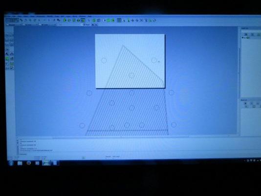
Russ - you bring a smile to my face. Of course I could have traced the sails, but that would have required me to think about it Now that I'm done slapping myself in the forehead, let me try to justify. Let's see, by doing the drawings I'll be able to share my work with any of the thousands of people who are out there build the exact same model I am, and in the same scale?... No, that won't do it..., that would be two people in the known universe. I have a high tech job, and my mind is just wired for using technology whenever possible? Nah, I'm still writing checks every month and sending them to the utility company instead of paying on-line... The sails on the plan show the finished size and don't include the extra needed for the tabling and if I hadn't done it this way I'd have had the devil of a time getting the tabling lines drawn parallel to the edges given my weak drafting skills? Yeah, I'll go with this one. After all I'm the guy who couldn't recreate a triangle by measuring it and letting the computer handle the drawing! OK - now that that's settled, Russ, please continue your efforts to show me the better way. I can hardly wait to hear what the admiral has to say about this one! Simpler is often better, just not obvious to some of us. And by the way, if anyone would like the drawings once I have them all done, just send me a PM and I'll be happy to share. For those of you who remember MSW 1.0, I did something similar with a spreadsheet that documented all eyebolts located on the stanchions and rails that several people got a copy of and found useful. I am willing to share anything I draw up along the way. One future example will be a spreadsheet of all the lines I have rigged. This one has been started and so far has only the bowsprit lines documented (since that's all I've rigged up to now). Thanks, Bob
-
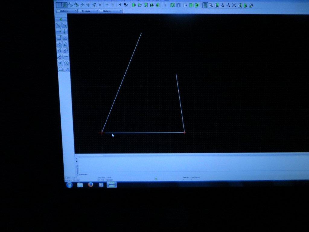
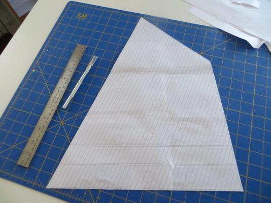
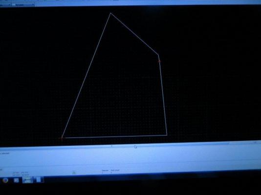
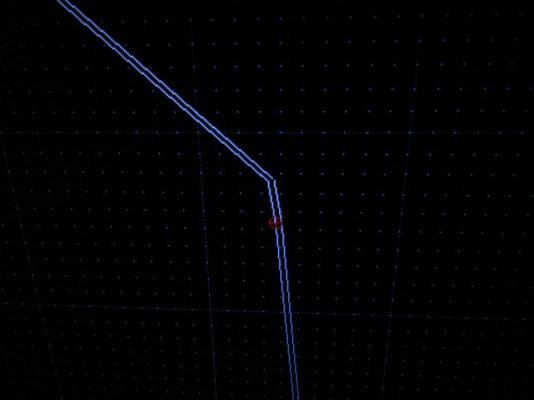
I went ahead and started drawing up some of the jibs. The jumbo jib turned out just fine, but when it came to the larger jib itself, I was not able to get the three sides to intersect properly using the measurements from the sail plan. I kept winding up with a small gap at the head end of the sail. No matter how many times I measured the lengths and angle I could not get the triangle to close. I assumed the issue was with the angle measurements so I decided to change my process a little. I know that if the lengths of the three sides of a triangle are known, the angles can be calculated using some trig functions, so I decided to do up my own little calculation spreadsheet to get the angles based on the lengths I measured. Before getting started, it occurred to me that this big old Internet was out there and I should check because someone has probably already done it. Sure enough a quick Google search gave me several pages to choose from. The ostermiller.org site had just what I was looking for at http://ostermiller.org/calc/triangle.html. I plugged in my three lengths and the page quickly gave me what I was looking for. I was then able to drop the lengths and angles into LibreCad to get the sail outline, draw in tabling and stitch lines as shown in previous posts, and generate the sail pattern. Remaining to do are the balloon jib, the fishermans sail, and the two topsails. After that I will take one of my templates and see how it works on cloth. Bob
-
Jay - That matches how I was taught to do it on my Windjammer cruise a few years ago except when doing the "X"s over the pin, they had us do three instead of four, and the third one was flipped over to lock the line in place instead of pulling it under a previous wrap. Thanks for posting the video and your adaptation for modeling.
-
Rusty - this some very nice work. I'm glad to see you keeping busy. About getting that hole to come out round, I imagine it would be easier if you could do the rounding before attaching the planks to the underlying deck - I'm just not sure how that would be done. I'm curious that the second layer seams line up with the lower layer. I'd think that offsetting them a bit would add strength to the structure. Sometimes I wonder why they did things the way they did. Enjoy your trip - that can be a lot of fun with the grandkids along. If the food and wine festival is still going on at Epoct, avoid that park on the weekends. Lots of locals show up to "drink around the world" and it can get ugly - Walt would be rolling over in his grave. Bob
-
Floyd - I look at those photos and just shudder. It brings back memories of the amount of edge bending that went into my current hull. It seems like there is no way to make it right without spiling a plank that starts out 4 times wider than what you are working with. That plank would wind up looking a bit like a whale - very narrow at the ends and much too wide in the center. I tried picturing how the shipwrights would deal with this on the real thing, and a bit of a light bulb went off. They wouldn't be dealing with a single plank running the length of the hull from stem to stern - they would be using multiple planks in each strake and would be able to change the angle on each plank in the run as partial compensation for the edge bending we need to do to complete a strake with a single piece of wood. I guess that's one more reason for considering scale length planks for our builds ( have to remember that for my next one ). I agree that spiling is the way to go and look forward to seeing your progress on Harvey. I know my observation here isn't particularly useful, I am just suggesting another way to look at the process. Bob
-
Desert_Sailor That's the way I was taught to coil the halliards on the schooner I sailed on. Thanks for a straightforward approach to getting it done on a model. Bob
-
In my case, I believe I picked up 2 1/8x1/8X36" pieces (balsa, that's what they had) at my LHS - the 1/16 x 1/8 was kit stock. It was 6 years ago so my memory may be a bit fuzzy About running out of wood, my kit was short on the number of 1/8 x 1/16 strips supplied. It contained 64 instead of the 70 in the parts list, but I didn't run out of that size (or any other up to this point). These are details that were lost with MSW1, but that is my best recollection. The only kit-supplied part I have tossed was one of the mast dowels. It was just too warped for use. I bought a replacement at Home Depot for that piece. Bob
-
Thanks for the warning, Dave. I will stick with sails for now - should keep me out of trouble. Bob
-
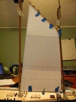
Floyd - in this case I am working under the assumption that what is provided in the plans IS a 2D sail template. In short, my CAD drawings don't take this into account, they assume that a bunch of flat strips of cloth were sewn together to make a bigger flat sheet. I will shape the finished product into wind-filled sails after cutting them out and adding details. I don't know how I'll do that just yet, but there are lots of interesting approaches to be found on MSW. Pete - thanks for stopping by and for the kind words. I love the quote in your signature. As promised, I temporarily attached the the main and fore sails to check for rough fit and to get a feel for where I might be headed with them. Here are the photos. Thanks, Bob
-
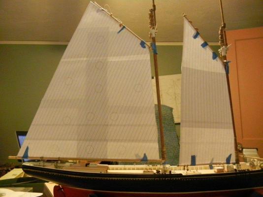
Hi Elia - thanks for stopping by. It IS a rather large sail, isn't it. I have done up the foresail as well and done a very rough attachment to the model. I'll post a picture tomorrow if I get a chance. Once I figured my ay around in LibreCAD, I was very happy with the functionality. Of course I am only using it in a 2D fashion so I can't say how useful it might be in a frame building or lofting scenario. f I ever get to that stage, I'll be looking for recommendations from the more experienced modelers here. It does have exactly the toolset I was looking for to make sails. I will continue to use it as is for the time being and if something simple 3D comes up down the line that I'd like to expand how I use it, I'll certainly give it a shot. I guess I should draw up a template for something simpler, one of the jibs perhaps, and use that to start seeing how this all translates into cutting and making a sail out of cloth. Thanks, Bob
-
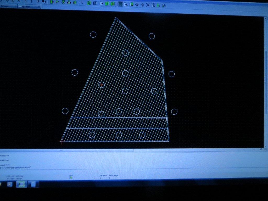
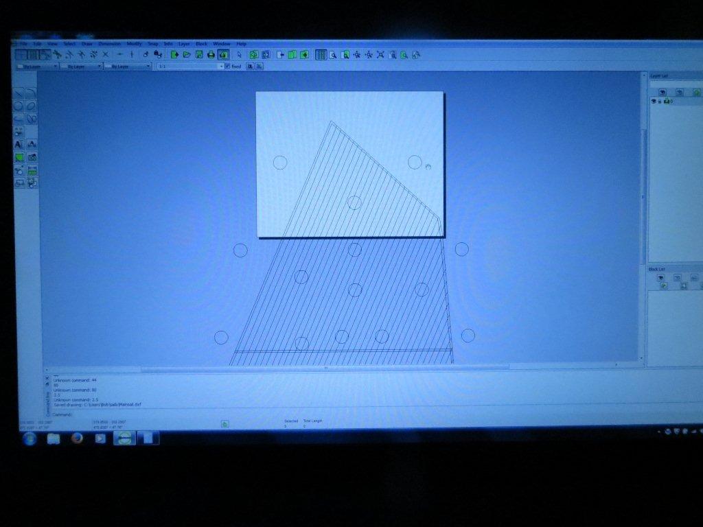
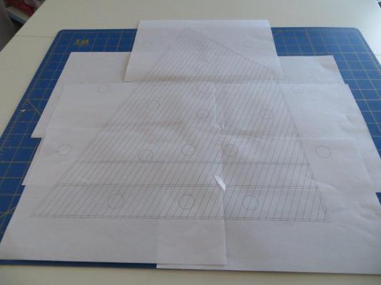
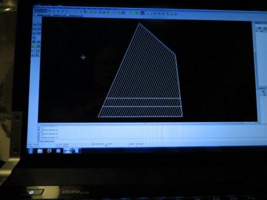
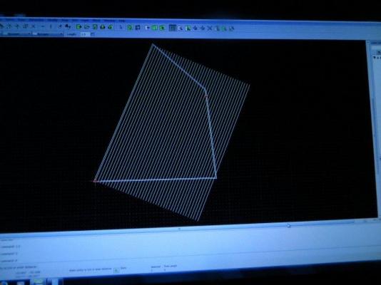
...Continuation After all the seam lines are trimmed, this is the result. The parallel function is used one more time to draw in the reef bands, parallel to the foot of the sail; once placed they too are trimmed. Since this sail is going to be larger than my letter-size paper, I then set up a series of circles to use as registration marks when putting the printed sail pieces together. I may have gone a bit overboard, but I wanted to makes user I had two circles available when lining up any two pages. The programs print function allows you to position which portion of the sail will wind up on the printed page. I wound up with 5 pages for the mainsail and assembled them using the registration marks, then taped them together. After trimming along the edges this is the end result. Any questions/comments are appreciated. Thanks, Bob

-
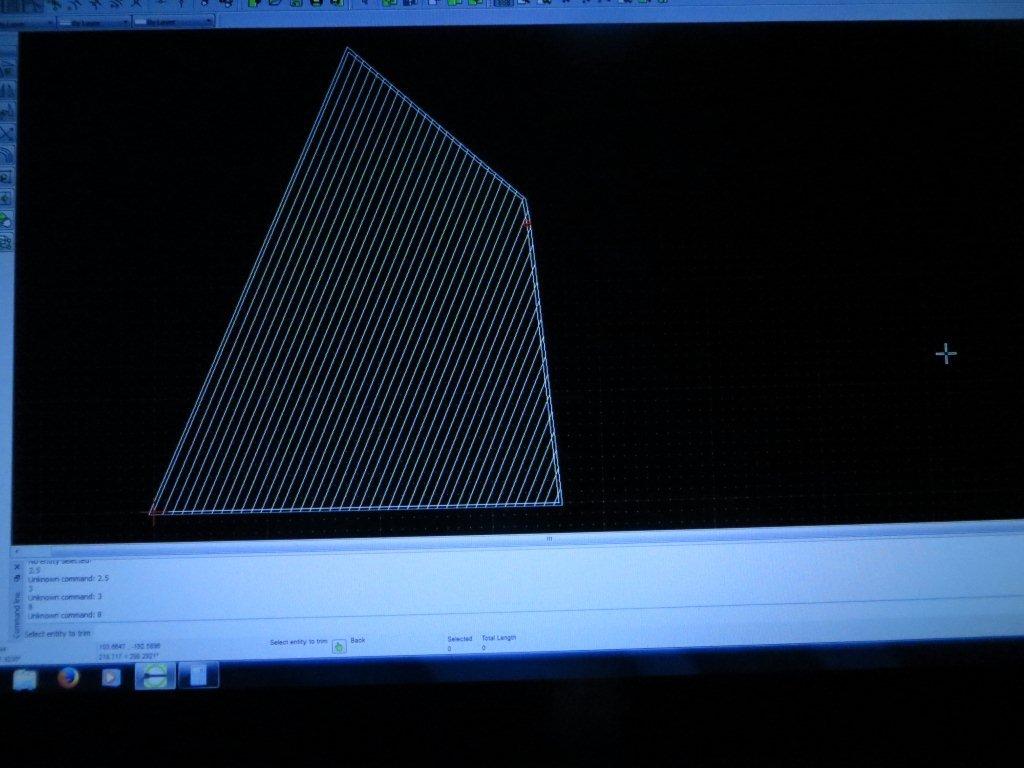
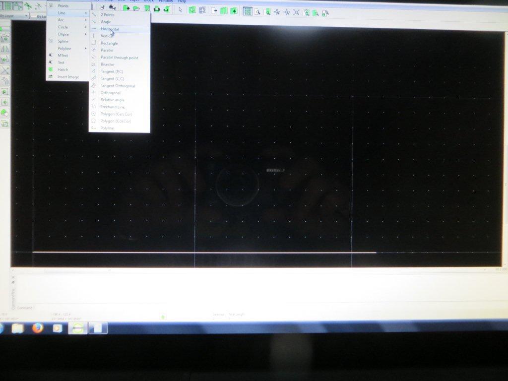
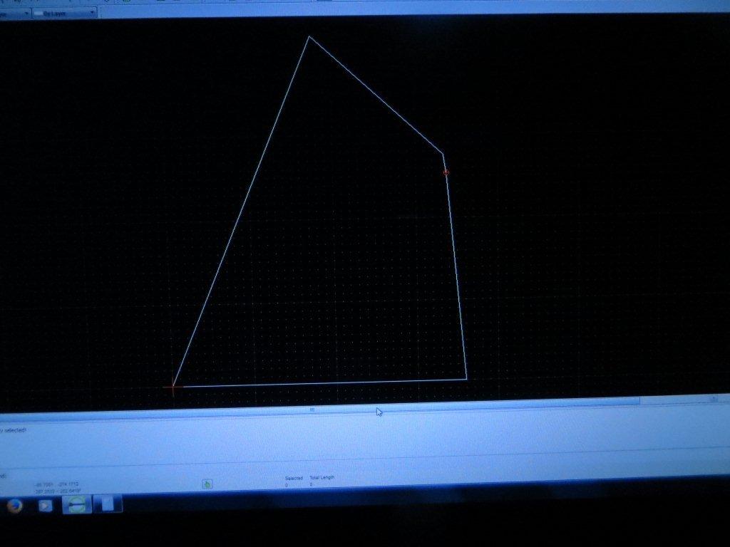
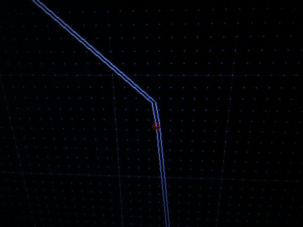
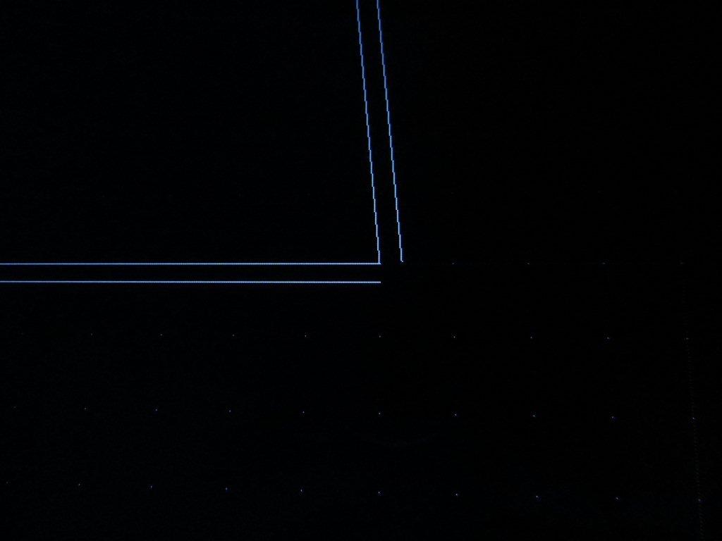
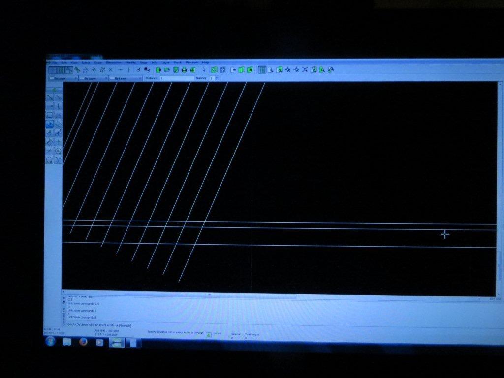
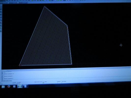
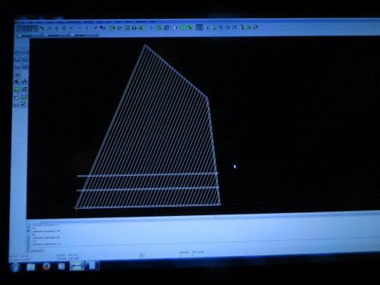
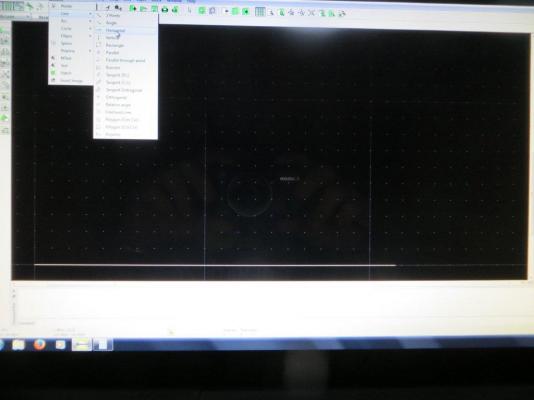
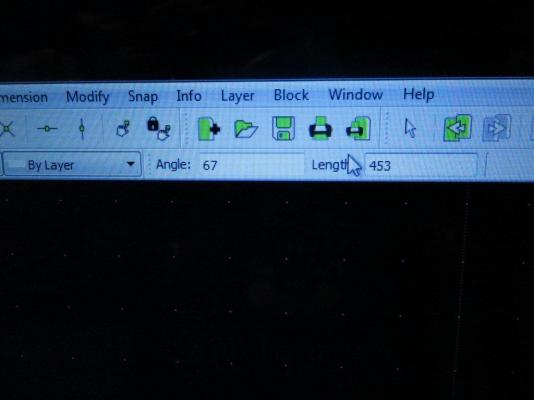
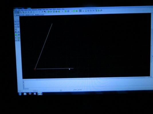
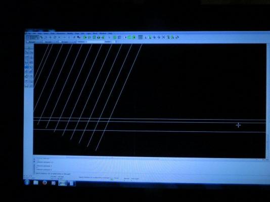
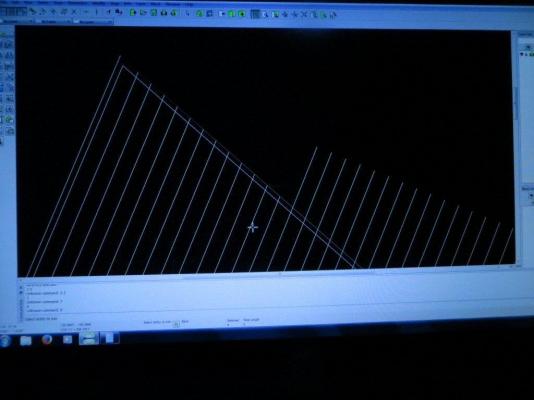
I was not pleased with my attempts to draft sail templates by hand and didn't relish the need to do it 8 times, so I went looking for a CAD program to do it for me. I chose LibreCAD, a free download. This entry and the next will document the process I used to draw the main sail. Most of the LibreCAD functions I used were found in the line drawing menu of LibreCAD, which is shown in the first photo. Up first - draw a horizontal line to draw the foot of the sail. The "horizontal" function allows input of the length of the line to be drawn - and here it is: The "angle" function is then used to add the leech line. The angle from the foot and the length of the leech are input, then it's a matter of clicking the aft end of the foot to place the line. The angle function is used again to draw in the luff line. Then the head is drawn at an angle from the leech. This leave a small gap that is closed using the point to point function to represent the piece of the luff that that deflects away from the mast just below the gaff. The "Parallel" function is then used to draw the lines for the sail tabling external to the existing sails. That function allows you to specify the distance between the base line and the new line, then the mouse is used to select the side the parallel line will be drawn on. There is a function to extend the tabling lines so they form a nice corner (not shown in the next photo). The parallel function is then used to place the seam lines for the sail panels. the plan calls for them to be parallel to the leech. After all the parallels are drawn, it looks like this. Then the trim function is used to clean up the line ends. That function allows you to identify which line will be used to mark the end of the seam line, then click on the seam line to trim the seam. This photo shows the process in operation. The next post will show the remainder of the process and the result. Thanks, Bob


-
The Hunt practicum was very useful to me as a first time builder for getting the hull and deck planked. I think I also used the method there for building the transom. I started moving away from it when it cam to deck furniture and the painting scheme. I think Mr. Hunt misinterpreted the plans when it came to how the rails and upper sides of the hull were colored. As Floyd said, if I'd been aware of MSW at the time, I might not have purchased the practicum at all, but having a detailed plan for planking the specific model I was building was a BIG help. I didn't consider tree-nails or scale length planks at the time, I don't know that I would do one without the other. It looks like you have a nicely shaped hull going. Great job on that! Bob
-
Sweet, John! Great details - I will be taking a real close look at the coils on the belaying pins when I get to a real screen tomorrow. Can't wait for the next one. Bob
-
That's a nice looking set of templates, Jack! Bob
-
Ropewalk Scale Rope Making Tool by ME - opinions?
bhermann replied to rtropp's topic in Modeling tools and Workshop Equipment
I bought one a while back - it is still sitting in the box unassembled. I don't know when I would ever find the time to do rope, I have enough trouble finding time to work on my build! Bob -
Thanks for asking the question, Fred, and to Dave for looking up the photo. I see another thing to be built in my future Bob
-
Jack - in a perfect world I would attach the sails to the mast hoops before locking the hoops in place on the mast. In my case, that realization came too late. I already have the hoops in place between the boom rest and the trestle tree, so I will be attaching the sails to the mast hoops before stepping the mast, but later than I would if I still had accessibility to the hoops. It may not be too late for the top masts, though. I haven't glued the fids in yet, so if I can sneak the top mast past the bails, I may still be able to get the topmast hoops on the sails before locking the hoops in place on the mast. Bob
-
Jack - for the foresail, the mainsail and the topmast sails (in short, everything that ties to the mast hoops), I agree that earlier in the process is better. I am in the process of making the sails at this point, so can't speak from experience, it just feels right. Lacing the sails to the mast hoops feels like the most difficult part of the process. If it could be done off the model, great. If not, it may be a bit finicky working inside the shrouds. I'm not sure I see as much of a need for early on the various staysails. At one time I thought about adding the hanks and getting the sails on the stays before attaching the stays, but as this is my first build it feels like an extra complication that would make setting up the stays that much more difficult. In any case, I would definitely attach the "mast" sails before doing the ratlines, and if possible, before stepping the masts in place. Bob