bhermann
-
Posts
549 -
Joined
-
Last visited
Content Type
Profiles
Forums
Gallery
Events
Everything posted by bhermann
-
Jan-Willem I am using kit-supplied blocks and deadeyes on this build. The lower deadeyes on the channel are round and there are 20 1/8" and 6 3/32" round deadeyes supplied. This includes 4 extra of the large size and 2 extra of the small. The upper deadeyes for each of these pairs isn't round at all, but more triangular in shape, with the point facing down. They come on the laser cut part sheets. The rigging plans don't have any deadeyes at the topmast at all. There is a lanyard that runs between an eyebolt on the cross-tree and an eye spliced in the end of the topmast shroud. I wish I had installed the chainplates before painting. I also noticed a bit too late that the chainplates are actually let into the hull planking to the point where they are almost flush. There may be some photos in the log of the L A Dunton that I took at Mystic Seaport a couple of years back that show very similar details on that ship. (Or they may have been in my more extensive log on MSW1.) If you want to attempt that detail, I wish you well. I was afraid I would cut all the way through the planking if I tried it on my build. The kit supplied blocks are: 5 3/32" single 35 1/8" single 15 5/32" single 12 3/16" single 20 1/4" single 35 1/8" double 15 5/32" double 6 3/16" double 6 1/4" double 6 9/32" triple The MS kit is 1:64 scale so the smallest single block scales to 6" and the largest to 18". The larger sizes are used to control the booms and gaffs, so are used in rigging the main sheets and the throat and peak halliards. The smaller sizes are used to rig the various jibs, topsails, and fisherman sails. If you are not going to set up sails on your model you will not need as many of these. BTW, I'll leave it to you to do the imperial to metric conversion for the various blocks and deadeyes . If I had it to do over again, I would probably replace the kit blocks with Chucks product. I have bought some of his rigging rope and like the look and feel of it. I can't say how well it works just yet, as I haven't had the chance to take it out for a trial yet. The bowsprit rigging was done a long time ago using the kit-supplied line. If you have specific questions please let me know. I am no expert on rigging, but I've been looking at these drawings for a few years so havesome familiarity with it. Thanks, Bob
-
Jan-Willem I'm glad you were able to find a photo of the area - it is nice to get answers to these questions. I agree with the approach. If you can't see separate pieces on the original, it doesn't make sense to model them at 1/64 scale! Bob
-
Congratulations Dave on finishing another build. I love the details on deck and the overall shape of the ship. Looking forward to the next one! Bob
-
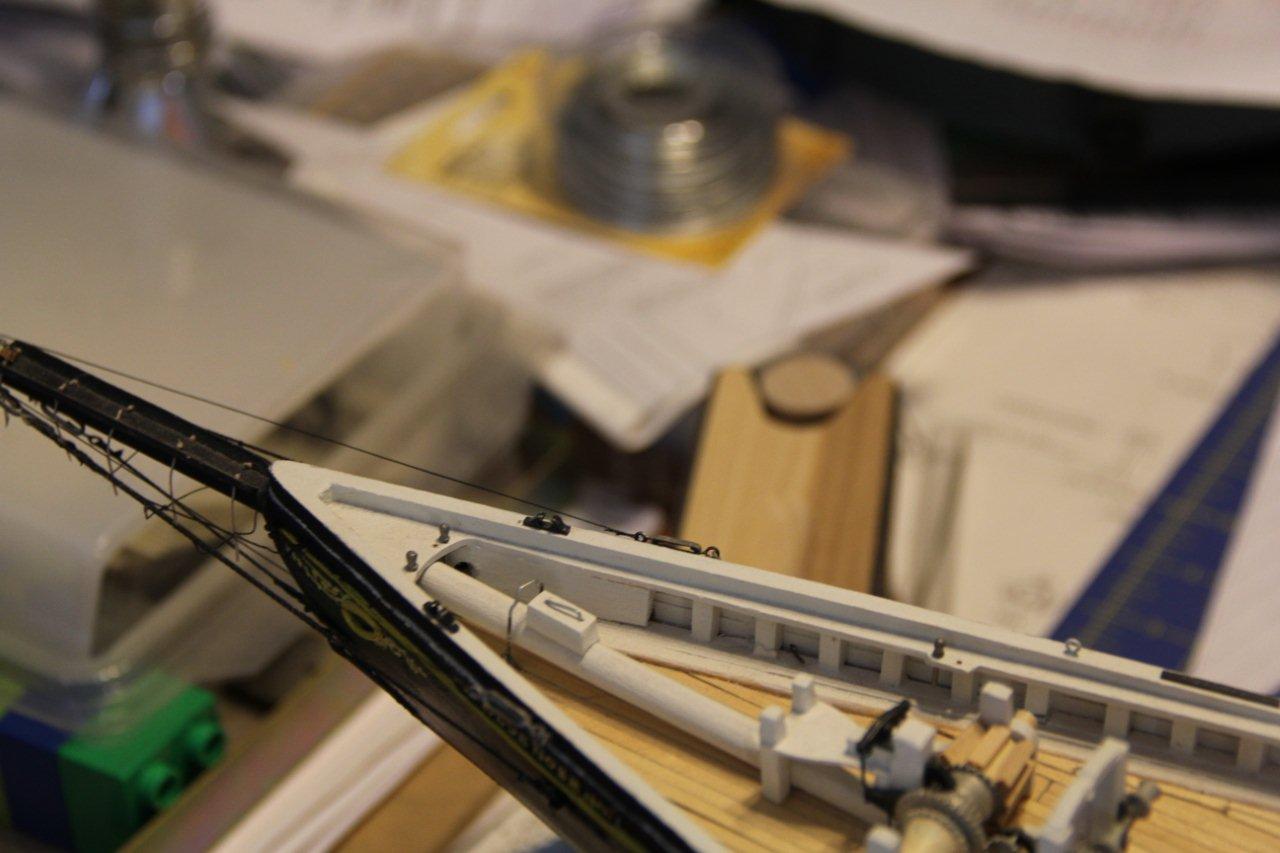
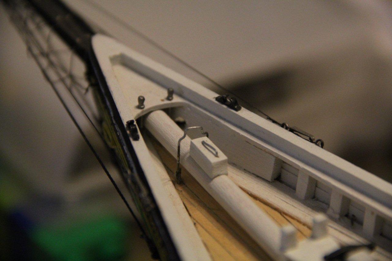
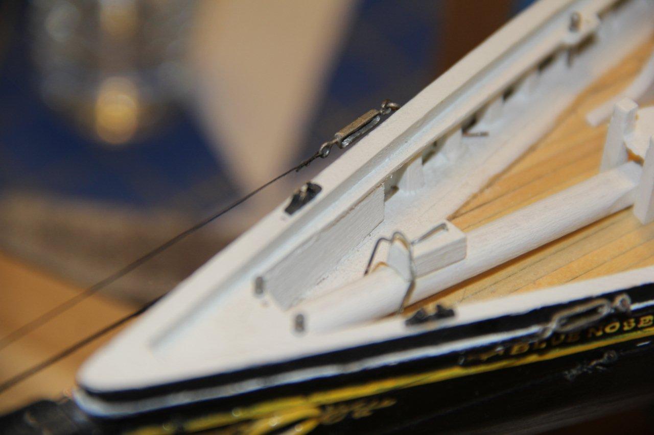
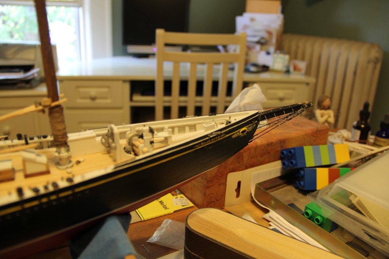
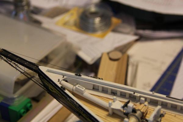
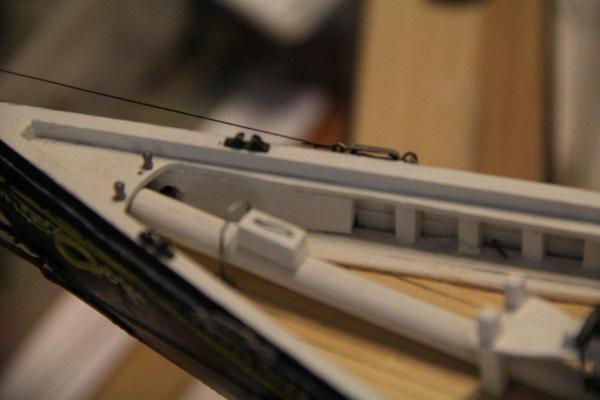
Jan-Willem Here are the photos you requested. Hope it helps. That solid block you see runs all the way to the stem where it wraps around the bowsprit. I think the stanchion count is accurate. I suspect that not every frame is continued above the deck so the number of stanchions is less than the number of frames. Enjoy, and let me know if I can share anything else with you. Bob


-
Jan-Willem - Thanks for the kind words. It has been fun adding some of the detail from the MS plans and the photos from the Nova Scotia archive site. I need to charge up the batteries on the camera and will attach some photos of the area soon. Unfortunately, that area was one of the first areas I built on the model, so it in not well detailed on my build. I basically used a solid block of kit wood to fill in the space where these details should be. If I was to re-do the section I would attempt to include the details of each separate piece of timber. BTW when I count the number of stanchions on the model (and the MS plans), there are 30 between the stern and end of the quarterdeck, and 25 from the break between the quarter- and fore-decks and the beginning of the hawse timbers. Don't be afraid to put in a mess of them! Michael - I am happy to say that I have NOT be sucked headlong into the CAD world. However the build has pretty well ground to a halt over the past few months. Parts of it is other priorities taking up time, part is my natural tendency to over-analyze and over-think when I move to something I have never done before on a model - and sails is a whole new thing to me. I am in the midst of a sort of analysis paralysis mode at the moment until I get up the courage to actually transfer some of those templates to cloth. Dimitris - sorry for the late acknowledgement. Thanks for stopping by and for the kind words. Bob
-
Nice decision, Darrel. I think the extra work pays off in the final result. You are about at the point where I was when I started to drop away from Hunt's practicum and spending more time looking at the plans for details. Keep up the nice clean work. Bob
-
You have a very nice base here - 16 years well spent . I identify with the comment about procrastination. It is hard to attempt something new and different when it comes up. Looking forward to where you take her next. Bob
-
Simon This is a very nice start to your build. Good clean lines and a symmetrical shape. About covering the paint, putting a coat over the finish will protect it from dings and scratches. I have to admit, I haven't over-coated my hull yet, but I do have a can of Minwax Wipe-On Poly on the table and may get to it someday. I am planning to use the clear satin finish, which may knock some of the sheen down, based on the pictures. Don't worry about how fast or slow you are moving - I've been at mine on and off for 7 years. When the mood strikes I work on it, when it doesn't she sits quietly and waits for attention. Bob
-
Dave - it's good to see you starting up a new build. Endeavor looks like an interesting subject - I will be following along with great interest. Bob
-
Coppering the 1:64 Syren
bhermann replied to rtropp's topic in Building, Framing, Planking and plating a ships hull and deck
Richard - I saw Thomas' reply and then checked out his coppering. It does indeed look really well done. And yes, you ARE a glutton for punishment! Enjoy the journey. Bob -
Ed The Canon I use has the ability to set a time delay of 2 or 10 seconds between pushing the shutter release and actually opening the shutter. That allows a few seconds for any shaking to die down before the exposure begins. It also allows you to set up a shot, then move into the photo yourself, if you want to do that. The remote shutter release provides the same elimination of camera shake - by keeping your hands away from the camera while releasing the shutter. Mirror lock-up is a different matter. When the shutter is released, normally the mirror that directs the input to the viewfinder moves out of the way immediately before the shutter is opened. This allows the image to be directed to the sensor instead of the viewfinder. Sometime that mirror "bounce" can introduce a bit of shaking as well that could be noticed in long exposures. Mirror lockup allows you to compose the shot through the viewfinder, then swing the mirror out of the way and delay the opening of the shutter for some time afterward to allow that shaking to dissipate. I certainly don't see any sign of shaking in your photos, so just keep doing what you are doing! Bob
-
Latestarter No such thing as a stupid question. Sometimes when a new question is asked inside a topic that was already started, it is easier to miss. In any case, here is what Pete did - check the first post in the topic for a pretty complete description of his process. Hope this helps. Bob
-
Ed Finally something i can comment on! AV priority is my favorite photo mode for just about everything (except astrophotography). I love getting photos with decent depth of field and that is the best way to do it. Is that a remote shutter release I see? If the camera has a shutter release delay setting and mirror lockup (assuming it is a DLSR), sometimes you can use those features to eliminate camera shake when releasing the shutter. By the way, the ship construction is just fascinating to me. I love seeing the details of everything that goes into one of these behemoths. Combine that with the amazingly graceful lines of the clippers and you have a combination that can't be beat. Thanks for sharing to the level you do - it is a real inspiration for me. Bob
-
Coppering the 1:64 Syren
bhermann replied to rtropp's topic in Building, Framing, Planking and plating a ships hull and deck
Richard - The only thing I am verifying here is your math. 1/4" scaled down 1/64th is indeed .00390635, (or about 4 1/1000s inch among friends). The 1/32 nails you have are 8x too large. My thought is that you are reaching the point where you may want t consider leaving the detail off entirely. There has been a lot of discussion around coppering lately and I recall reading that on the real thing the nails were set flush with the plates. At 1/64 scale you are at the point that anything you do will be too large and it's something that probably wouldn't show at this scale. Having said that, I've seen instances where modelers have put dimples into their copper plates and the effect looks very good. In the end, it's your ship, it's your call. I look forward to seeing what you make of it. Bob -
Rusty, I go away for a few days and find - THIS! Well done - I love that the final display shows so many of the structural elements while still giving a feel for what the completed section would look like. As always, that's some very clean and precise work! Bob
-
Dimitris - She is looking really fine - lots of nice details and finishes. I particularly like the painted scroll work around the hawse hole. Very sharp and clean. Looking forward to more photos. Are the booms and gaffs up next? Bob
- 57 replies
-
- 1
-

-
- bluenose ii
- artesania latina
- (and 2 more)
-
I've noticed that stiffness when rigging the bowsprit. Putting tension on with weighted hemostats and using simulated splices did the trick there. Not an option for lanyards, I'm afraid. The stiffness was the main reason I purchased a bunch of Chuck's rope - haven't tried it yet but I'm hopeful for better results. Bob
-
Nice work on the blackening - and the shrouds. I'm sure I'll be running into the same issue with the lanyards when I get to that point and will be watching for your results. The only additional thought I have is filing a grove on the deadeye that follows the path the lanyard will take. With the deadeyes already installed that may not be advisable - and I don't really know if it would do any good. Just some thinking aloud here. I tried to remember to do that when attaching blocks, until something is actually rigged I'll have no idea if it did any good. Bob
-
Fantastic build! I will be waiting for Royal Louis along with a bunch of other folks, apparently. Great job and congratulations. Bob
-
Popjack - like you I noticed the internal stropping of the blocks. I decided to try drilling holes for the hooks and eyes that needed to be added to blocks. I used a #74 drill (or thereabouts) with a pinvise and CAed the hardware into the block. I have been able to do this with all the sizes of blocks included in the kit. I am using 24 gauge galvanized steel wire at the moment although some of my early attempts used the brass wire included with the kit. After getting the hooks on the blocks and hanging them on their eye (or bail or whatever) they kept annoying me by falling off with almost no provocation from me so I decided it was time to mouse them. My first attempts were pretty clumpy looking but I kept at it until I liked the look. I used Coats and Clark cotton-poly blend thread and took the strands apart to get a single filament line to use for mousing. I think my later results look pretty good. Here is a photo of the foremast top with several blocks moused in view. (If you don't want me to clutter your log with photos, let me know and I'll pull this one.) I think I had the mousing process documented in the MSW1 log, I'll have to add it to the new version if I find I haven't done it already. Bob

-
Johnny For tapering spars without power tools here is a link to how I did it for my current build. Check out this post and the one following it for two different types of taper. I am just getting to the rigging phase myself, so I don't have anything to offer on that front. http://modelshipworld.com/index.php?/topic/217-bluenose-by-bhermann-model-shipways-2130-164/?p=11773 Bob
-
Mantua Albatross - mast rings question
bhermann replied to Jsh112bc's topic in Masting, rigging and sails
From the photos, it does indeed look like the builder wrapped the mast with a continuous length of wire. That doesn't mean you have to do it that way. Individual mast hoops is probably the better way to go. In my opinion in the absence of sails, the mast hoops should be stacked at the bottom of the mast, not magically suspended at equal spacing along the mast. Bob -
Yes, please! More detail on how the sails are done. You are showing some fine work here and the details of how you are doing it would be greatly appreciated. Bob
-
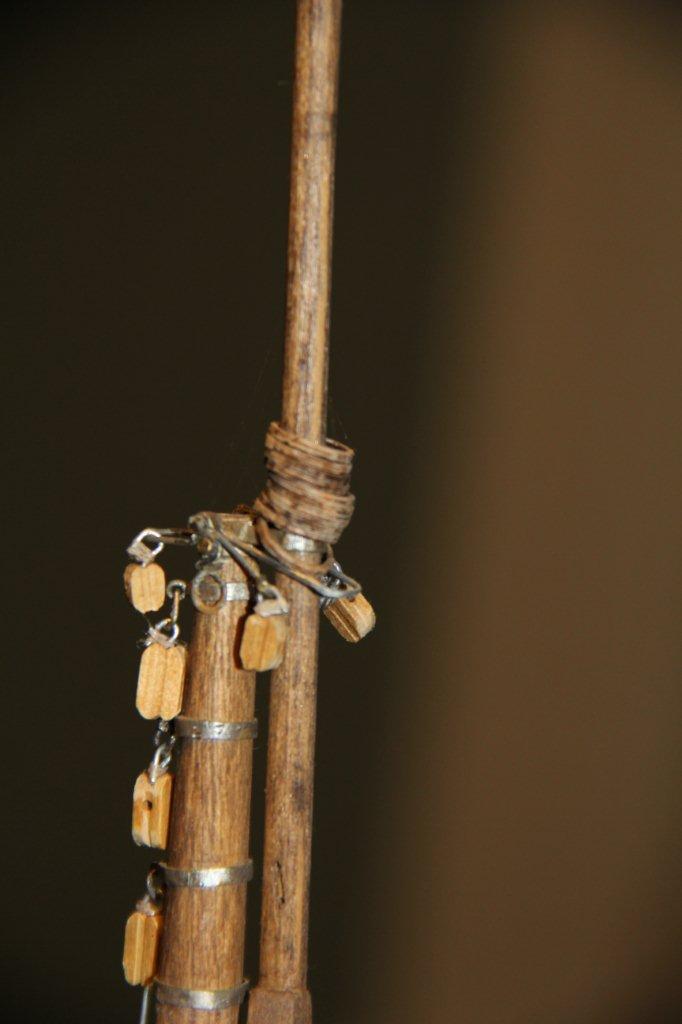
You scared me with this one - then I took a closer look. Is that the band for the spring stay bail on the fore mast? There certainly is a lot of hardware up there. That hole and pin running through the mast will hold everything together. Better that you found it now that later when you are trying to rig the stay! Bob
-
No progress here - just a lot of staring at sail templates and contemplation. I did take advantage of Chucks discount for MSW members and ordered up some rigging line. Maybe that will help me get out of the doldrums! Bob