


bhermann
-
Posts
549 -
Joined
-
Last visited
Content Type
Profiles
Forums
Gallery
Events
Everything posted by bhermann
-
Sorry for creating the confusion, Bob. The plans I have show two tack lines for the fore topsail, one run to port and the other to starboard. As with the jib tacks, the corner of the sail is pulled over the top of the spring stay (and the mainmast stay) when tacking. The tack line that is not in use remains draped over the mainmast stay. Bob
-
Hull planking - was done mostly in my lap. (What can I say, I didn't know any better!) Bob
-
Shawn - the trick is to look at it from the side with your eye at the level of the waterline. If it looks straight from that angle, you've got it made. Nice progess on this guy - keep up the good work. Bob
-
Sign me up as a member of the "old t-shirt club" too. Very clean work Rusty - enjoying watching your updates. Bob
-
Bob Are you looking for information about the staysail that is rigged between the fore topmast and the main topmast? I have also seen the sail referred to as the "fishermans sail". The rigging plan for Bluenose indicates that it needs to be lowered to the deck to be switched from one side of the spring stay to the other. There are two sets of staysail halliards rigged to the main topmast to accomplish and the staysail sheet is belayed either port or starboard depending on which tack the ship is on. I spent a lot of time looking for this answer when I was considering whether or not to rig the sail. I don't know if it is safe to generalize from that - I'm sure others will chime in with more definitive information. Bob
-
Elia - that cove line section looks VERY crisp now - nice re-work The rest of the details shown also are very sharp. I will have to look into the Woodland Scenic transfers - they seem to be a nice addition as well. Bob
-
PopJack - The Nova Scotia archives have some photos of the ship that have been helpful in working out some details. I was able to find this shot of the cabin. it's not entirely clear but it is a start. http://www.novascotia.ca/nsarm/virtual/bluenose/archives.asp?ID=203&Language= There may be other photos that show the cabin better - take a look around some of the other sections there. Someone (Fritz Koopman, I believe) posted a description of the paint scheme by a local ships captain in my log on MSW1. If anyone saved that, it moght have some useful information. If Fritz sees this, maybe he will re-post the information here. Bob
-
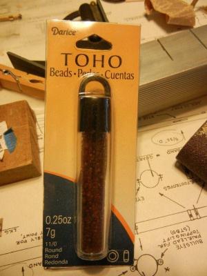
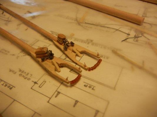
BEADS - another use for beads is as parrel beads for all those gaff rigged schooners out there - or other applications where there are single parrels in use. Steve - great thread - may I suggest you change the title to something that might help people realize what you are trying to do with it? It will help get more responses, I suspect. Thanks, Bob
- 396 replies
-
- 9
-

-
- Idea
- Bright Idea
- (and 1 more)
-
Size of blocks for MS Bluenose 1/64 scale.
bhermann replied to DaveGrady1's topic in Masting, rigging and sails
Dave - I'm sorry to hear the blocks are no longer supplied. It seems that several things have disappeared over time (the walnut veneer for the second planking was the first item I am aware of that went missing from later kits). My older version does have the 7/32 blocks included. They look a bit oversized to me. If you are going to purchase blocks I'd recommend going down in size - the 5/32 might do the trick. Are there enough of those in the kit to substitute for the halyard blocks? Or as Allan said, making your own blocks is an option. There are some threads on MSW that describe peoples techniques for doing this. BTW - I'd love to see photos of your work so far - or even a build log if you are of a mind to do so. The more Bluenoses out there, the better! And welcome to MSW. Bob -
Jay - I bought the paste from Amazon. One tube goes a long way in this line of work. Bob
-
Size of blocks for MS Bluenose 1/64 scale.
bhermann replied to DaveGrady1's topic in Masting, rigging and sails
Dave - if this is the Model Shipways kit, I'd suggest reaching out to Model Expo for replacement parts. They have always replaced missing or broken parts for me with no questions and at no charge. Bob -
Jan - I think the gold figures on paper came out very well. They stand out better than the original attempt, and blend nicely with the rest of the ornamentation on the transom. Good fix! Your sculpting work looks marvelous to me. Keep going Bob
-
Jay - I have used a similar setup in making the eyes, bands, and lugs on Bluenose as the last section you showed using the small torch and silver solder. The only difference is that I am using silver solder paste that includes the solder and flux so they can be applied at the same time. It is amazing how strong those silver soldered joints turn out. Bob
-
Congratulations, Sjors. She turned out so well. I think the shots of the bow and stern really highlight her gracefulness and your craftsmanship. Well done! Bob
-
I've been rationalizing that the rigging thread will run on the inside of the hole and that it won't snag on the wire. I have also been trying to drill out the end of the wire after the hook is glued in place and set up. I'll soon be coming to the point where I'll have to test to see if I've just been fooling myself! Thanks for the tip on using the shank. I think I would have caught that, but probably missed the idea of moving it to make sure it doesn't become a permanent part of the block. Bob
-
That is a nice looking skylight. A similar approach to the main cabin would probably work well also. Painting the inside of the box black gives it the proper feeling of depth. Hmmm,,, time to re-do what I've got in place? Bob
-
Thanks for posting that, Jay. I have done similar things with gluing hooks onto the short side of blocks, but never thought of putting a rod through the sheave hole. Not only does that prevent glue from filling the hole, but it keep the end of the hook from blocking the hole as well. I'll have to remember that one for future blocks! Bob
-
She is looking good, Popjack. It was about the time I was building the deck furniture that I noticed the practicum didn't agree with the plans for painting. I made the forward companionway and skylight in accordance with the practicum then ditched it for color schemes. Also the plan calls for the tops of all the rails to be white, while the practicum calls for black. I ignored the practicum for that as well. It is surprising how much the waterline appears to dip toward the bow - the drag of the keel makes that more pronounced. All i can suggest is to look at it from the side and see that it looks straight from that angle. I reworked mine after initial painting to get it better. Bob
-
Hi Frank. Thanks for stopping by and for the kind words. I too have been following B.E.s Pegasus - now there is some real craftsmanship! As Bluenose is my first wood build, it didn't occur to me that research would be useful - or even possible - until I was a ways into the build and after I found MSW myself. Since them my primary source has been the Nova Scotia Archives section on Bluenose. The articles and especially the photographs have been very useful in sorting out some of the details as I have gotten further into it. I haven't seen anything there on Gertrude expect some race photos showing her from a distance. I assume you are referring to the "Gertrude L. Thebaud". If you haven't been searching on the full name, that might yield better results for you. Also check out the Story Shipyard in Essex, Massachusetts, where she was built. I look forward to hearing about your experience in looking for her, and to your build log, should you get the chance to do that. By the way, I understand your respect for the underdog and I share it. I have to admit when I started this build, I didn't even know there was an underdog to the Bluenose story. I just loved the lines! Bob
-
Hi Kip, it's great to hear from you. I guess I'll have to see about getting a copy of the Jenson book after all. I forget who it was that speculated about a lazarette on MSW1 - guess they had the right idea! Bob
-
Roger - I believe the Jenson book contains drawing of Bluenose II, which does not have the same deck layout as the original. There is no evidence that a scuttle existed at that location on the original. I think we are still in the dark on the "round object" on the original. Other differences between the original and BN II that are apparent on the drawing you posted: on the original there was a hatch behind the mainmast in the position the Jenson drawing shows a companionway. Also, the cabin on the replica is longer than the original, running the length of 15 frames, where on the original it only ran 9 frames in length and left a larger deck space between the cabin and the mainmast. Thanks for sharing this information, but I think the hunt for the answer still must continue. Bob
-
Rob - I have been enjoying the resurgence of clipper models also. Thanks for sharing your build with us. If I ever get Bluenose finished, I'll be adding my Flying Fish kit to the mix. The box is sitting in the corner trying to tempt me to open it and do more than just study the plans and read the book! Keep up the great work - love the work you are doing. Bob
-
Seizing or whipping a line. Here is how I have done it.
bhermann replied to Modeler12's topic in Masting, rigging and sails
Jay - I noticed that the thread was still taped after hearing the words so I figured you were getting a little ahead of yourself. Loosening the taped thread at that point would have left you with one hand too few! Bob -
Daniel - it's good to see you finally keeping one for yourself. I am curious what you are thinking about using for ratline material, at this scale it'll have to be mighty thin. I'll be following along. Bob
-
Seizing or whipping a line. Here is how I have done it.
bhermann replied to Modeler12's topic in Masting, rigging and sails
Jay - thanks for putting this together. I have read descriptions of that technique several times over the past few years, but seeing it being done really helps clarify what is going on for me. Thanks, Bob

