


cookster
-
Posts
416 -
Joined
-
Last visited
Content Type
Profiles
Forums
Gallery
Events
Posts posted by cookster
-
-
Thanks Bob. I don't know how remarkable it is, but thanks for the generous compliment. It's still not a true POF model and I'm definitely cheating on lots of things. The guys that build true POF are the experts. Baby steps I guess
")
Hopefully I'll get this bow section done soon, I'm ready to work on something else! But, I knew I would struggle so it's no surprise...
-
Great start Mobbsie, good luck moving forward!
- Canute, popeye the sailor, mobbsie and 1 other
-
 4
4
-
Beautiful work as always Bob!
-
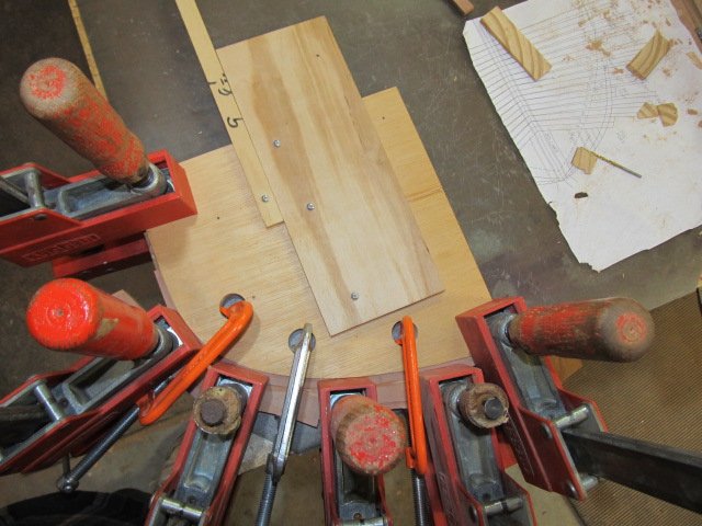
I used a "few" clamps to clamp up and glue the knee and stem
Since my last visit last year I have redone the can frames and hawse timbers again, now I am on version 3. Version 2 worked, but I discovered I had incorrectly shaped them. No one but me would've known, but I knew I could do better. I think the version I have now will work and I will be mostly satisfied. I don't think I can do any better, especially since these are based from plans I developed that I "hope" are accurate.
Here is version 3
Still a long way to go before I finish them...
- albert, archjofo, CaptainSteve and 6 others
-
9
-
Hi All, I'm back again. My apologies for another long break away from MSW and ship modeling. Sometimes life just has other plans...
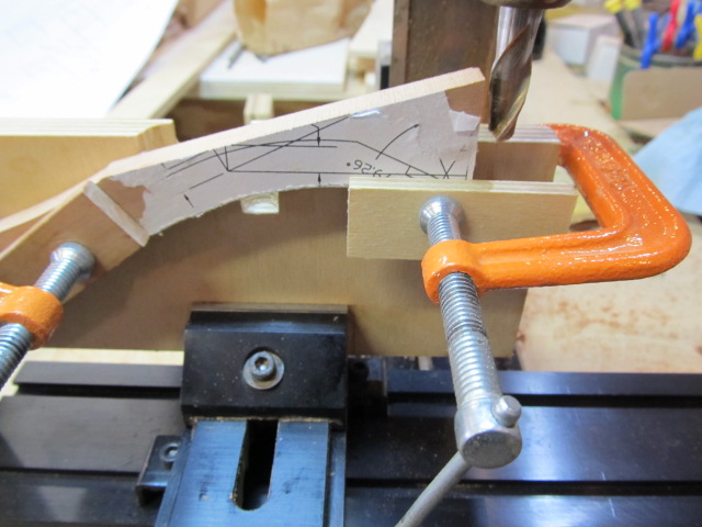
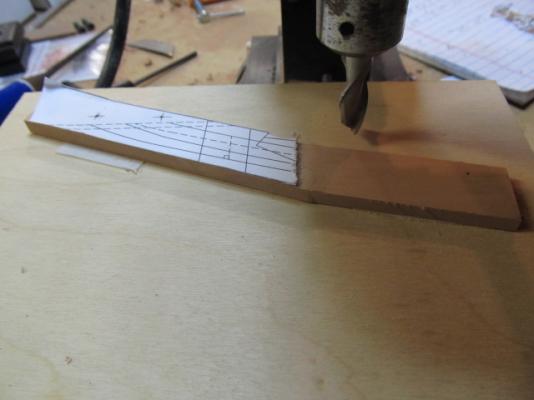
Anyway, I've made additional progress on the stem and knee of the head, using my mill to cut out the joints.
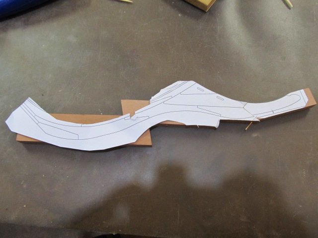
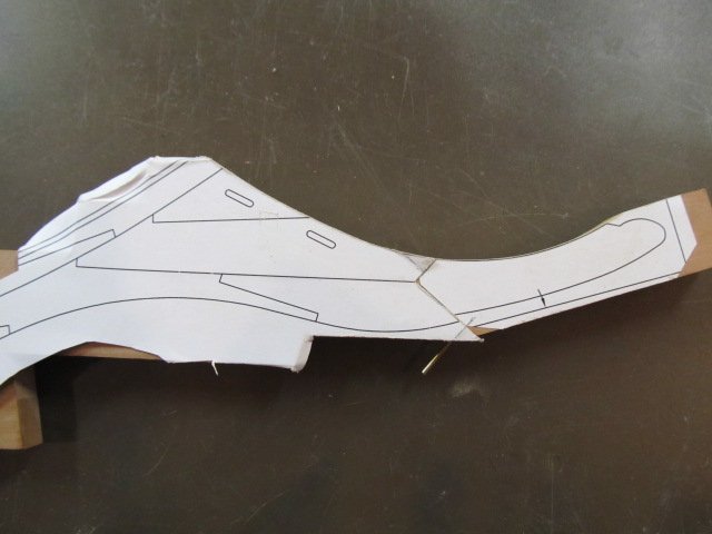
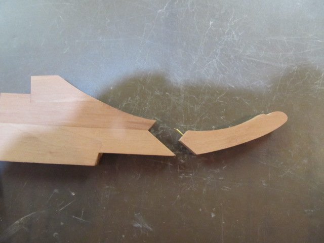
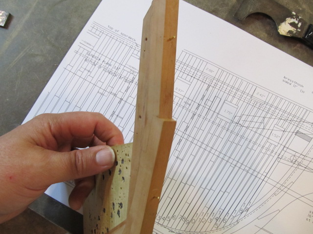
Here's the stem and knee of the head so far, not finished yet
- GrandpaPhil, CaptainSteve, mtaylor and 1 other
-
4
-
Just found this. Thank you, Thank you, Thank you!!!
- Canute, CaptainSteve and mtaylor
-
3
-
-
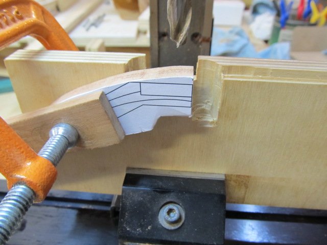
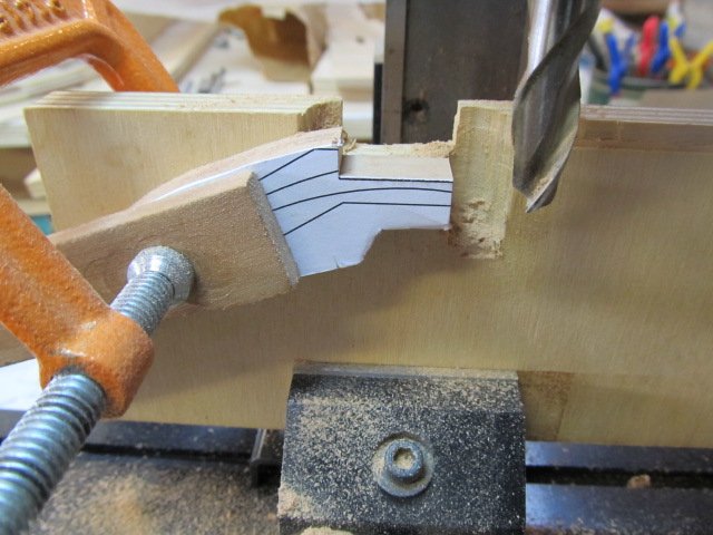
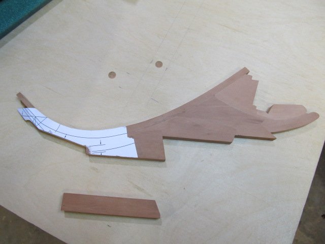
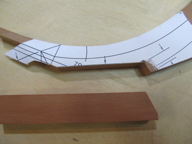
I'm again using the template routing method. I've described this before so no need to do again.
Few more pics
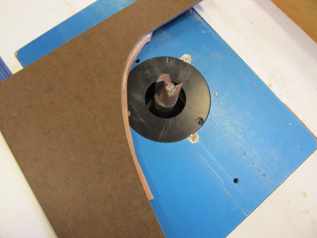

Here's milling the foot. It's not prototypical, but it's how I'm going to make it.
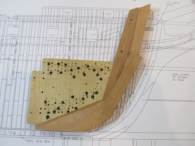
Here's the back of the knee against the stem.
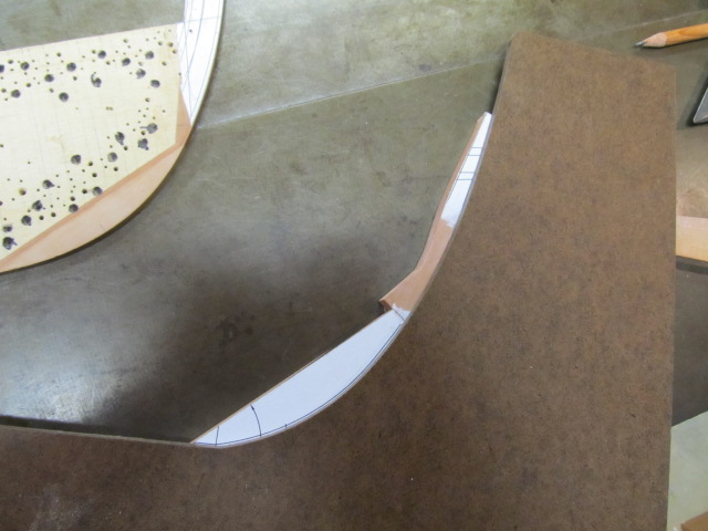
And started shaping again. I hope THIS is the last time I have to do this.....

-
Past time for an update. Since my last post I found my cant frames and hawse timbers were not shaped correctly. I had sanded them too narrow. Part of this error was a drafting error on my part, and the rest was from too aggressive sanding. So after much thought and frustration, version 3 was started.
Here's a pic of the amount of error. It's not small....
I could've moved on with the shape as it was and no one would've known, but it would've bothered me forever and i didn't want that. Also I've gotten pretty good at making cant frames, (as I've had so much practice....
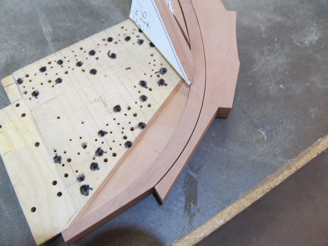
 ) I decide it would't be so bad. This time I'm following a more conventional process on the hawse timbers and am making them individually, instead of as a group as I did before. This should allow me to get a more accurate shape. I'm also using Ed Tosti's method of templates on both sides of the frames. I hope this increases accuracy.
Here's a few pics before any shaping.

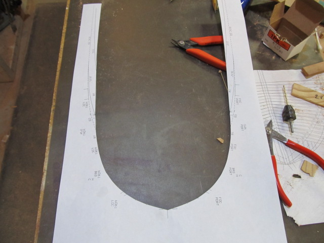
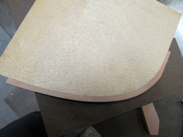
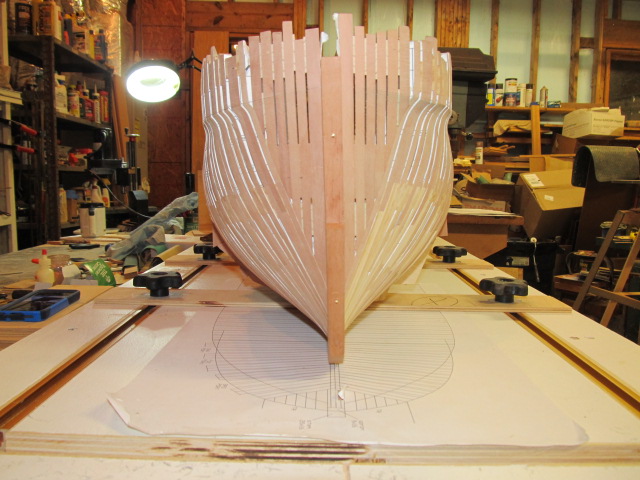
This time I'm also making and using using templates of the hull outline at various heights, again to try and increase accuracy.
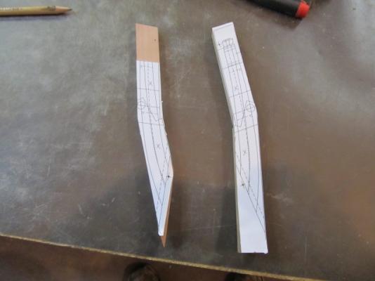
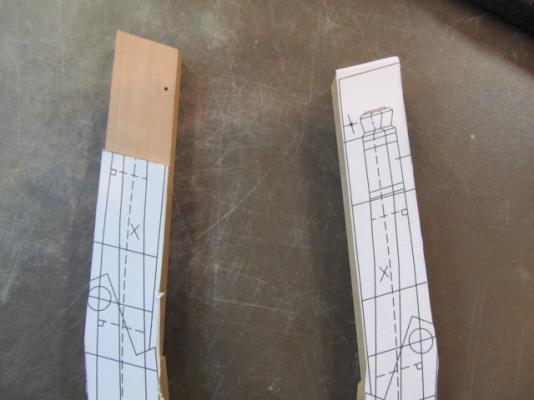
I'm also working on the knee of the head, finally something different!
Here's a few pics of the pieces in various stages. I haven't finished the head yet.
- mtaylor, CaptainSteve, Mike Y and 5 others
-
8
-
-
Thanks everyone!
Mike, yes pins and screws are doing the job. I use #2 screws to secure the cants to the center bulkhead, and the pins are for alignment. I've seen many folks on MSW use that method, I can't take credit for it.
Greg, coming from you that's an supreme compliment! You are one of the builders I strive to emulate.
-
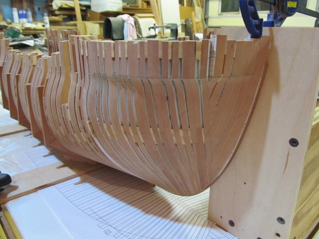
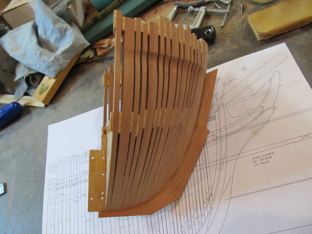
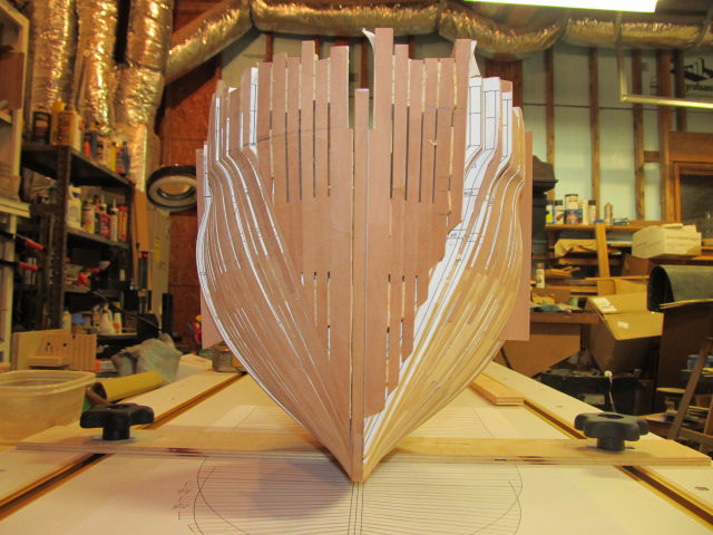
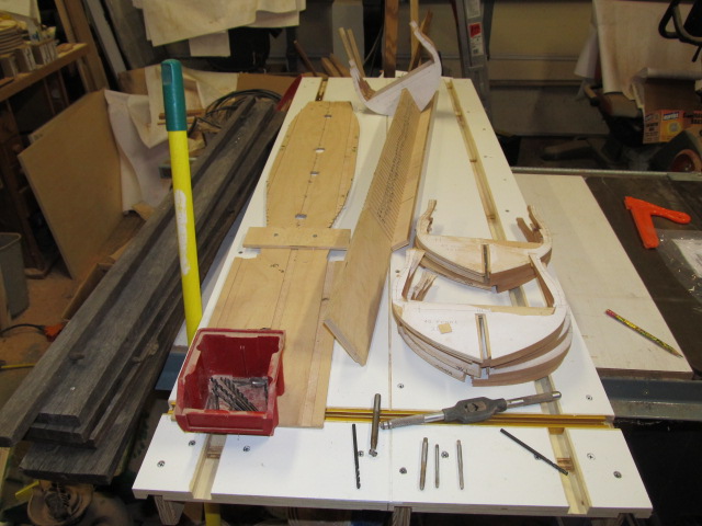
And finally, I assembled it all back together (temporarily) to see how she looks. The cants, hawse and bollards are now rough faired on the outside face. I took a bunch of pics so pardon the photoblast.
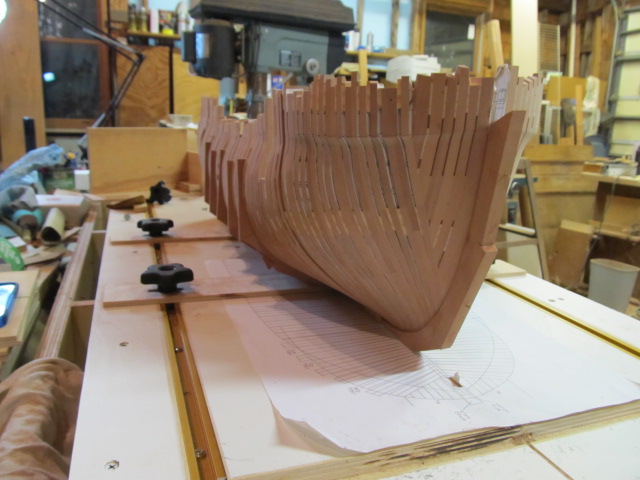
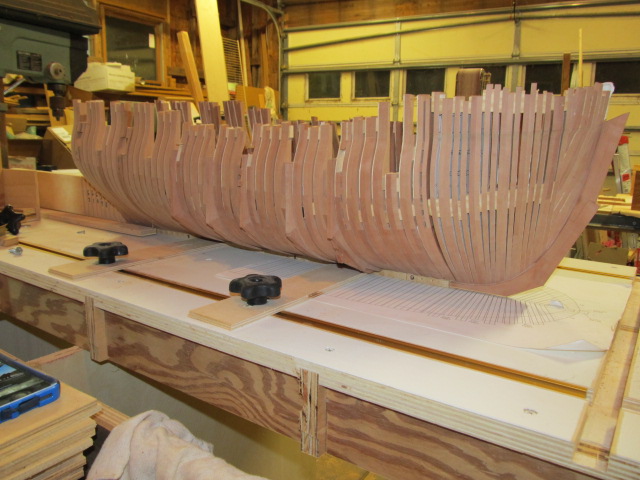

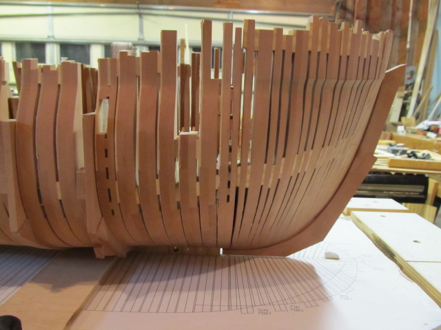
Soon I'll start shaping and fairing the inside faces. I also need to finish drawing out the rest of the stem's various pieces, and start building it.
Thanks for the likes and for following along...
-
I finally got around to milling the foot on the stem. Here it is setup in the mill.
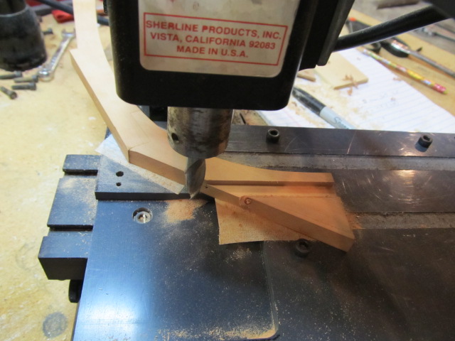
I mentioned way back the rabbet on the stem would be a "fake" rabbet. The way I fit the the center bulkhead, stem and bollard timbers makes a rabbet so I won't have to carve it. This is not prototypical, but for me it will work.
Here the stem is pinned on temporarily. You can see the where the rabbet will be.
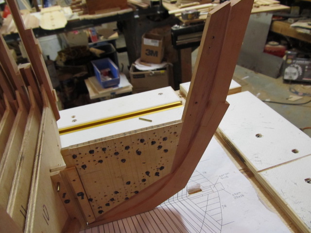
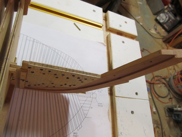

Adding the bollards and cants forms the rabbet.
- mtaylor, rafine, GrandpaPhil and 9 others
-
12
-
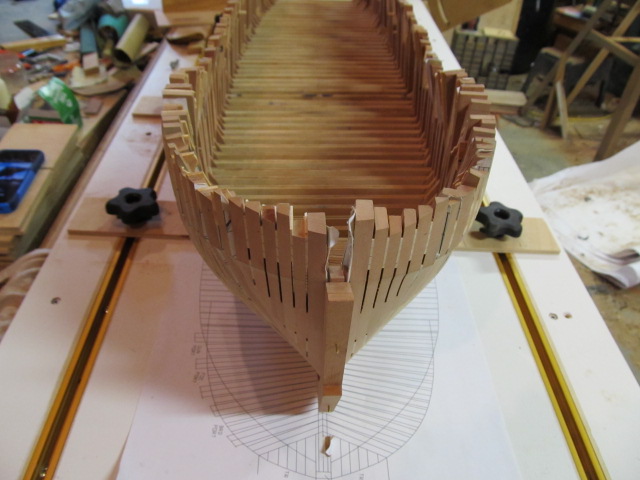
Mike, no, the frames are not glued to the bulkhead, neither are the hawse timbers. Everything is held in place with either brass pins or screws, and the square frames fit in the dados in the center bulkhead. The insides of the frames will be cutout on the scroll saw and rough faired, just as the outside was, off of the model, then installed and final faired by hand. So yes, there is still a lot of material to remove whenever I get to that point.
The paper patters will be as removed as late in the framing process as possible, they are only glued on with Elmers glue sticks. I want to leave them as long as possible for reference while building, fairing, and laying out things. I "stole" this method from many builders on MSW but most notably Ed Tosti. (who built and wrote the Naiad books) I've found Isopropyl Alcohol is great for removing the reside from the glue sticks. Water works, but much slower.
Thanks for looking in!
-
Per Bob:
"then a lot of planning will be necessary to ensure that the masts will line up with the channels, that the rigging won't cover up gun ports etc."
One of the rear gunports (sorry, don't remember which one) was fouled by the shrouds when she was built and was basically unusable. This is mentioned in TFEP (The Frigate Essex Papers). The rear gunports were moved during her 1808 refit to correct this issue and documented by Fox.
So, if you want to build her accurately as built a fouled gun port is accurate. If you want to do as Bob suggested and "correct" these issues then you'll need to work it all out yourself as Bob did.
Fun stuff, huh?
-
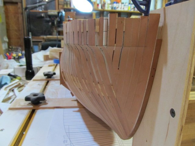
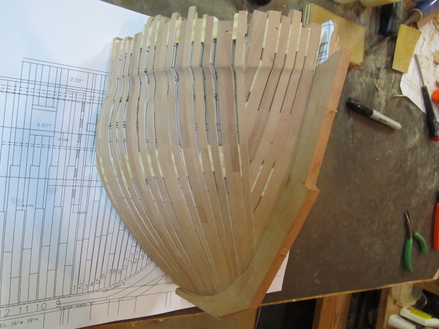
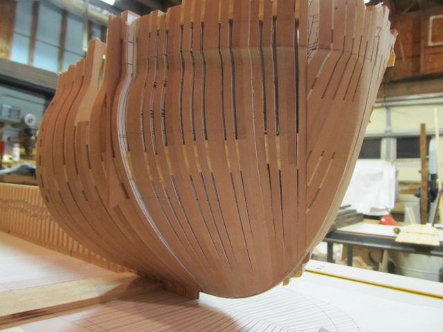
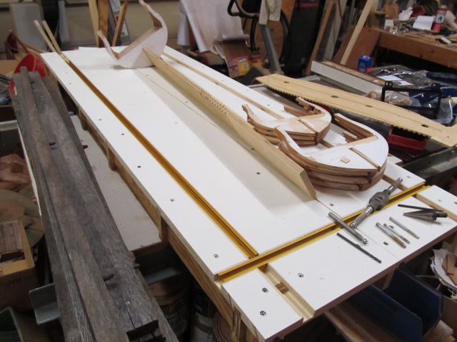
I temporarily attached the model to the buildboard just cause I couldn't wait. I still have to complete it and build several clamp blocks and such.
Here is work I had done last spring but never took pics of and posted.
The unplanked side is rough faired, the gaps you see at the joint between the feet of the hawse timbers and the first cant frame are only due to things being loosely held together. Trust me, the gaps are tight when assembled correctly.
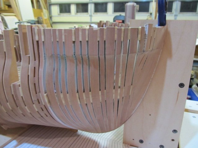
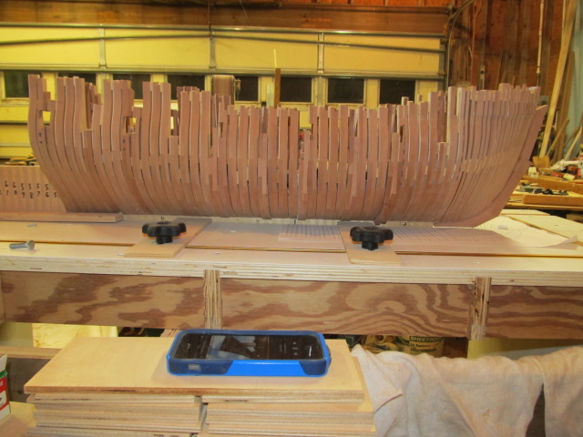
The unfinished side still needs to be rough faired. I also had to rebuild one of the square frames due to a stupid error I made when assembling them. Dopey me....
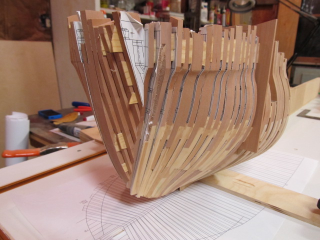
Here you can see the bollard timbers and the gaps between the Hawse timbers.
Now on to finishing the build board, a lot more sanding and the stem assembly. I cut the pieces for the stem last spring, I've yet to start assembling it.
- aviaamator, mtaylor, Mike Y and 9 others
-
12
-
Thanks guys!
I re-read back through this build log last night as It had been awhile since I'd looked at it, and I immediately came to and stopped on one of Augie's posts. Damn I miss his replies, witty banter and the encouragement he had for everyone, not just me. It really stopped me in my tracks for a few minutes as I read on and then saw his last post to this log. Makes you stop and think - at least it did me.
Anyway thanks again! I was gonna sneak in a pic of new progress but the camera batteries just died, so you'll have to wait a while longer...

-
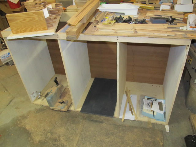
Hi all, I'm back after a long break this spring and fall. One of the reasons I quit working on Essex was I'd reached a point where i needed a build board and a new work table/bench. That's what I've been working on the last few weeks.
I've got the build board made, I just need to add one more piece of T Track.
Of course it's covered in clutter while I finish the new work bench.
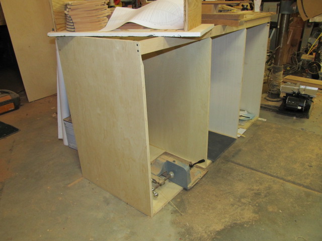
New work table. It will be portable, on casters. I debated adding casters but decided I wanted the portability, something I've never had in a work bench. I still need to add the casters, the top and the doors and shelves. I'll be working on that the next few weeks as I have time, then I'll finally get back to building.
Oh, and I finally got me a Byrnes saw for my recent birthday, now I can really get to scratchbuilding stuff.
As always, thanks for looking in....
- GrandpaPhil, Ryland Craze, Canute and 8 others
-
11
-
Hi Engineer57, I just found your build log of Essex. Welcome to the Essex (build) club. You're doing a fine job so far, keep up the good work!
As far as the drawings, there are several different versions out there, from several time periods. I don't have time at the moment to list all the variations, but the dwgs in the kit are (I think) still based on the dwgs Sam Cassano drew, which were taken off the original Hackett draughts. Portia T's dwgs I believe are not 100% accurate, but are close in many areas.
I'd say at this point you'll have to reconcile what you actually have built, where everything acts like it wants to fit and the kit's dwgs. I'm not sure you can achieve 100% historical accuracy on this kit (if that's even possible with Essex due to the many changes in her lifetime). I would trust Sam's dwgs, but I have no idea if the kit dwgs have deviated from them. Bob would be your best reference as he successfully built this kit - and did a damn fine job.
I am slowly building Essex myself, although my version is scratch built from dwgs I'm creating based on Josiah Fox's measuring of her after her 1808 refit, and William Baker's dwgs of her late in her life (based on Fox's measurements. I'm attempting to build her as she was in 1814, which is a lot different that she was when launched. Fox's measurements and Bakers dwgs, as well as a copy of Hackett's original draught are found in the book "The Frigate Essex Papers" but keep in mind they do not represent her as launched (except the Hackett draught of course). The kit I believe also has a copy of the Hackett draught, which one would hope is an accurate copy. I would definitely use that dwg as a reference.
Good luck, I'll chime in wherever I can!
-
-
-
Druxey, glad I found your build log. This is a very educational build. Seeing the hull in post #99 shows how graceful the lines are. Plus, if I hadn't read from the beginning to see how you got to that point I wouldn't have had a clue how you did it!
It's a joy to watch one of the masters at work....
Oh, BTW, I've looked at your avatar countless times, and never until today did I notice that's a quarter (I think) next to that tiny boat hull.... Gracious
-
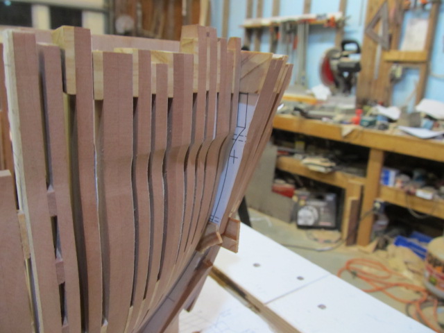
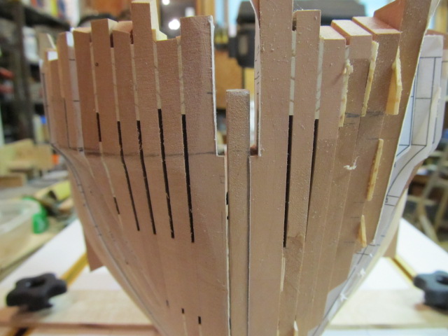
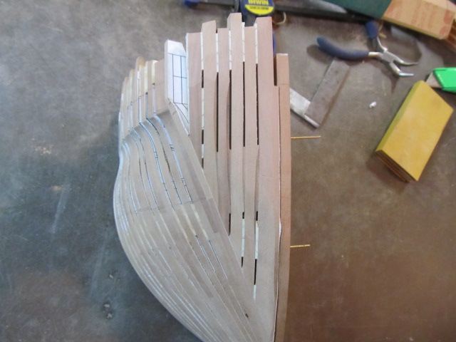
Here's the hawse timbers after some very rough shaping. Still a lot of sanding and shaping to do.
Hopefully this latest version will work out. I hope I worked out all the kinks on the first two attempts. Guess I'll know soon enough...
- Canute, GrandpaPhil, rafine and 9 others
-
12
-
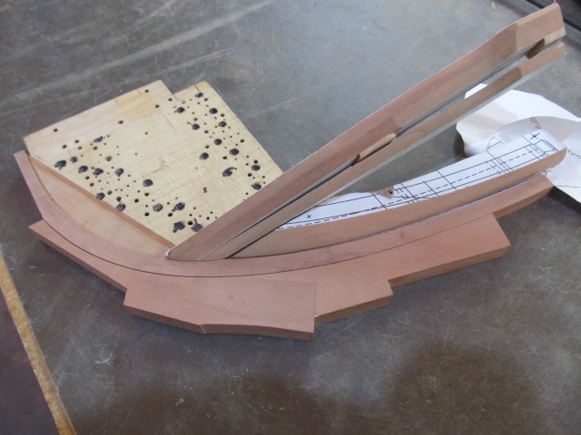
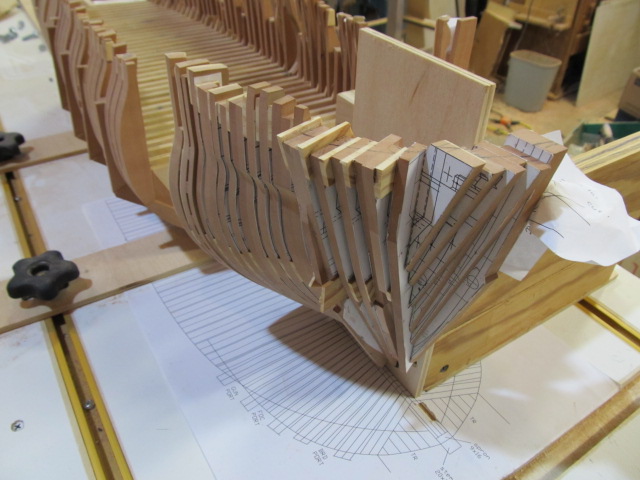
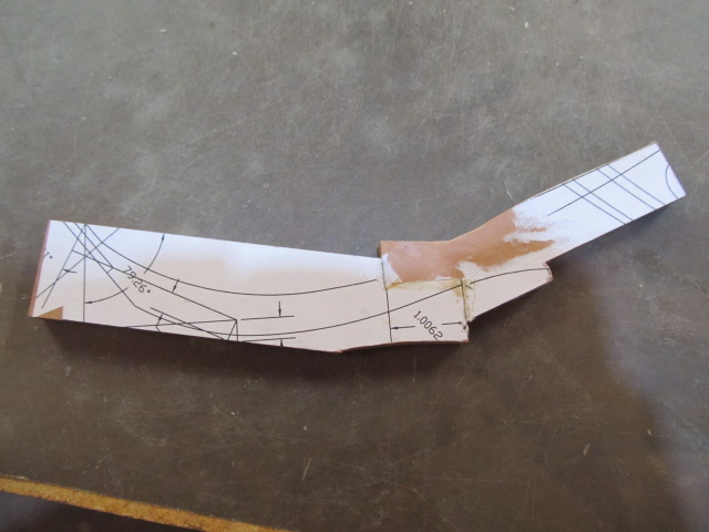
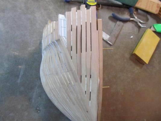
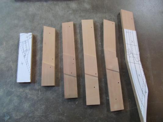
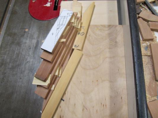
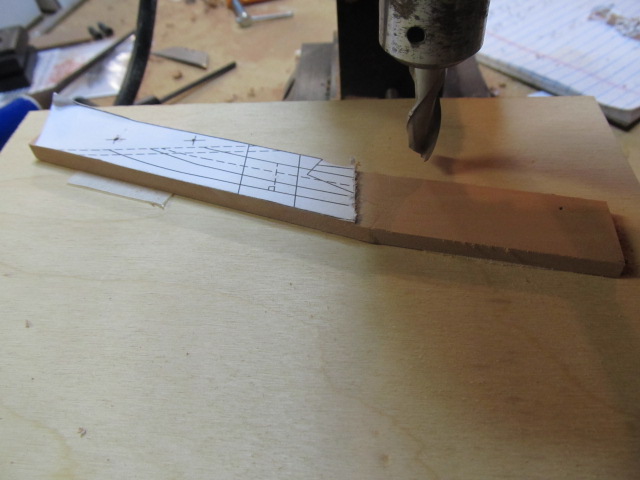
Here's an update on the hawse timbers.
I'm using templates of each timber, glued to each timber. I placed center marks for line up pins for use when gluing each timber together.
Since I'm now on version 3 of the hawse timbers I'm hopeful everything I've drawn will work out, so I went ahead and milled out for the air space between the hawse timbers.
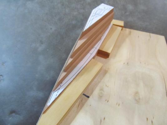
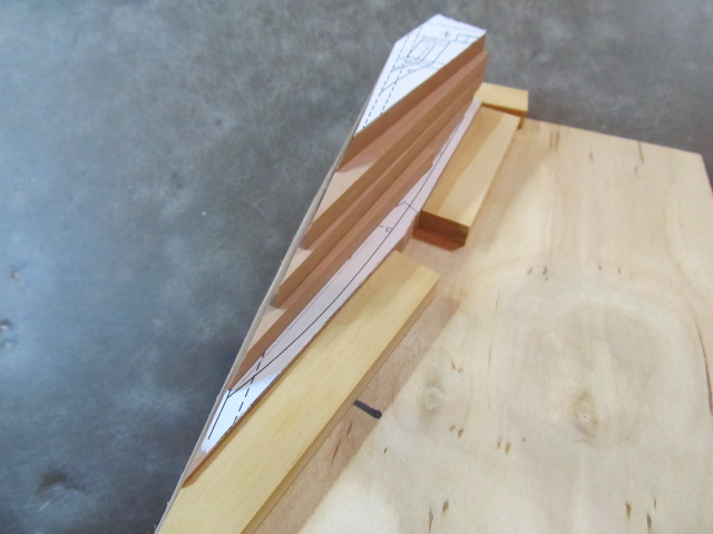
I glued spacers between the timbers to maintain spacing when gluing up. Here's brass rod as line up pins.
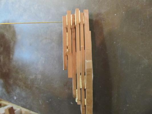
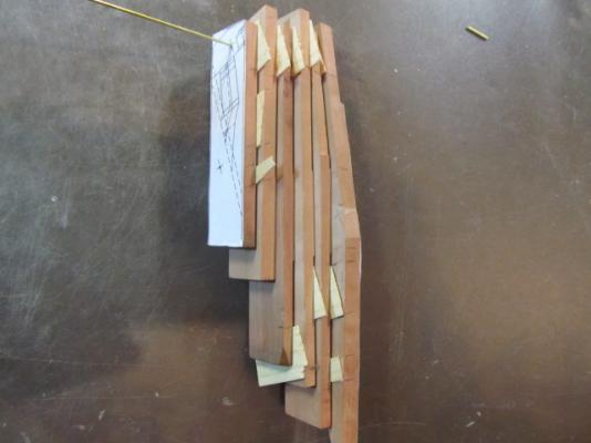
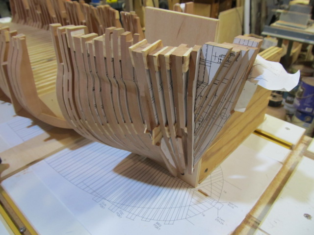
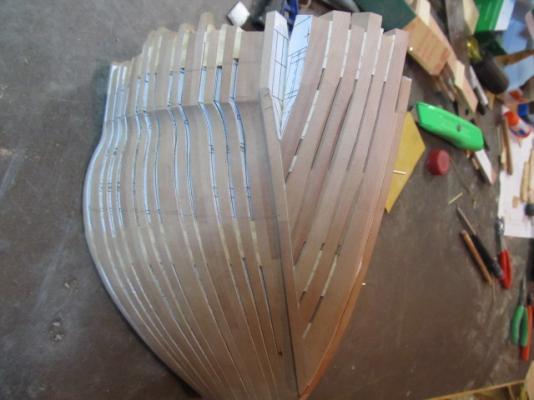
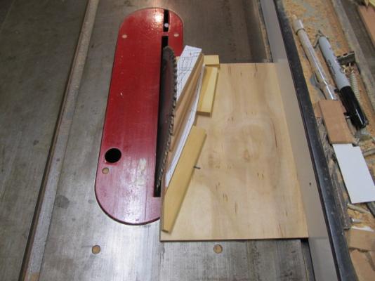
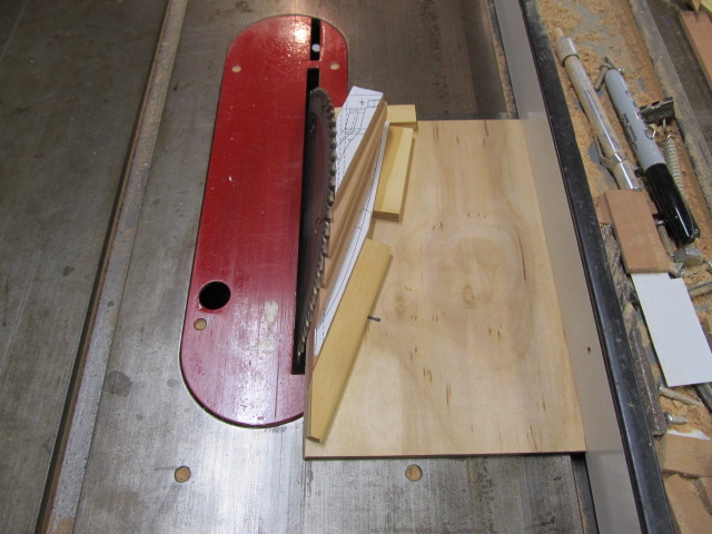
After all the timbers were glued together, I used a sled I made to cut the bevel that meets at the cant frames. This could be quite a dangerous cut on the table saw plus there was no way to accurately hold the timber assembly, the sled made it possible to do this. Also I wanted to glue all the timbers together, then cut the bevel. That's the most accurate way to make a cut of this type where all the individual cuts must line up.
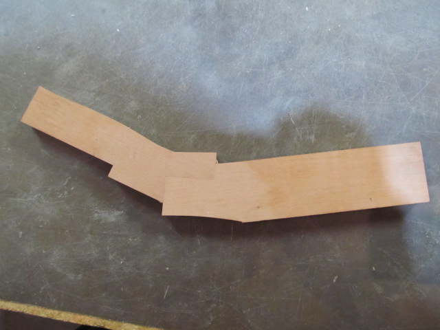
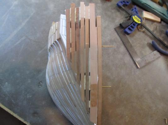
Here's better pictures from version 2 of the hawse timbers.
Here they are after cutting, pinned in place.


USF Essex by Cookster - 1:48, 1814 Configuration, POB and POF (first scratchbuild)
in - Build logs for subjects built 1801 - 1850
Posted · Edited by cookster
I began shaping the knightheads using knives, chisels and sandpaper.