


druxey
-
Posts
13,387 -
Joined
-
Last visited
Content Type
Profiles
Forums
Gallery
Events
Everything posted by druxey
-

HMS Euryalus 1803 by rlb - 1:48 scale
druxey replied to rlb's topic in - Build logs for subjects built 1801 - 1850
Looking very nice, Ron.- 122 replies
-
- 3
-

-
- Euryalus
- Plank-on-frame
- (and 4 more)
-
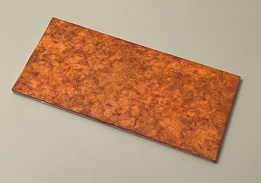
As a bit of light relief while making oars (five down, five to go!) I faux-painted a burlwood base for the model. There will be molding all the way around and a sub-base as well.
- 433 replies
-
- 20
-
-

-

-
- open boat
- small boat
- (and 1 more)
-
Shipman: Something in the order of 0.010" at 1:48 scale (I think that's was what you were asking!)
- 433 replies
-
- 5
-
-
-
- open boat
- small boat
- (and 1 more)
-
Keith: Theoretically 5/8", but they are actually a whisker thicker for integrity of the blade ends.
- 433 replies
-
- 5
-
-
-
- open boat
- small boat
- (and 1 more)
-
They are not complete yet nor bound with a metal strap to prevent splitting. All in good time, Roger!
- 433 replies
-
- 6
-
-
- open boat
- small boat
- (and 1 more)
-
Contour duplicators are much too large and coarse to be useful in model-making. Save your money, unless you are doing house reno's.
- 160 replies
-
- 2
-
-
- Model Shipways
- norwegian sailing pram
- (and 1 more)
-
HMS Euryalus 1803 by rlb - 1:48 scale
druxey replied to rlb's topic in - Build logs for subjects built 1801 - 1850
If the light balance is a little off, the joinery certainly isn't!- 122 replies
-
- 5
-
-
- Euryalus
- Plank-on-frame
- (and 4 more)
-
It is much better that the thwarts are too long than too short! No-one has invented a good wood stretcher yet. Card patterns are certainly the way to go, just as you suggested. Cut a piece roughly to the angle you need, then refine it by careful trimming. For complex shapes, you can glue small pieces of card to a larger one to get exactly the shape you need.
- 160 replies
-
- 5
-
-
- Model Shipways
- norwegian sailing pram
- (and 1 more)
-
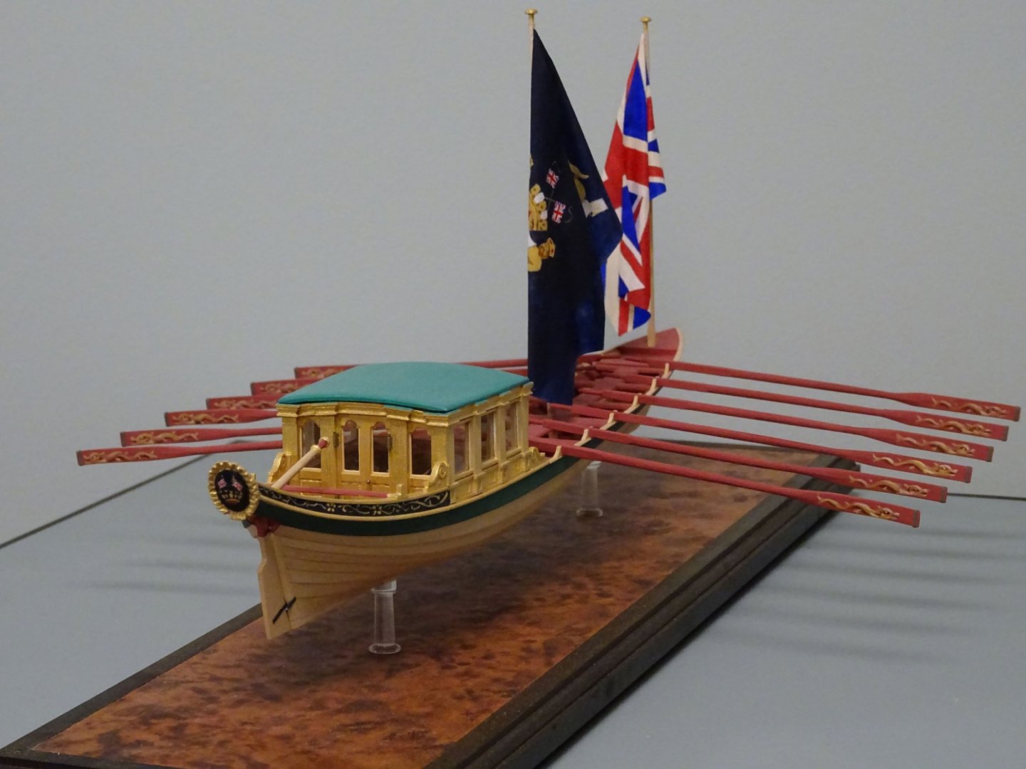
Good question, Greg. The oars will be deployed in the same way as the Greenwich Hospital barge model.
- 433 replies
-
- 16
-
-
- open boat
- small boat
- (and 1 more)
-
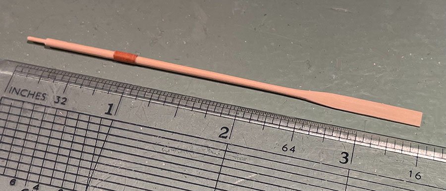
Thank you so much, folks. Pete: I, too, was once in awe of other model-makers. Slowly, bit by bit, I kept improving and learning. You can do it too! Pictured is the prototype for the 14' 0" oars. These are probably the smallest and most delicate I have made so far. I still have to add the binding on the end of the blade. One down, nine to go....
- 433 replies
-
- 23
-
-
- open boat
- small boat
- (and 1 more)
-
David: your tactic of placing a clamp or even a loop of seizing line on with the shroud pair in place, sliding it off and completng the seizing is a great strategy. It's worked well for me!
-
I found making a maquette (larger sized) in clay first helped me get the 3D problems worked out before carving in wood. It helped me visualize what to cut away. I agree that there is much more control with hand tools than with rotary power. Your banner holding angel looks good. The more carving you do you'll find you get rapidly better. (I shudder at some of my early attempts!) I also found looking at classical sculpture pictures helped me a lot.
-
Maury: Thanks for asking, but no, as it would not really add anything to what has already been published.
- 433 replies
-
- 5
-

-
-
- open boat
- small boat
- (and 1 more)
-
I'm amazed that you can get such clean edges painting on a woven material like that, Steven.
- 740 replies
-
- 5
-
-
- Tudor
- restoration
- (and 4 more)
-
Now you are just having fun! Very nicely realised details.
- 589 replies
-
- 3
-
-
- le gros ventre
- cargo
- (and 1 more)
-
ancre La Belle 1684 by Oliver1973 - 1/36
druxey replied to Oliver1973's topic in - Build logs for subjects built 1501 - 1750
I bet you were nervous drilling those hawse holes! Well done. -
I hope that your lovely model will be protected in some way, Steve.
-
That looks about what I'd expect to see, Michael. Good job! The rabbet can be very wide up to the bearding line in vessels with fine entries.
-
Well, this has unexpectedly generated some interesting discussion! Ron: You are absolutely correct; I do enjoy the challenges of making, not keeping my models. And that they go to appreciative collectors. Although not destitute, I can assure you that I'm far from wealthy in the usual sense, but am fortunate in having a very rich life. I think the above answers the idea of donating one of my models for auction as this is my livelihood, not my hobby. I wish I were of independent means! Back to the topic in hand: I've settled on ten 14' 0" oars for the model. Perhaps the bow pair may be a little shorter. Thanks to those who have contributed their knowledge; it's really appreciated.
- 433 replies
-
- 6
-
-
- open boat
- small boat
- (and 1 more)
-
I usually only build editions of one. However, if someone would care to commission a different model, please PM me.... Thanks for the compliments, everyone.
- 433 replies
-
- 6
-
-
- open boat
- small boat
- (and 1 more)
-
Thank you, Roger. That confirms the 14' 0" length I've been considering. Also, I agree that ten oars was the compliment, as the aftermost tholes could not be used unless sitting on the stern sheets with the officers - most unlikely! Thank you for the reference; it is most helpful and varies only slightly in dimensions from the sizes I came up with. I appreciate the input from everyone on this model. I'd also like to mention that the model has now been pre-sold to a member of this forum.
- 433 replies
-
- 9
-
-
- open boat
- small boat
- (and 1 more)
-
A bit of moisture and gentle persuasion will work wonders for you! Wet the outer side to expand the wood fibers on that side and gently clip to close any gap between the two planks. Been there, done that....
-
Thanks, Eberhard. The pattern of the oars you show are a little different, but 14' 0" is pretty close to my estimate of 15' 0". The bow-most oars would be a bit shorter in the shaft, for sure. That is very helpful.
- 433 replies
-
- 6
-
-
- open boat
- small boat
- (and 1 more)
-
I agree, TB. I'm thinking 15' 0" overall would be closer to the mark.
- 433 replies
-
- 4
-
-
- open boat
- small boat
- (and 1 more)

