druxey
-
Posts
13,402 -
Joined
-
Last visited
Content Type
Profiles
Forums
Gallery
Events
Everything posted by druxey
-
 Interesting progress, Maury. This futtocks and top timbers seem awfully short to me. I think there would be only one futtock and toptimber per frame pair. See ZAZ4972 in the NMM collection of a hoy, undated.
- 525 replies
-
- 3
-

-
- anchor hoy
- hoy
- (and 1 more)
-
Nicely done scarphs, Frank. However, I believe keel scarphs were always made in the vertical plane.
- 649 replies
-
- 4
-
-
- dunbrody
- famine ship
- (and 2 more)
-
Interesting modification on your Unimat: how is the brass stop secured on the cross-slide rail?
- 3,618 replies
-
- 7
-
-
- young america
- clipper
- (and 1 more)
-
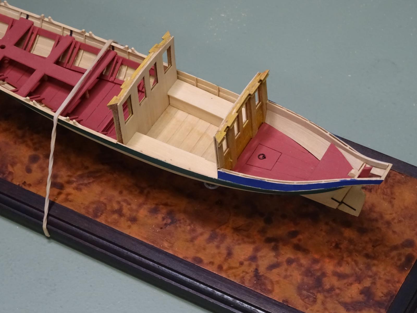
Some progress while I wait for various 'gilding' materials to arrive. The coach benches are made and installed. For the moment the forward and aft coach bulkheads are temporarily slotted into position and still removable. The plan of the coach indicates a locker lid aft. The benches were cushioned for the benefit of the Lord Commissioners' backsides, so these are next. I'll model them based on the ones seen in Prince Frederick's barge

- 641 replies
-
- 39
-
-
- greenwich hospital
- barge
- (and 1 more)
-
Jud: your illustrations appear to show the aft tiller line crossing over the chimney area and so would get cooked.
-
Pat: I used a paintbrush to remove the finish after flooding and softening the paint.
- 641 replies
-
- 5
-
-
- greenwich hospital
- barge
- (and 1 more)
-
Love the tooling and jigs, Gerald! How did you cut out the floor blanks?
- 281 replies
-
- 2
-
-
- falls of clyde
- tanker
- (and 2 more)
-
Nice progress. Is that an iron spike lying there? You really shouldn't use ferrous metal on your model!
-
Cutter Cheerful 1806 by rafine - FINISHED
druxey replied to rafine's topic in - Build logs for subjects built 1801 - 1850
Those belayed lines look terrific, Bob.- 525 replies
-
- 3
-
-
- cheerful
- Syren Ship Model Company
- (and 1 more)
-
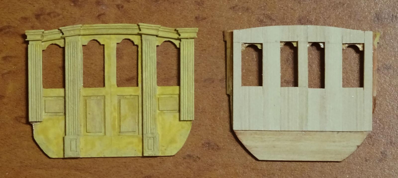
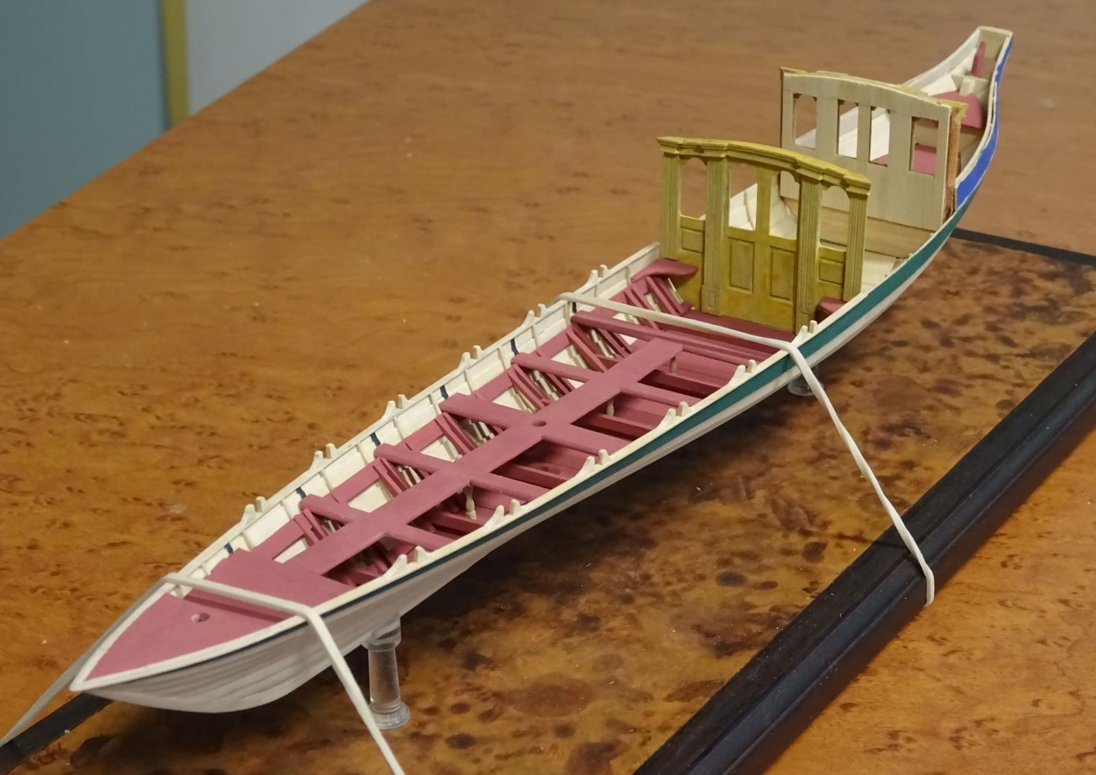
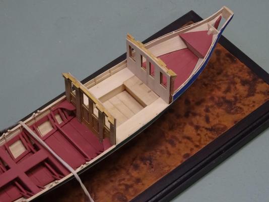
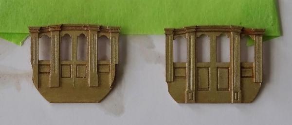
Thanks for the tips and support, everyone. It is much appreciated. I will be experimenting with different 'gilt' finishes over the next few days. The first photograph shows the ends finished in gold paint. This was unacceptable, as previously mentioned. The second picture shows the inner side of one end piece and the other stripped of finish. There is a channel running across the lights between the layers which will enable me to slide the frames for the lights and glazing in after I finish the outer sides. The third photograph shows the ends of the coach temporarily in place. After the seating is in place the ends will be permanently installed and the sides constructed to a sliding fit. Next be to constructed will be the seating inside the coach.


- 641 replies
-
- 29
-
-
- greenwich hospital
- barge
- (and 1 more)
-
Thanks for all these ideas, everyone. I'll try them out. I seem to recall using Buff 'n' Rub years ago on some picture frames. The low sheen it produced may be exactly what I'm after.
- 641 replies
-
- 4
-
-
- greenwich hospital
- barge
- (and 1 more)
-
Well, no photos this time. I've been struggling with gilded finish for the coach. I first tried Humbrol gold paint. The look was too coppery red, 'grainy' and glossy. I stripped this off and sprayed using a yellower gold lacquer. Still far too shiny and grainy - it does not look right at this scale. I've just stripped this off using acetone (ugh!) in a well ventilated garage. I will experiment further. Gold leaf was one possibility, but it will reflect and magnify any tiny surface defect or dust mote. So... back to the workbench.
- 641 replies
-
- 6
-
-
- greenwich hospital
- barge
- (and 1 more)
-
Just catching up, Bill. Good on you to do a re-work. That method of decking looked lovely while it lasted, though!
- 382 replies
-
- 1
-
-
- sovereign of the seas
- carving
- (and 1 more)
-
Consider dye or paint when you make the wales, Mike. Ebony is a b*gg*r from every point of view, as others have mentioned.
- 969 replies
-
- 6
-
-
- hahn
- oliver cromwell
- (and 1 more)
-
Thank you, gentlemen, for your kind remarks. Dan: I'm basing my ideas on the Prince Frederick's barge in the NMM. This has glazed sash lights and ornamental drapes in the corners of the coach.
- 641 replies
-
- 6
-
-
- greenwich hospital
- barge
- (and 1 more)
-
Much detail, Phil? Nah, I don't think so. Thanks for the compliments, Jim and E&T.
- 641 replies
-
- 5
-
-
- greenwich hospital
- barge
- (and 1 more)
-
A 4 pounder would have been usually 5' 6" long. Simply scale down the pattern of the 18 pounder and you'll be close enough.
-
In earlier ships, when planking was sawn by hand, average planks were 24' 0" to 28' 0" in length.
-
Joel has this right. There was a brilliant analysis of the slack/tight line tension and methods of overcoming this by John Harland some years ago in Mariners Mirror. The sweep was the first of these methods.
-
With this sort of hull form the wing transom is usually located at about the lower edge of the main wale aft. Based on the original draught, this coincides with the uppermost transom shown in the sectional view.
- 525 replies
-
- 5
-
-
- anchor hoy
- hoy
- (and 1 more)
-
Cutter Cheerful 1806 by rafine - FINISHED
druxey replied to rafine's topic in - Build logs for subjects built 1801 - 1850
Looking terrific! Not much more to do before she's complete.- 525 replies
-
- 4
-
-
- cheerful
- Syren Ship Model Company
- (and 1 more)
-
I'm always hesitant to take anything in the AOTS series as gospel truth. Perhaps building a mock-up of the presumed arrangement might shed some light on things.
-
Nice to see your return, E&T. I was beginning to wonder what had become of you and your model. Super result with the steering apparatus - particularly as you did this without a lathe!
- 346 replies
-
- 4
-
-
- terror
- polar exploration
- (and 2 more)
-
This is normal. Your woods for the keel and false keel are of different species and absorb/give off moisture at different rates. You need to secure the assembly to your building board. As the build progresses, things will stabilize.
-
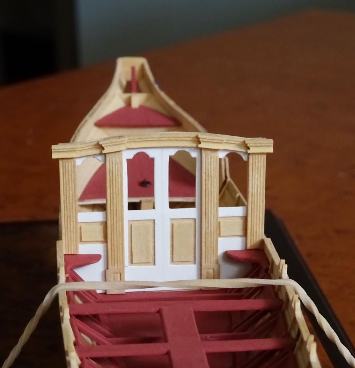
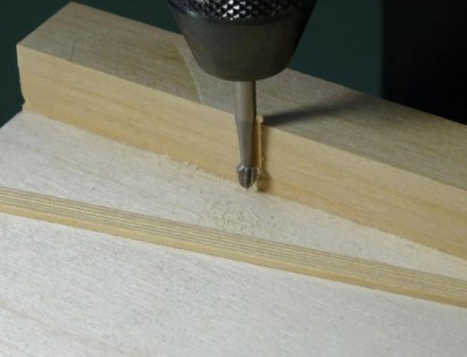
For the coachwork there are numerous repetitive ornamental mouldings. The first of these to produce is a five-reeded column. This is ⅛" wide, so it was tricky to work. I used a micro-milling cutter (Proxxon) on my mill using an x-y table to incrementally cut reeds into the stock. Also required were columnar capitals. Again, two different micro-milling cutters were used. One was a flat-bottomed cutter, the other a very small ball cutter. These produced a fair imitation of the design. The millwork is gradually being built up on the pattern piece. The pattern will be integrated into the coach, as the assembly will be painted when completed. The outer corners still need to be bevelled. Each column consists of three pieces. The reeds are stopped; that is to say, they do not extend the whole length of the column. Plain pieces of stock are grafted on the top and bottom to produce the effect of stopped reeding. In addition, there are small fielded panels in the column bases. These were cut in using a scalpel and a micro chisel. The panels in the doors and on either side were added using stock a scale ⅜" thick.

- 641 replies
-
- 47
-
-
- greenwich hospital
- barge
- (and 1 more)