druxey
-
Posts
13,359 -
Joined
-
Last visited
Content Type
Profiles
Forums
Gallery
Events
Everything posted by druxey
-

Stepping the mast with a plum bob...two questions.
druxey replied to HardeeHarHar's topic in Masting, rigging and sails
While rigging, you can fine-tune the rake (if any) and plumb of the masts. -
Are you sure that those are the broad planks and not the sheer planks? They look much too long.
-
The problem is that the rig of a New Testament era Alexandrian grain ship was very different from an 18th century man of war! A semi-swamped boat, even a small one, would have considerable weight. How this was wrestled aboard (in a storm, yet!) would be hard to imagine. An attempt lower it, once bailed, can be imagined with a pair of lines, presumably with some kind of block and tackle that were then cut away.
-
Make sure that the garboards just overlap the bottom.
-
Welcome aboard, Tyler. You will find plenty of resources on this site. There are tutorials on planking, for instance. (More > Planking techniques) Check out other build logs and then start one of your own.
-
Scale rose lashings! Whatever next? Amazing.
-
"Unbleached titanium" is simply a marketing name. It was first produced accidentally. A batch of titanium white was slightly contaminated with yellow ochre. Rather than throw it all out, the colorist simply labelled it 'unbeached' and it sold well! So it is now regularly available.
-
!!!!! is the only comment I can make to those photos. A builder's style model at that scale today is most unusual.
-
What is a year or so between posts, Clare? Seriously, nice to see you and Wolf back. I like your technique on the steering spokes. Looks good at small scale.
-
Yes, those are for the stretchers, as Chuck has said. The double set of wiggly lines are a carriages for a small set of steps which presumably turn slightly.
-
A great recovery and well deserved recognition, Jake!
-
Instead of tallow-based white stuff, a pitch-based black compound was used on some ships instead.
-
I suspect that the 'only to the waterline' version was for new ships on the ways. It would be far easier to paint the white stuff using the lower edge of the wale as a guide later on. Also, there was 'black stuff'....
-
Look at contemporary paintings: https://www.rmg.co.uk/collections/objects/rmgc-object-11926 https://www.rmg.co.uk/collections/objects/rmgc-object-12537 https://www.rmg.co.uk/collections/objects/rmgc-object-15235 https://www.rmg.co.uk/collections/objects/rmgc-object-12551 Then take your pick!
-
HMS EURYALUS by Matiz - FINISHED - scale 1:56
druxey replied to matiz's topic in - Build logs for subjects built 1801 - 1850
And do those rollers actually roll? Terrific! -
It takes a little time to learn how to coax wood into the shape that you want. Obviously you are learning fast! And we all need to use a little rubbing alcohol from time to time, no matter how many years we've been at it.
- 62 replies
-
- 2
-

-
- Muscongus Bay Lobster Smack
- Model Shipways
- (and 1 more)
-
Good progress! Had you considered using a drawplate for forming treenails?
-
Nice to see some progress, however incremental, Marc. When my daughter was young, no model-making occurred for ten years. You are doing much better than that.
- 2,699 replies
-
- 4
-

-
-
- heller
- soleil royal
- (and 9 more)
-
Chacun à son goût! - Each to their own taste. The individual style of different builders is what makes things interesting. It would be dull indeed if we all built in exactly the same way with the same amount of detail - or lack of it. P.S. Decks were never treenailed to my knowledge, but nailed and plugged, which was almost invisible. However, some builders like to show fastenings. I'm not defending the practice, but if folk like it, let 'em do it!
-
I'm so sorry that you were scammed, Aleksandr. I've tried milling such moldings and still prefer the control of using a scraper that has been shaped from a scrap piece of hacksaw blade. Using a mill sometimes 'eats' the work as one feeds it through! Perhaps this was a lucky accident for you after all.
-
Glad to read that all is going well, Keith. A friend's Admiral recently had cataracts removed. She was quite indignant at the sight of her wrinkles in the mirror. She is 86.
-
Those smaller splices are ridiculously good....
-
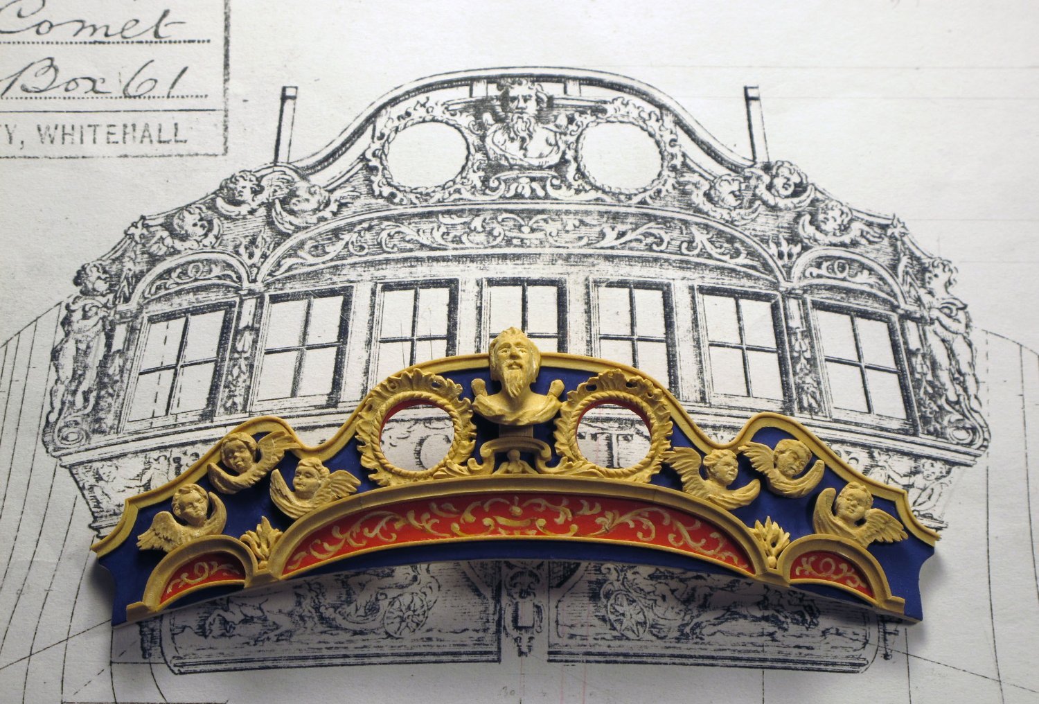
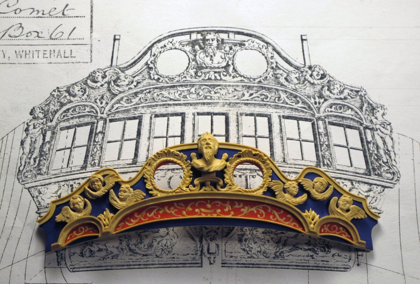
Certainly is a very wide lion!