catopower
-
Posts
1,915 -
Joined
-
Last visited
Content Type
Profiles
Forums
Gallery
Events
Everything posted by catopower
-
mkmossop, nice job painting that emblem. I think that can be easier than iron on because after you do your sewing, you've already got the right colors matched to do your touchup. As JerryTodd points out sewing will be a little out of scale. But then, the printing is probably equally out of scale and I think the sewing stitches will look better. I personally like a tight stitch as it forms a solid line, like the seam of the cloth itself. Use a fine thread. When I have sewn, I'd sewn to the edge of the sail itself. I think I was initially sewing on past it, but then I had to take a needle and pull out the excess stitching back to the edge of the sail. I agree that adding the reef band and reinforcements can look really nice. It's at that point that I personally glue the fabric and do not sew. The extra layer of fabric is enough to give definition to the feature. Same with the bolt rope. The glued bolt rope looks nice, but a sewn bolt rope tends to stand out a lot more than a glued one. With sails, I think it becomes something of a matter of personal taste and use of artistic license. Clare
-
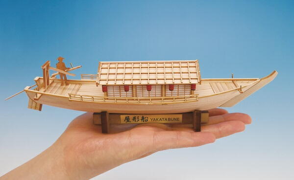
 Hi Richard, The Mini-Yakatabune looks like a really nice kit. Personally, I haven't put a finish on these. I don't worry about dust because I put them into cases, and Hinoki is also naturally mildew resistant. If you check with Bob Riddoch, I think he's using some wipe-on poly on his Higakki Kaisen, giving the wood a nice darker color and sealing it too. Anyway, you really only get the smell of the wood when it's wet or freshly cut, so the completed model won't have that nice smell. If your daughter really loves the scent, you might just get her a small bottle of Hinoki Oil or some Hinoki Soap. Now that I say that, I may just have to get some myself! Clare
- 106 replies
-
- 6
-

-
- Japanese boat
- Wasen
- (and 2 more)
-
Hi Richard, Glad you like the saw. I feel a bit responsible for Kazunori at Zootoyz having ordered a stock of them after I asked him about carrying the product. They weren't selling very well at first and I expect it was mostly because nobody knew he had them. So, I had to "spread the gospel." The towel is something he recently started doing, including small gifts with each order. It's a nice touch. I got a towel with The Great Wave painting on it. Maybe they'll end up being like trading cards "Collect all 10!" Druxey, I love that you know the name of the artist and the actor in that painting. You never cease to amaze me! Clare
-
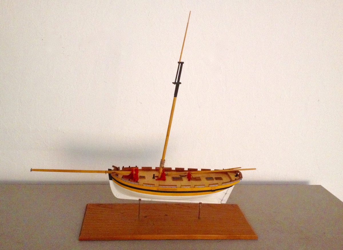
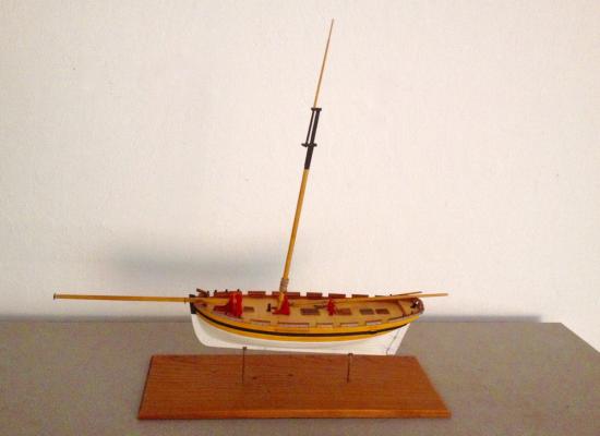
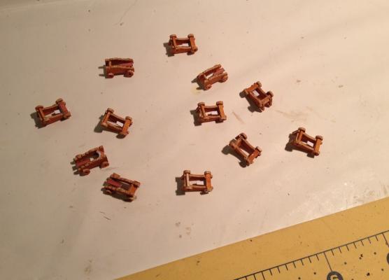
I realized that I hadn't posted any updates on HMS Alert (HM Cutter Alert) in some time. Also, I notice that I haven't posted an overall shot of the project. Time to remedy the situation. The project is still one of those "in the background" projects, as I've got other projects that have a much higher priority. I only work on the model in between other work, so it's slow progress. Most recent work on it includes working on the yards, boom and gaff. But, the big project was making the gun carriages. There are a dozen in all. Because of large amount of small detail pieces, I'd found that the laser cut add-on detail part set that I used for the gratings also had cannon carriages of about the same size. So, I used those to make mine. I've had to learn how to work with the laser-cut cardboard and still working on figuring out best practices. The laser-cut cardboard is a lot softer than the paper parts I build up using layers of printer paper, which is a lot denser in the end. So far, I've just found I have to be a lot more careful with the cardboard. But, it helps to hit with some CA so that it stiffens up. Makes it easier to cut. Now, I just have to decide what I want to do about the cannon barrels. I rolled them up, but they're so small, I managed to get them a little gluey and spoiled some of the pre-printing on them. I'll probably have to just paint them black. But, each barrel also has a round muzzle pieces and 3 round cascabel pieces. More really tiny round parts! One option has been to, at minimum, turn a master in brass and just cast them. I'd have to do the same with the swivels. Oh wait, I'd better get back to one of those priority projects! :0) In the meantime, here's a view of the model as it sits on my shelf awaiting the next steps... Clare
-
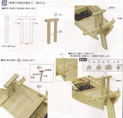
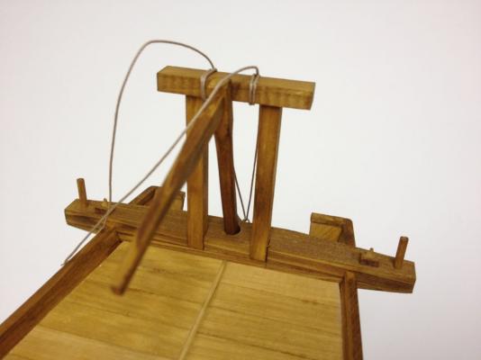
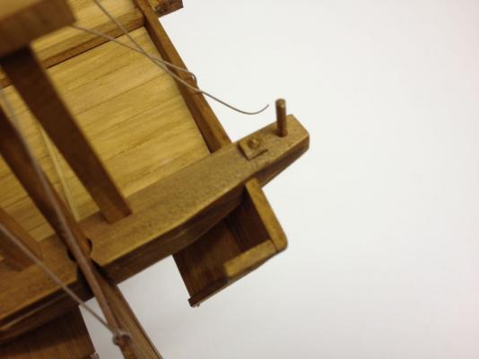
I was going to save Step 20 for next time, but I started to work on the translation to get it out of the way. Now, I might as well post it! 20 Assembly and Installation of the Rudder Support • Assemble the rudder support and attach to the rudder support pedestal. Center the crossbeam on the support posts. • Attach thin rigging line to rudder and wrap line around the rudder support crossbeam. Tie off using a clove hitch. • Install part 9C as per the cutaway view and full size plans. Note that a length of small rigging line needs to be secured to part 9C in such away that it forms a loop a maximum of 38mm long. This actually brings me up-to-date with where I'm at on the model today. Next steps involve the construction of the deck house and its details. Clare
- 106 replies
-
- 8
-
-
- Japanese boat
- Wasen
- (and 2 more)
-
Thanks George. Had to slow down a bit due to meetings and other commitments. Also have other projects people are waiting on. But, we're now on page 10 of a 16-page instruction book, so I've got to keep on moving. Also, I've got some ideas for the next Japanese boats display and planning to make some connections regarding that. I will need this model for that display too, so there's plenty of incentive to keep working on the Yakatabune. Step 19 is another pretty short one, now dealing with some of the stern assembly: 19 Assembly and Installation of the Rudder and Oar Receiver • Insert the rudder from the top of the rudder pedestal Inset: Assembling the Oar Receiver Make 2 pieces Cut piece of dowel, part #23, 4mm long Trim to a cone shape You can see the details of these parts in the photos of my last post. Clare
- 106 replies
-
- 3
-
-
- Japanese boat
- Wasen
- (and 2 more)
-
This may seem an even sillier questions, but why are you using "Pewter Black" on Brass, and expecting it to work? Maybe I missed some of the discussions on Jax and maybe it's supposed to work well on brass? Clare
-
She's looking beautiful, Bob! Nice job on the lattice work. Did you ever handle a more delicate piece of laser-cut wood? I was never so worried about breaking a wooden part before... Clare
- 196 replies
-
- 4
-
-
- higaki kaisen
- woody joe
- (and 1 more)
-
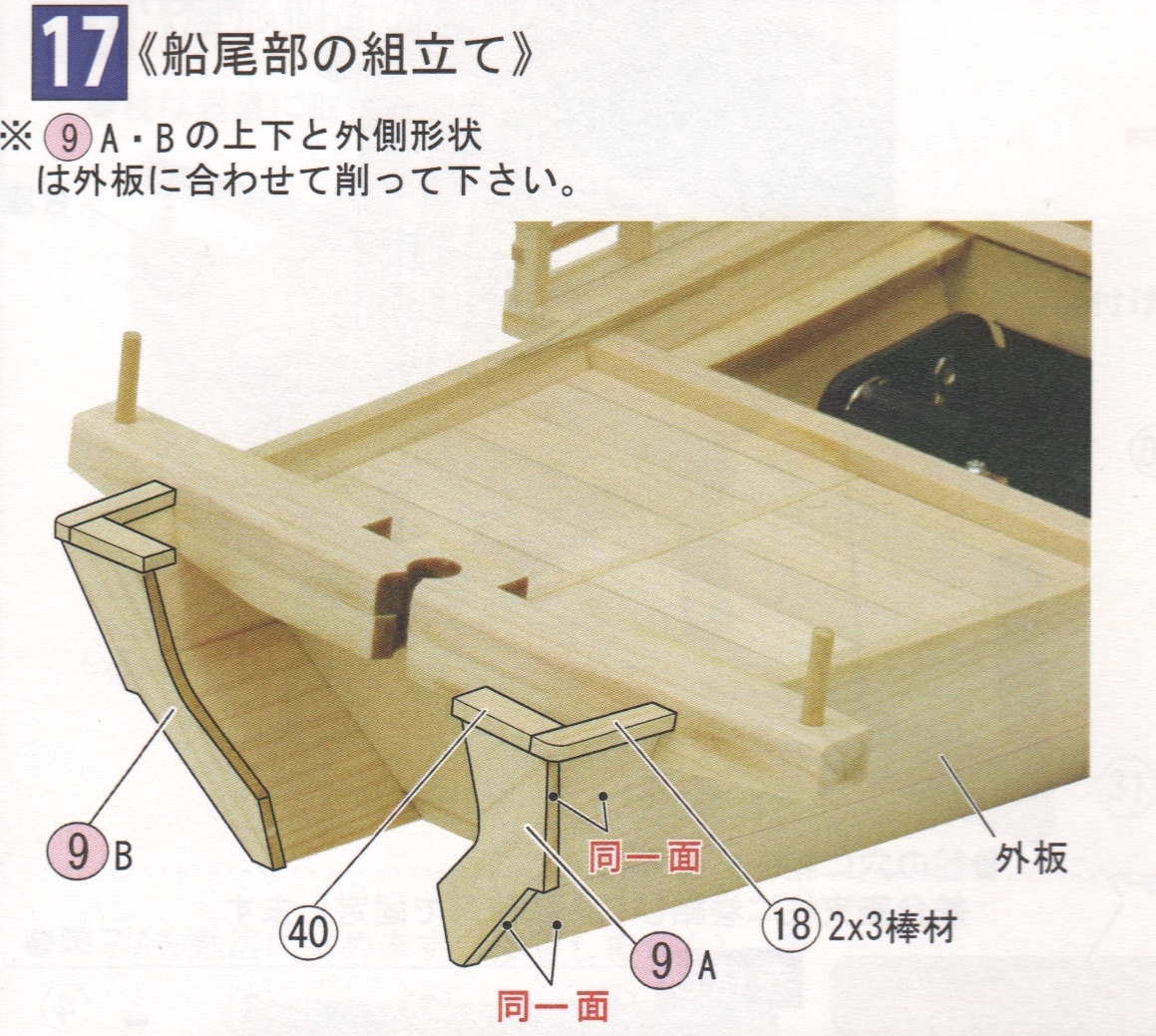
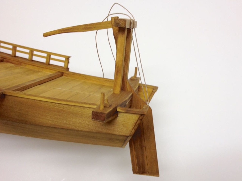
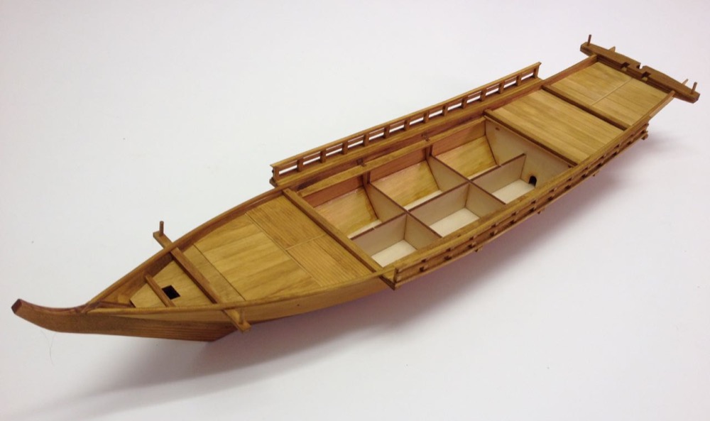
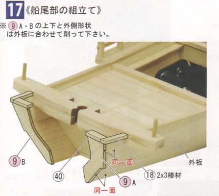
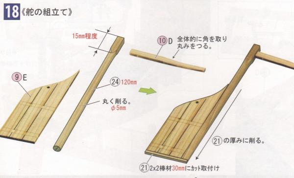
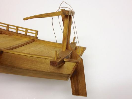
Kind of moving right along here, there are four steps remaining to complete the basic hull. These are mostly pretty quick and involve finishing the stern, building the rudder, adding oar mounts, and finally, adding the gallows-like rudder support and hanging the rudder from it. These were very quick steps and, unfortunately, I managed to get through them without taking any photos until after much of it was done. Here is the next step: 17 Stern Assembly • Fit parts 9A and 9B so that they fit flush with the upper and lower planking While not mentioned specifically in the instructions, you should install strips 18 and 40 so that the inside edges are flush with the hull planks, like the rail in Step 14. Round the corners Not much to add here. It's a quick step. 18 Rudder Assembly There are only notes listed on the plans. The rudder post is made from a length of part 24. 15mm of the top end is square stock, while the remainders is first rounded. The rudder post is then tapered flat so that at the bottom end, the thickness exactly matches that of the rudder. Not shown here is a black-and-white diagram showing the cross section of the rudder post at various points. The tiller is a rectangular cross-section where it attaches to the rudder. About half way down it's length, the cross section becomes more circular. Note that I felt that the rudder seemed rather large for a small river craft. Steering is mostly accomplished by the boatman at the stern who is propelling the boat using a sculling oar. Other boatmen might also be pushing off a shallow lakebed or riverbed with a long bamboo pole. So, the rudder seems a bit extraneous. I went ahead and remove the trailing panel of the rudder, which is about 1/3 of it. The following photos were taken near the end of step 20. You can see the rudder support and other details in place. The rigging line shown in the photos is part of the rudder lifting gear. It's tied into place but just hasn't been trimmed yet. Clare
- 106 replies
-
- 8
-
-
- Japanese boat
- Wasen
- (and 2 more)
-
Thanks for the comments Jason. I'll be posting the next update some time today. Clare
- 106 replies
-
- 2
-
-
- Japanese boat
- Wasen
- (and 2 more)
-
Brings back fond memories of studying and tutoring algebra, but it's not something you need to know about in terms of ship modeling. The "modeling" the narrator is speaking about is Mathematical Modeling, not physical construction of hulls. These days, I think the only time polynomial mathematics come in to play is all "under the hood" when using CAD and illustration software. The computers use the math, not the CAD operators or the architects. Important stuff, but mostly when developing the computer software. Of course, not really being into CAD myself, maybe someone with more experience on the subject can chime in on that. But, if you enjoy the math, study it. It can be fascinating stuff and great mental exercise. Clare
-
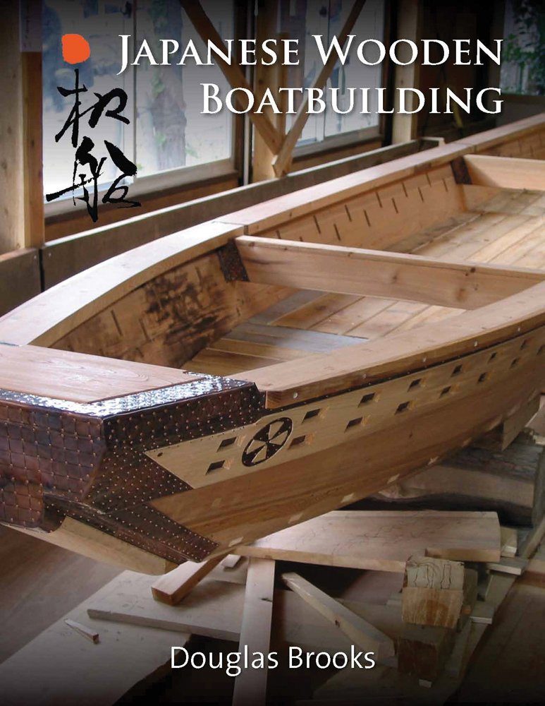
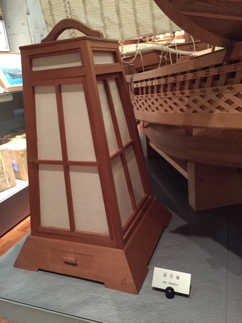
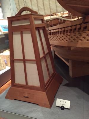
Hi Marc, Seems that you're the second person in Japan to send me that same black & white graphic. Thanks for the images of the paintings showing the hanging lanterns. That did come up and it really does make a lot of sense. Wiring to the ceiling isn't impossible, it just has to be carefully hidden. Or rather, it OUGHT TO BE carefully hidden. The kit doesn't tell you to do that. I know there were floor lanterns on ships. Someone sent me a photo from a museum. Looks like a Higaki Kaisen in the background. But, this one seems kind of big for the Yakatabune. I'm still going to be giving this some thought. Personally, I think the boxy-shaped floor lantern will be easier to make and light than the round hanging lantern. By the way, I got a neat surprise in the mail today from Japan. Woody Joe recently released a third wasen mini-kit, a mini-Yakatabune. This was sent to me by my friend at Zootoyz, which sells these kits internationally (and I highly recommend his simple online shop). This is a simple mini-kit that lists for 5500¥. Build time is supposed to be about 8 hours. For 18000¥, the larger Woody Joe kit is a better buy. But, the mini-kit seems nice if you want something small or something quick to build. I'll probably make a more elaborate post in the thread I started elsewhere on Woody Joe kits on MSW. Right now, I'm mostly distracted by a brand new book release by boat builder Douglas Brooks. His book will be available through normal online channels, but you can buy a signed copy now direct from him through his website Douglasbrooksboatbuilding.com. Brooks is an American boatbuilder who, in an attempt to preserve the disappearing art, studied Japanese traditional boatbuilding through five apprenticeships with master Japanese craftsmen, where he was their final and in most cases, their only apprentice. He is scheduled to talk about the subject at the NRG conference in Mystic, CT, this Fall. If you prefer to wait, I'm sure you can get your signed copy from him there. Clare

- 106 replies
-
- 7
-
-
- Japanese boat
- Wasen
- (and 2 more)
-
Hey George, Ken, Buck, thanks for the nice comments! Buck, I had to look that word up, I don't actually know very much Japanese. But, I think you're right, about the stand and all. I'll be playing around a bit with the lanterns. I think it's harder to figure out what would have been in use than it will be to actually make them. I'm looking forward to that part. Been away on business most of this week and have events last weekend and not much time to do fun stuff, so no updates until later this weekend. But, stay tuned! Clare
- 106 replies
-
- 4
-
-
- Japanese boat
- Wasen
- (and 2 more)
-
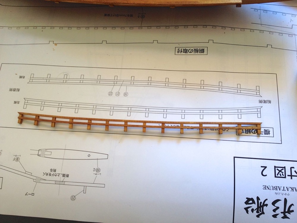
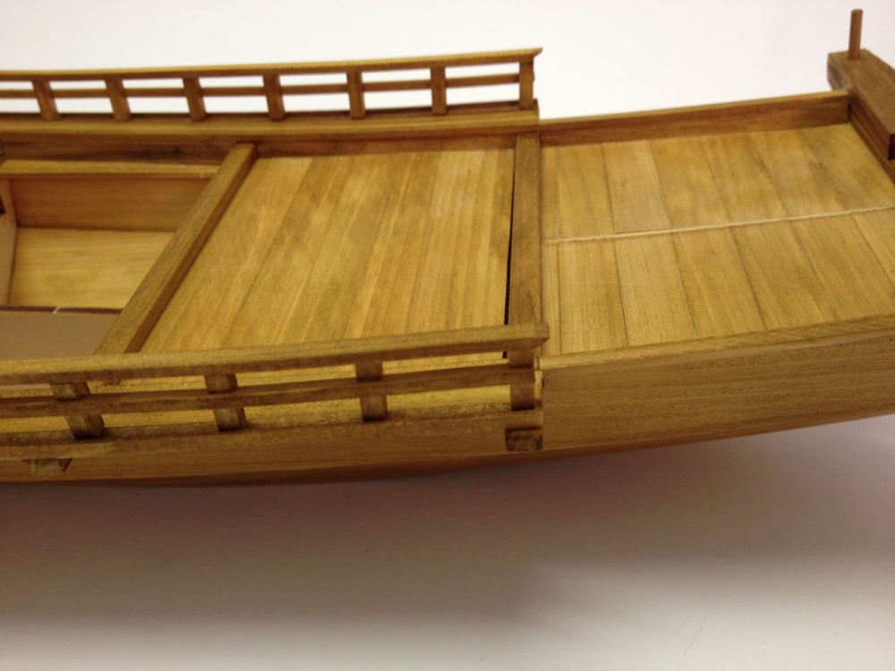
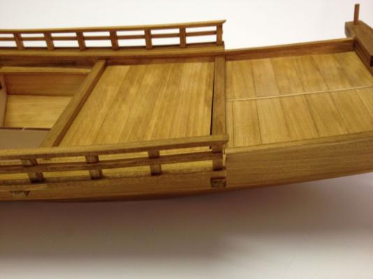
Glad to be of some help, Bob. Heck, your build helped inspire me many times, so I'm glad to return the favor! Well, the last couple of days, my brain has just been all fuzzy. I'm not in a ship modeling rut, just a general rut. Looking forward to our local gathering of forum ship modelers in Vallejo tomorrow. Maybe that will wake up my brain a little. Am managing this post, though, so I guess I'm not totally fried... Okay, so about that walkway platform. The kit instructions translate this to either railing or parapet. I'll just call it railing. Here's the translation I worked out from the instructions for this step: Step 15 Installation of Railing, Part 1•Refer to the plans in the installation of the walkway. Cut (planks ends) flush with the edge of the beams Trim off the protruding ends of the beams This step requires a little soaking and bending of wood strips. Again, definitely wet the wood thoroughly before trying to bend it. Bends very nicely when wet, no heat required. Walkway planks added. Closeup of the walkway planks. You can see the beam sticking out a little at lower left that will need to get trimmed flush with the planking. Also, I think you can make out that the outer planks here are the L-shaped ones. This creates a little lip against which the posts of the side railing fits against. Carrying on to complete the rail installation... Step 16 Installation of Railing, Part 2• Please assemble the handrails according the full size diagrams. Mount the railing to fit up against the lip With pre-cut parts for the rail stanchions, this step is pretty simple. It just requires a little pre-bending of the rails themselves, and the stanchions should be kept vertical, so they aren't all perpendicular to the rails themselves. Rails assembled according to the full-size plan sheets The stanchions aren't pegged in, just glued. I'm using Titebond, so I want to clamp them firmly in place until glue sets Both rails now in place Closeup of the rail detail. It's at this point that I really started to look at this model as a really nice example of a very Japanese boat. The concept of the pleasure boats with several people out on the water for an evening and watching fireworks over the river on a warm summer night is a very charming image. In a previous post, I mentioned Japanese lanterns. Then, the person who suggested them had a though about how maybe these standing floor lanterns might not have been used by a boat that might rock and they might tip over, which I really did wonder about. Then, I spoke with my Japanese music teacher (I have been a student of the Japanese 3-stringed lute called a "Shamisen" for about 10 years now), who used to live in Asakusa, which is a part of Tokyo with a traditional Edo period theme (well, that and lots of old style shopping). As far as Japanese people go, my teacher is pretty connected with traditional culture and she's been interested in my traditional Japanese boats, but especially the Yakatabune. I think it's a real cultural symbol of "the good life" and very important to many people when they think about it. Anyway, I mentioned the lantern to her and about the possibility that they might have had to use hanging lanterns because it was in a boat. She pretty confidently dismissed that idea. I guess the idea is that floor lanterns were classy and the hanging ones, not so much, except outdoors. Probably the boatmen worked pretty hard to not rock the boat. Thinking about it, it's not like there were any power vessels at the time to create big wakes, so not much reason for a decent sized boat to rock. So, I'm sticking with the floor lanterns idea, which I'm really glad about. Clare


- 106 replies
-
- 10
-
-
- Japanese boat
- Wasen
- (and 2 more)
-
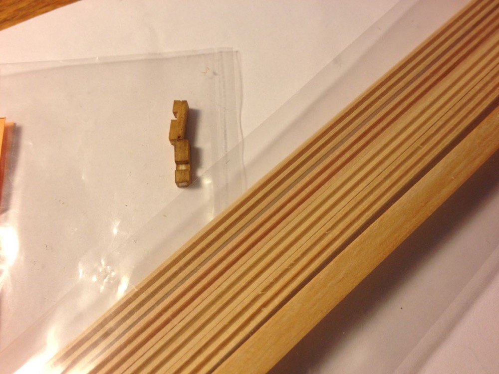
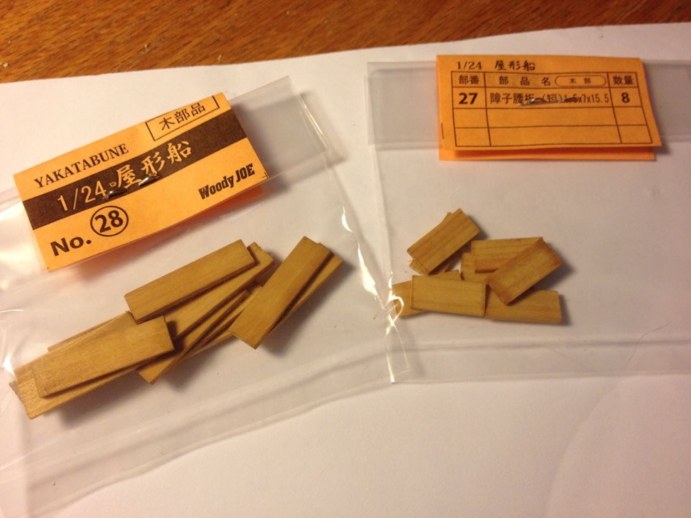
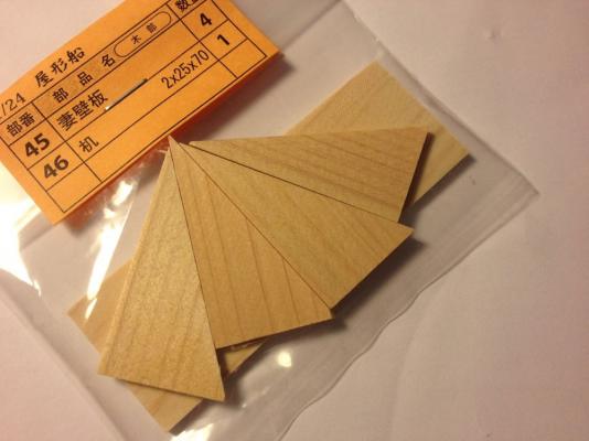
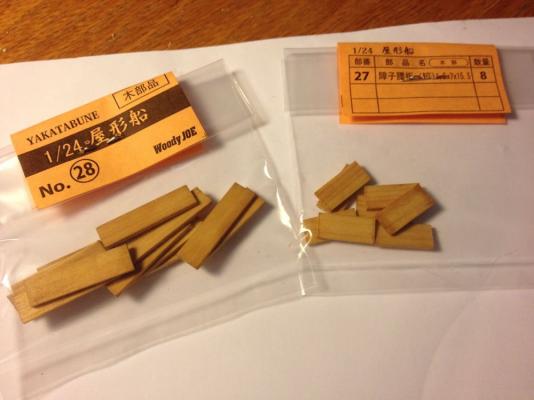
The Yakatabune has a walkway platform on either side of the deck house, allowing the boatmen to travel more easily between the bow and stern ends of the boat. In building this, I'm noticing the use of parts which aren't laser cut and aren't simply cut strips of wood. There is a strip, Part 19, that has an L-shaped cross section. So, this is a milled piece of wood. In fact, as I look through this kit, there are several parts that are milled so that they are notched or slotted. This is kind of a carry-over from the older Woody Joe kits, before they had laser cut parts. But, it's kind of nice. On a Western kit, I think one would be expected to make an L-shaped cross section by gluing together to strips to for the L. Slotted pieces I expect would have to be built up similarly. But, not only are there these parts, but also a fair number of pre-cut parts as well. I also notice some parts are simply pre-cut, again not by laser. It doesn't affect the build in any way, but it's just interesting to see, since we don't often see this in American or European kits. Some milled parts. Pre-cut parts And more pre-cut parts Actually, looking back, I realize the parts for the stand were milled and machine cut too. But, the parts are perfectly cut parts, clearly it's not like the old days of die-cutting. I'm guessing they are actually CNC milled. Woody Joe does make some other wood products including castle and temple and small structure kits, plus Japanese flower holder kits and I don't know how much other stuff. Clare

- 106 replies
-
- 9
-
-
- Japanese boat
- Wasen
- (and 2 more)
-
Well, that was easy. All the images and links were there, I just had to resubmit the post. Hi George, that's my hope. The instructions for this kit are short enough to be able to detail them here – We're nearly half way through the build. More soon! Clare
- 106 replies
-
- 4
-
-
- Japanese boat
- Wasen
- (and 2 more)
-
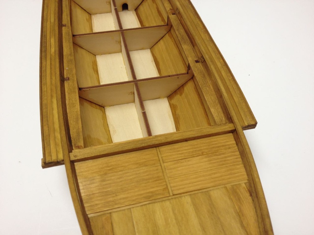
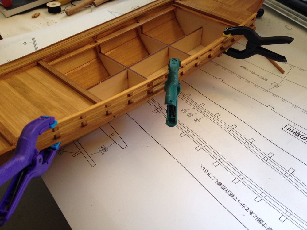
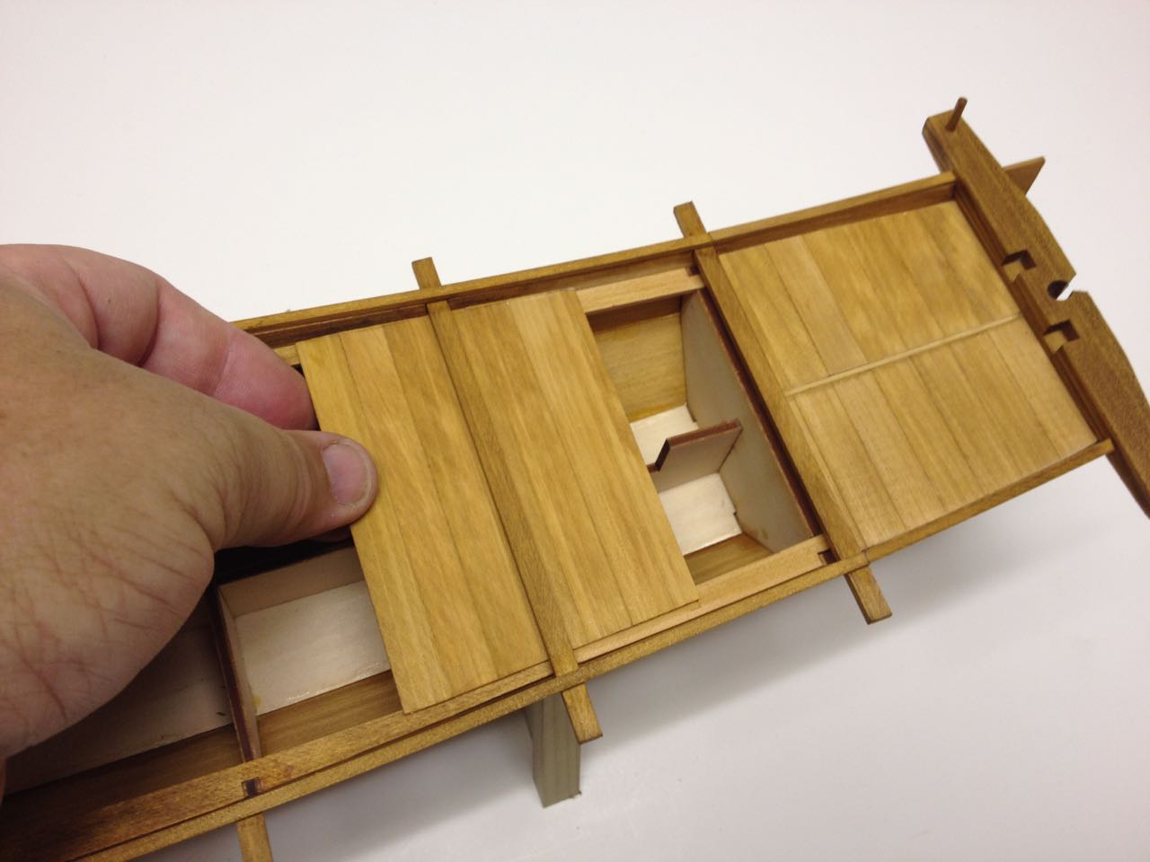
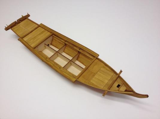
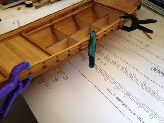
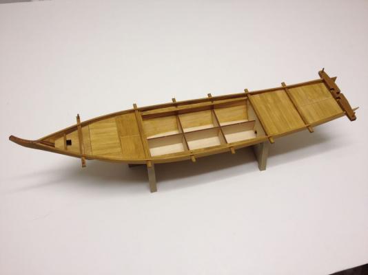
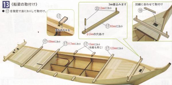
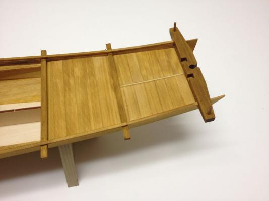
Now, getting back to boat construction. The deck planking is complete since the center section is the area for the deck house. The next step is to cut and fit the beams. On a real traditional Japanese boat, the beams would be mortised into place. On the model, they're not really structural members and just glue in place in the laser cut notches of the upper planks. If the upper planks were mounted too low, the beams wouldn't fit properly as there is little clearance for them once the deck planks are installed. The beams are among the included strip wood supply, so they have to be cut to length. This was a good opportunity for me to use the Japanese hobby saw I got from Zootoys. The saw isn't cheap, but if you're buying a kit from Japan, it shouldn't add much to the shipping cost since it's so light. This is the first Japanese saw I've owned and it is a treat to use. Unlike Western saws, Japanese saws cut on the pulling stroke. This keeps the cut very straight and allows the saw to be very thin. This is, in fact, the thinnest hobby saw I've ever seen at only 0.1mm thick. All in all, the cuts are very straight, very quick, and very clean. This photo may make the saw look a lot bigger than it really is. It's just under 8" long and is very light weight. Anyway, cutting and fitting the beams was very simple. The short beams were a bit more of a challenge since the inside edge is sanded flush. Below, you can see how the battery cover section of the deck is left so that it can slide in and out of place. I recommend removing this section while working on steps 13 and 14 to better avoid accidentally gluing it into place. Note that all the photos show the caprail in place. That's actually step 14. Basically, full length strips are shaped to fit at the stem, but the won't be long enough to reach the full length of the boat. At the aft end then, short pieces are put into place. The caprail fits so that the inner edge is flush with the hull planking. This is a very straightforward part of the build. Roughly Translated Text (some of this required a little more interpretation to make sense): Step 13 Installation of Beams • Cut and install 17 to dimensions shown and install. Short beams should be mounted flush with the inside of the hull planking Cut a part 18 to fit the laser cut area at the bow deck as illustrated. Fit of short beams on starboard side is the same as on the port side. One line I can't quite translate exactly, but can only interpret. On Bing Translate it comes out as: "3 mm difference between narrow the scope" On Google it comes out as: "3 mm Masu Plug" What do either of these mean? This is a straight forward step where a 2mm hole is drilled in either end of a beam and a 12mm long dowel piece is fit into them. The exact positions can be viewed on the plans. The only thing that I can figure about the “3 mm” reference is that 3 mm of the dowels will fit into the beam. I should point out that Bing seems to translate better than Google – At least for Japanese text. The above text makes more sense with the instructions illustrations. Again, with permission from Woody Joe. Step 14 Installation of Deck Edge (Caprail) Bend pieces to shape of hull. Please add short sections at stern. (Japanese instructions are quite polite and often say "please") Align inside edges of rail to inside of hull. The model is looking more like a traditional Japanese boat now and I'm really finding that I am enjoying this build perhaps even more than the last one, which had sails and oars. This one, somehow feels culturally significant, if that makes sense. Clare


- 106 replies
-
- 11
-
-
- Japanese boat
- Wasen
- (and 2 more)
-
David, I agree with CWG that this is not the SeeAdler kit. I don't know what kit it is, if it's a kit at all. The tall lower masts suggests to me that this is probably a 3-masted schooner. You can probably finish it up that way rather quickly and easily. Clare
-
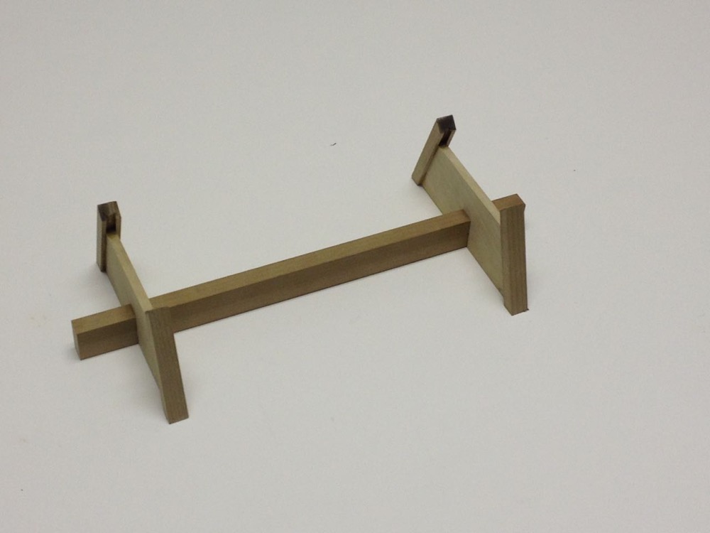
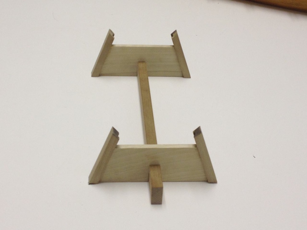
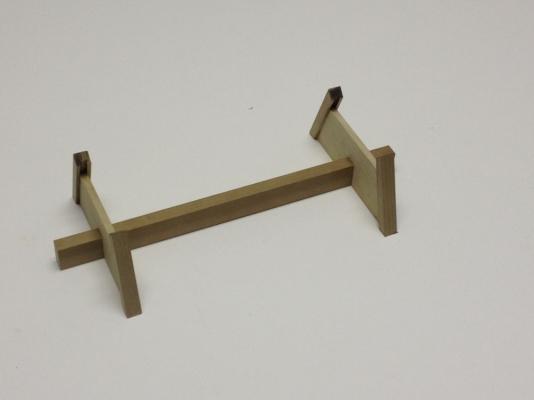
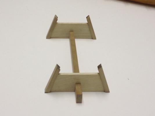
In my last model photo posted, you can catch a glimpse of the stand that is included with the Woody Joe kit. This is a nice feature that is included in all the Woody Joe kits I've owned. The stands are all made of Japanese Magnolia, called "Ho" in Japanese. It's kind of a light grayish brown color with very little grain. It's a somewhat plain looking wood. But maybe that keeps your eye focussed on the model and not the stand. On other models, I've drilled the stand out to add a brass rod that runs into the bottom of the model, helping to keep it from sliding around. I haven't gotten to it yet, but I think I will use a piece of brass tubing in one of the stand pedestals to allow wiring to pass on into the bottom of the model. This step really requires not translation or explanation. I think every ship modeler understands that the top ends of the supports need to be tapered to fit the hull of the model, and the base of the supports need to be trimmed to sit flush with the bottom of the stand. Translated text: 12 Stand Assembly • Stand is assembled to fit the hull. • Trim the hull supports, parts 33, to fit the shape of the bottom of the hull. Then, trim to bottom of the supports to fit flush with the bottom of the stand. Note: See full sized drawings for mounting location of hull on stand. Cut to fit the lower hull planking. Bottom of hull rests on the stand. Cut the bottom of the supports. On the name plate, I decided to try to fill in the text. The plate is a piece of wood and the text is laser-etched into it. The etching is darker than the rest of the wood, but it doesn't stand out all that much. So, I tried to seal the wood with Danish Wood oil. I didn't know if this would actually seal the wood, but it seemed like it should give a couple good coats. After giving it time to dry, I used some black acrylic paint and filled in the etched areas as cleanly as I could. Some paint did get out of the flat surface of the name plate and I had a difficult time cleaning the excess paint off completely. After a couple applications of black paint had dried thoroughly, I lightly sanded the surface of the name plate to take off any smudged paint. This worked well enough, though not as cleanly as I would have liked. People who can read Japanese can probably make out the characters. People who can't read Japanese can't tell what's readable and what's not, so all is probably well! No photos of the nameplate yet. Also, I haven't added the wiring tube or brass rods to the stand yet. I figured I'd wait and give myself time to think the wiring process through. Clare
- 106 replies
-
- 8
-
-
- Japanese boat
- Wasen
- (and 2 more)
-
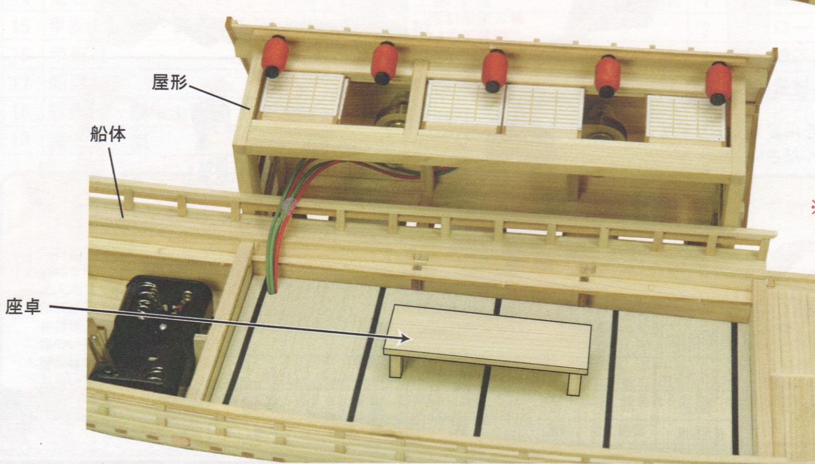
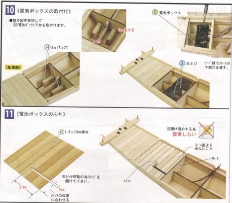
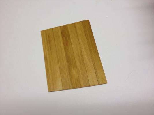
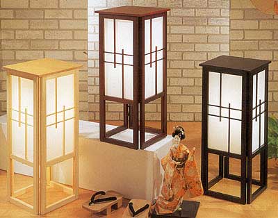
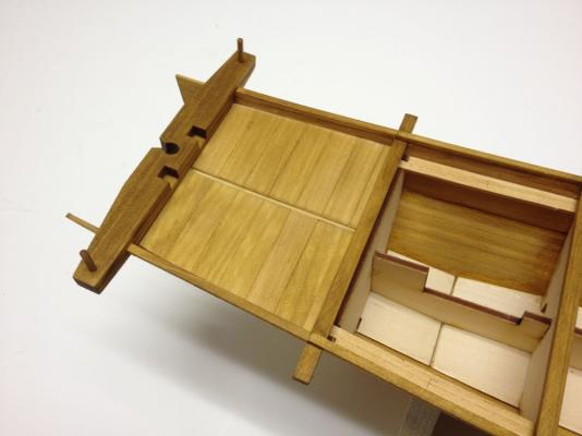
The Yakatabune kit is designed with internal lighting. Kind of separates this model from some of Woody Joe's other models. The lighting is simple and consists of a pair of small incandescent bulbs powered by a pair of AA batteries. I considered a few possibilities with this. One possibility is just to leave the lighting out of it, since the real idea behind building this model is to accompany a couple other models for a bank window display. The lighting wouldn't be noticeable and certainly wouldn't last long on a pair of double-A's. Also, the battery switch is made to stick up out of the deck and I don't like that idea. Another possibility is to use LEDs, light up the interior and make new hanging lanterns outside the deck house with LEDs in them. Problem with that is all the wiring and the fact that I don't necessarily want to light it up like a Christmas tree. The last option I considered is to just replace the bulbs in the model with LEDs, which should give longer life, and not require too much wiring. In all cases where there is lighting, I wouldn't want to go with a battery pack. So, I'll have to do some planning out of the wiring to use an external power source. Steps 10 and 11 mostly deal with the battery pack, so I skipped most of this in my model construction. However, the kit text is roughly as follows: 10 Installing the Battery Box • Referring to full scale drawings, install Part 14 stands for battery box. • Wire leads pass through hole in bottom of frame There are a couple parts labeled • Miscellaneous Part 2, Battery Box • Metal Part 3, Screws This step requires gluing a pair of support blocks to the floor of the boat, running the wire leads forward through the hole in the bulkhead, and screwing the battery box into the support blocks. 11 Installing the Battery Box Lid • Do not glue battery cover in place. This needs to be free to open and close. • Deck/Battery Cover should be long enough to cover the edge of the frame (frame 6). • Cut a slot in the deck 3mm wide and 27mm long to allow movement of the battery switch. You'll need to refer to the position of the switch to make sure the slot in the cover lines up with it properly. You can see here that Woody Joe now puts a nice big icon with a glue bottle crossed by a red "X" to indicate to not glue a part. This was one weak point on their Higaki Kaisen instructions that I wrote to them about. I don't know if I was any influence, but this is a big improvement for those who don't read Japanese AND for those who just don't read instructions very closely! Here's the deck piece that would have served as the battery cover. I'm leaving it removable so I can work on wiring. And here is the battery cover deck in place. It's a bit of a pain trying to slide it out as it's hard to get a grip on the deck without marring it. I'm probably going to glue something to the edge of the cover so that I can get a better grip without causing any damage to the wood. And, now that I think about it, with that battery switch, I'm not sure how that would work. If it's sticking up through the slot, you can't slide the cover out. If you push it into the slot so that you can slide the cover off, how do you reach the switch to pull it back up into place once the cover is back on? Maybe I'm not seeing something here. But, since I'm not installing the battery pack and switch anyway, that's a question I'll leave to another builder. My latest thought is based on a suggestion someone made when I discussed the adding of details to the model. The idea is instead of putting in two ceiling lights, which would not have existed in an Edo period boat, putting in a couple large floor lanterns. These would be box-like structures that would probably sit in the corner of the room to provide light. This avoids having to run wires into the ceiling. This also should make the deck house more easily removable if needed. I can try to make the lanterns and mount LEDs in them quite easily. The resistors for the LEDs can then easily be mounted just underneath the floor. Here's a look ahead in the instructions, so you can see how it's intended to work. The lanterns should be similar to these modern made floor lamps that I found on the Internet. Not sure yet what level of detail I want to go to yet, but I'm developing some ideas. Clare

- 106 replies
-
- 14
-
-
- Japanese boat
- Wasen
- (and 2 more)
-
Thanks Gary. Will be good to meet up with you and the guys on Saturday. I wasn't actually planning to bring the Yakatabune because Kent asked me to bring my HMS Victory and I wanted to keep up to date on that. Also, I brought my completed Hacchoro model last time (or the time before) and this looks pretty much the same right now. Buck, the more models, the better! Right? Clare
- 106 replies
-
- 3
-
-
- Japanese boat
- Wasen
- (and 2 more)
-
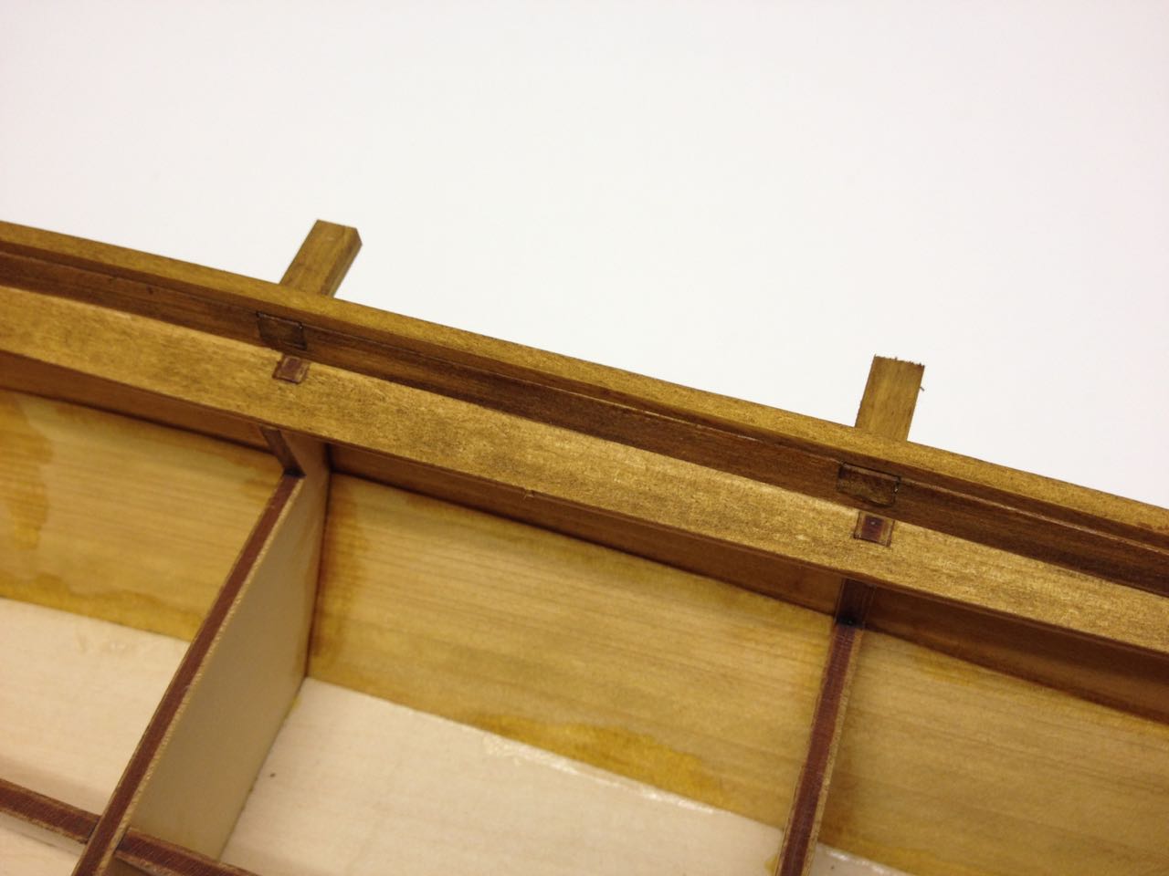
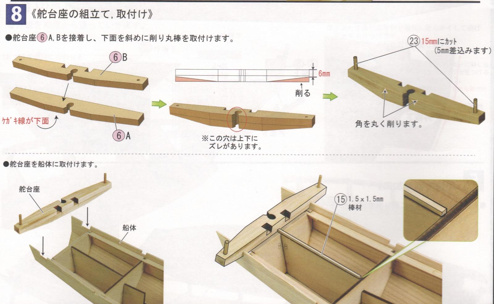
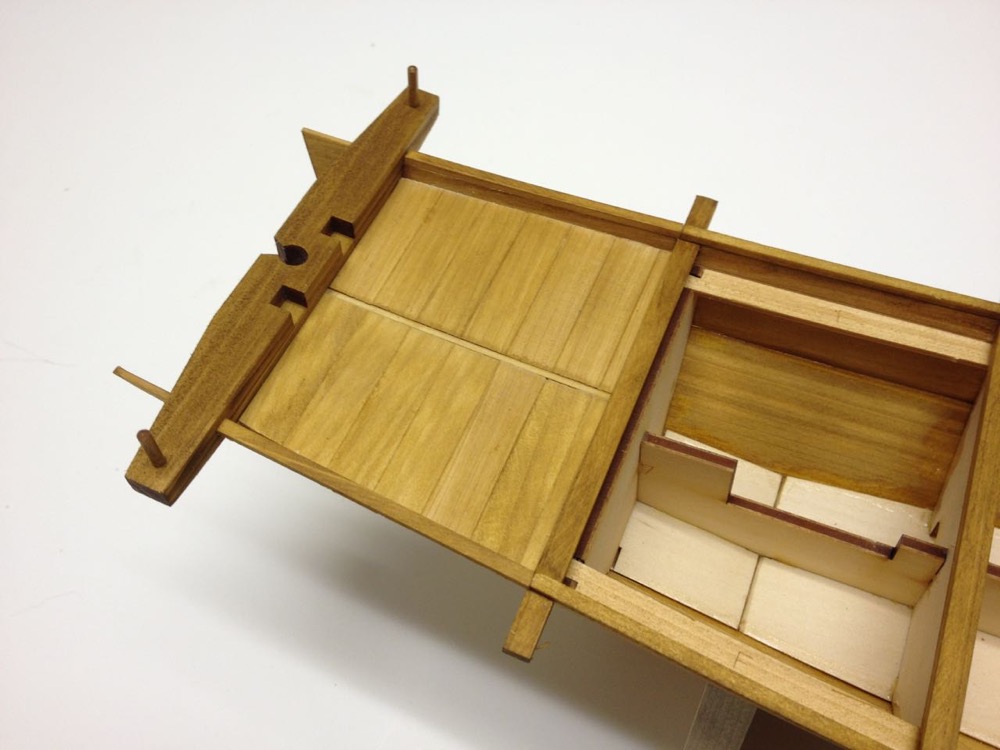
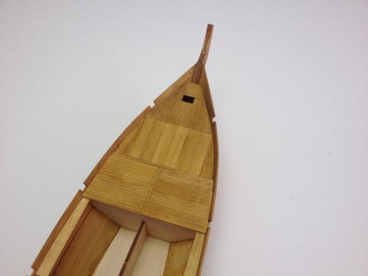
A feature that seems very common to all the traditional Japanese boats I've worked on so far (4 of them) is something called a Kajidaiza (kah-jee-die-zah). This is a heavy beam at the stern which is notched for a rudder. I've seen other Japanese boats that has the beam with no rudder hole, but I don't know if it has the same name. The name apparently translates to "rudder pedestal." There are no gudgeons and pintles on traditional Japanese boats. There is no fixed mounting of the rudder at all. Rather, the rudder is held up in place by ropes. The ropes are also used to raise and lower the rudder as needed. They can be raised when operating in shallow water or when beached, and they can be lowered and even fixed in place to act as a keel. On the Yakatabune, I'm not really sure what purpose the rudder serves. These boats were usually propelled by a single oar or a combination of the oar (sculling oar) and long bamboo poles to push along the shore or shallow bottom. Many images of Yakatabune show no rudder. Well, this one has a rudder. Steps 8 and 9 are all about the Kajidaiza and the aft section of deck planking. Translated Text: Step 8 Assembly and Mounting of Rudder Pedestal • Glue rudder pedestal parts 6 A and B together so that the rudder holes line up. • The scribe lines on 6A should be on the bottom. • The top rear edge of the pedestal should be rounded slightly. • Taper the bottom of the pedestal according to the diagram. • Cut posts 15mm long (inserts 5mm into hole). • Attach the rudder pedestal to the hull Step 9 Installing the Aft Deck • Rough cut strips 16 and glue together, then trim to fit deck. • Cut and install 1.5mm x 10mm strips Not much to say about the aft deck except that it needs to stop right at the aft edge of bulkhead number 7. This is because the deck panel just forward of this one needs to be removable, and the bulkhead will give it better support when in place. One thing I'll mention is that the posts on the ends of the rudder pedestal often are shaped with a taper and a kind of a faceted ball shape on the end. I haven't been able to replicate this detail on my models, though I eventually hope to. If you look around the Internet, you can probably find photos of what I'm talking about. They appear on the full-size replica of the Higaki Kaisen. In my photo here, I actually had progressed ahead a few steps and you can see deck beams fit into place, and the cap rail glued on top of this. Clare

- 106 replies
-
- 10
-
-
- Japanese boat
- Wasen
- (and 2 more)
-
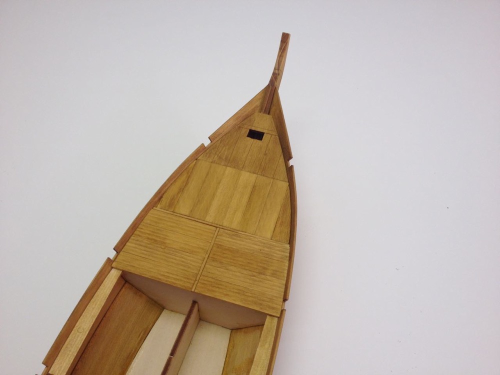
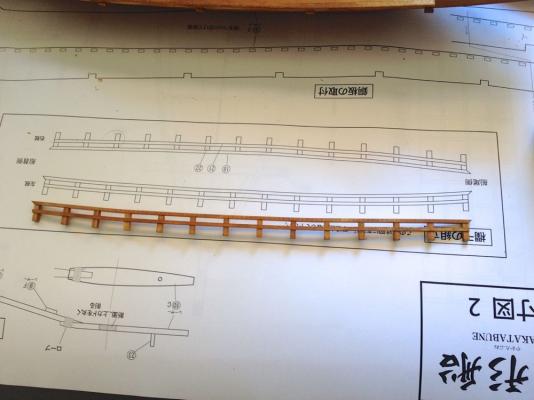
A quick update... It's time to start deck planking. Translated text: Step 7 Installing the Forward Deck - Pt 2 The only full line of text in this section is repeated and simply says: Trim the outside edges to fit against the hull planking. Deck planking on these Japanese boats varies with some planks running fore-and-aft and others running athwartship. Unlike the Hacchoro, thin strips that divide the panels of planks are installed first. Planks are glued together to form panels according to the plans. These are then trimmed so that their edges fit the shape of the hull. Because I shortened that pre-cut deck piece in the last posting, I had to compensate by making the next section of planking just a tad longer. I first glued the dividing strip into place, then marked a piece of planking stock to the proper length. I used that to set up my Chopper III and cut the necessary planks to size. The rear set of planks appear to extend beyond the edge of bulkhead 3. I'm not sure why that is, but I expect I'll find out soon enough. Clare
- 106 replies
-
- 9
-
-
- Japanese boat
- Wasen
- (and 2 more)
-
HMS Alert 1777 by Jaekon Lee - 1/64
catopower replied to Jaekon Lee's topic in - Build logs for subjects built 1751 - 1800
Incredible work Lee! Well, if I can get up enough momentum, I'll have to finish my paper model, so I can take inspiration from your work and get back to wood. And there's a LOT to be inspired by here – Not that I could ever achieve anything close to what you've done! Clare