
Bedford
-
Posts
1,299 -
Joined
-
Last visited
Content Type
Profiles
Forums
Gallery
Events
Everything posted by Bedford
-
 This is a build from which I will suffer some degree of withdrawal, every time I open the site I do so with great anticipation that Valeriy has a new post on this magnificent build.
 -
We tend to be our own worst critics but then we build for our pleasure so must please ourselves. I think it looks pretty damn good.
-
Absolutely stunning Keith, I think I'll be suffering withdrawal symptoms once the pics stop coming
-
Now you've got me worried, band saw, chain saw, circ saw, jig saw, scroll saw, super sharp model making saws and various hand saws and to date, no stitches in 61 years. What's around the corner!!! Mind you I have left a few drops claret in most jobs in one way or another. Glad your injury wasn't too serious though!
- 536 replies
-
- 3
-

-
- Quadrireme
- radio
- (and 1 more)
-
I think that's somewhat a shame, modern bureaucrats killing off old skills. Here in Aus the Sydney Heritage Fleet recently relaunched the steam ship John Oxley after 30 years on the hard. All hull plates have been replaced and RIVETED as per original, they did the same on the James Craig and S.T. Waratah has a riveted hull too. The governing bodies really should recognise and allow historically correct work on these vessels.
-
Keith, I'm biased but I don't reckon you can beat Ena. I've been aboard a few times and the details would really test you. Not to mention she is a museum ship now at the Australian National Maritime Museum.
-
Interestingly, in the book Hand, Reef and Steer by Tom Cunliffe he states that the jackyard topsail should be raised on the port side only. Although it will not be as efficient on the port tack it still works and the reasoning is simple bearing in mind he would be referring to English vessels with a job to do, short voyages and not many hands. The sail has to be raised and lowered on the lee side of the rig for obvious reasons and since doing so is a busy affair you don't want to have to leave it to tack away to avoid another vessel. Having it on the port side means you raise or lower it when on a starboard tack and therefore have right of way over other vessels.
-
I'm nobodys hydrological engineer (don't even think that's the right term) but I'd imagine that the oars sweeping in a fixed test like that will mostly stir the water into eddy currents and not result in much in the way of thrust but when on a floating boat they will work more as they're designed to which involves moving the boat rather than moving much water. I think it may surprise you.
- 536 replies
-
- 2
-
-
- Quadrireme
- radio
- (and 1 more)
-
I admire your determination and commitment to this, for what it's worth I think the 0.4 (last) stroke style is the best
- 536 replies
-
- 2
-
-
- Quadrireme
- radio
- (and 1 more)
-
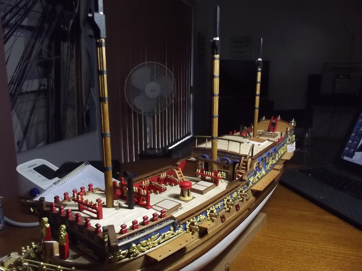
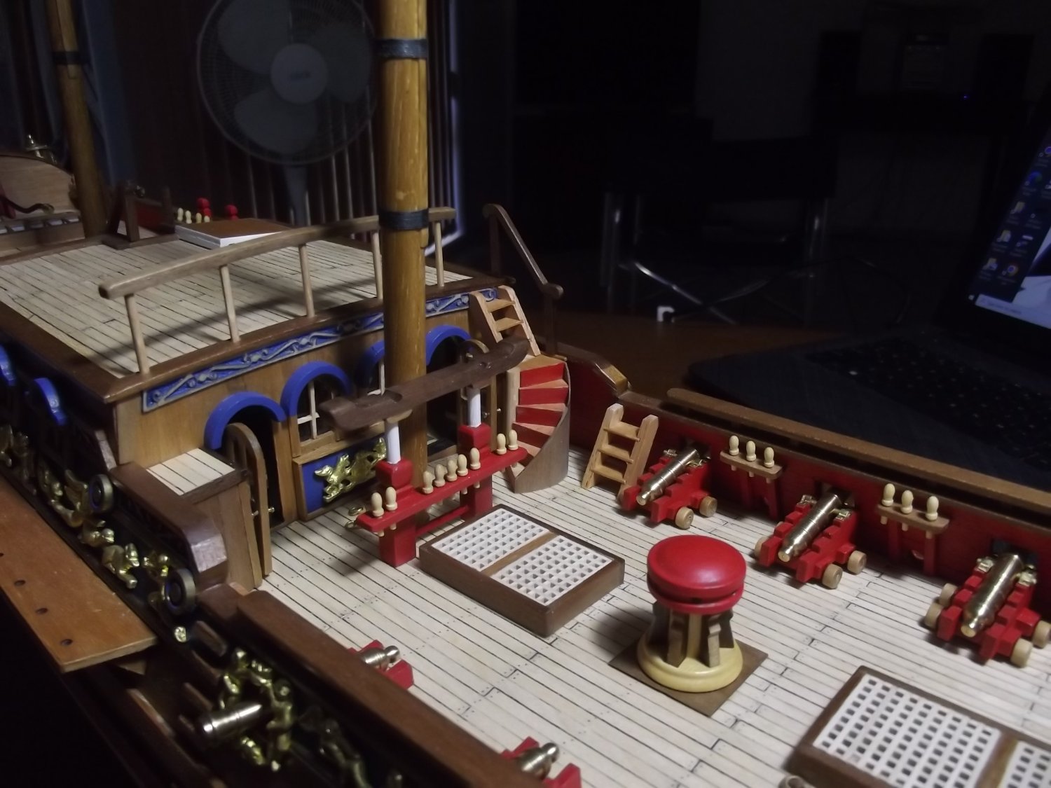
It's been a while between updates but I've fitted the kings cabin doors and made the masts. The wood for the masts was really white so I stained it in Baltic pine and finished them in carnauba furniture wax which looks really nice. All spars will get the same treatment.


-
Mate, this just keeps getting better! That is a huge slab of canvas to haul up from below and you raised it from the correct side too
-
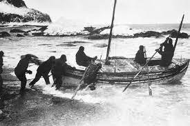
I wouldn't worry about it looking top heavy, it would have been a very heavy boat and may have even had some ballast in the bilge. Shackleton put about 1 ton of rocks into the James Caird in order to sail it from Elephant Island to South Georgia after Endurance was crushed by ice and sank.
-
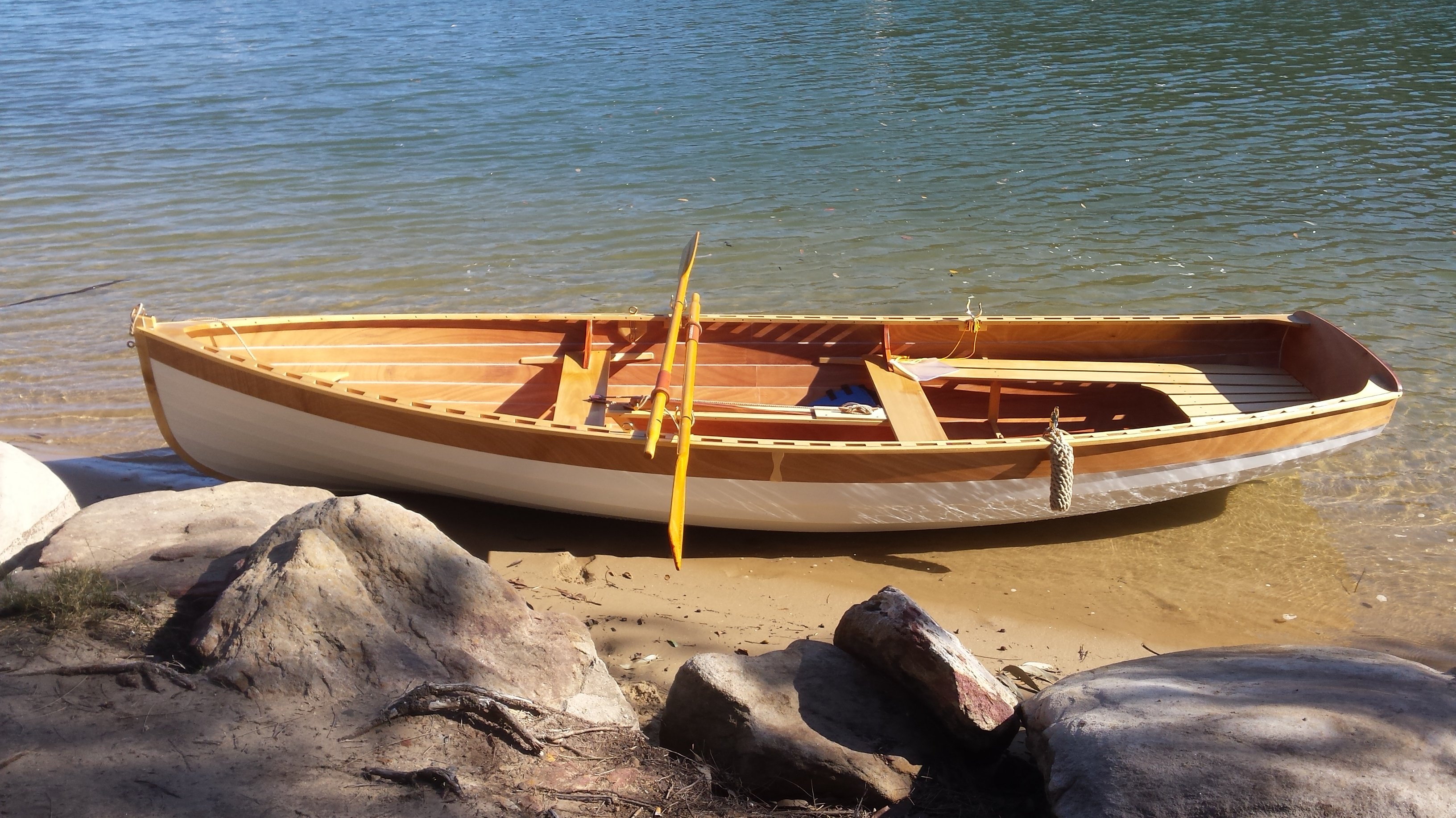
According to Iain Oughtred the rowlock should be 150-180mm above the thwart (6-7") so you can work back from there to set the height of the thwarts. I'm 6'2" and my rowlocks are at 200mm (they were 180 but the oars didn't reliably clear the gunwale so I raised them 20mm) and they are perfect. You should also be able to work backwards from the thwart height to achieve a comfortable floor height. For anyone who isn't familiar with Iain Oughtred, he is one of the premier small boat designers. world famous for his beautiful designs. As for the interior finish, it's not uncommon to paint below the sole and oil above. I agree that the difficulty in sanding to a smooth finish inside due to all the obstructions may have a negative effect if painted.
-
Mate, you don't like making life easy for yourself do you? I'm looking forward to this.
-
Just found this build and I'm interested. If I may throw a curve ball re the walrus (I built a model of it as a kid) roundel. I learned recently that due to an American pilot attacking an Australian aircraft because he saw a solid red circle and assumed it to be Japanese the red inner circle was deleted. I'm not sure when this took place but you might like to look into it. Eventually the red circle was replaced by the now very well known red kangaroo but I've heard from a naval air commander that this happened straight away while others have said the roo wasn't introduced till after the war.
- 88 replies
-
- 4
-
-
- Australia II
- Finished
- (and 2 more)
-
One I taught my son was a 2kg Milo tin (think tin food container) with a press fit tin lid. Make some very small holes in the lid to facilitate air flow. Make a 6mm hole down very low to take a pvc tube of safe length. Take it outside. Place a half cup of flour in said tin with a lit Tee light candle Secure the lid, step back and just a gentle puff through the tube to stir up the flour. watch to see how high the lid goes. Best done when its a bit dark so you can see the flare up. Not that I'm recommending such activities
-
Keith, I had assumed a snug leather covering on the strops and of course that's impossible to recreate at this scale, have you considered just painting them in a suitable colour? A few heavy coats would pass for leather to a blind man on a galloping horse.
-
The fore and aft lines may be foot ropes. How were the wire strops covered to protect the wood work, bit hard to make out from the pics
-
Given the unusual heat you've been experiencing I suppose it's not unexpected for the wood to behave that way. I wonder though what happens when it returns to normal. Will that filler become an issue or will you seal the timber before it has a chance to re-hydrate?