Supplies of the Ship Modeler's Handbook are running out. Get your copy NOW before they are gone! Click on photo to order.
×


robdurant
-
Posts
837 -
Joined
-
Last visited
Content Type
Profiles
Forums
Gallery
Events
Everything posted by robdurant
-
 Hi Vane, Thanks for your encouragement The Anatomy of the Ship on HMS Diana note nine ships as you mentioned. Of these the seventh and eigth (Clyde and Tamar) were built out of fir rather than oak (the latter being in short supply by that point in the Revolutionary Wars. The final, Ethalion, was built out of oak again. You can look up the plans for each of the ships on the Maritime museum's website, and that's where I began my search when I was thinking about building Ethalion instead of Diana. As it turns out, the differences between the sister ships are somewhat lesser than the differences between the kit and the actual frigates. These differences include the width of the stern, and so the layout of the gallery and stern lights, etc..., the layout of the gun ports, and the layout of the channels to name but a few. The more you look, the more you'll see subtle differences. The following is a side-by-side comparison of Ethalion, Artois, and Jason (from the RMG plans) compared to the Anatomy of the Ship plans for Diana to give you an idea of some of the subtle differences. If you look at the mizzen channels for Jason and Artois you'll notice they're split, whereas Ethalion (and Diana from AOTS) are the same. That has a bearing on where the chainplates land around the gunports towards the stern, but the hull shape remains unchanged. One of the more noticable differences as well is the bulkheads on the quarter deck... on Ethalion here. they're open - vertical pillars with a rail on top. On Jason and Diana below, they're enclosed (as the kit Diana depicts)... I've chosen to build them open - a decision I may regret when I get there! but I believe Ethalion's rails were enclosed in a refit. Also Ethalion's rails terminate at the fore end in a vertical... the others are more ornamental. The diagram above is comprised of pictures from the following links from the Royal Museums Greenwich website: http://collections.rmg.co.uk/collections/objects/82225.html (Ethalion) http://collections.rmg.co.uk/collections/objects/82174.html (Artois) http://collections.rmg.co.uk/collections/objects/82195.html (Jason) Also, the profile from diagram A1/1 by David White in Anatomy of The Ship - The Frigate Diana. For comparison purposes only. I trust having cited these there will be no copyright issue, but please advise me if this is incorrect as I will happily remove the image. Having said all this, my primary desire was to build a ship that hadn't been built before. One must be careful when doing this not to accidentally end up using plans of other ships that had the same name (i.e. Ethalion 1802). I found following the historical trail of the ship fascinating, and it really did feel like I was treading on scarce travelled paths in doing so. I was able to go into the National Archives and read the master's and captain's logs which was a true privilege. The Diana kit is a great challenge, and a tremendous kit... it's not only big, but about as beautiful as shipbuilding got. I wish you every success should you follow me and others building these frigates. Do make a build log! It'll show me where I could have done better
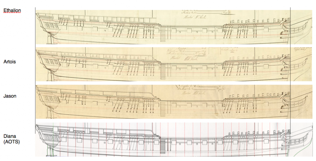
-
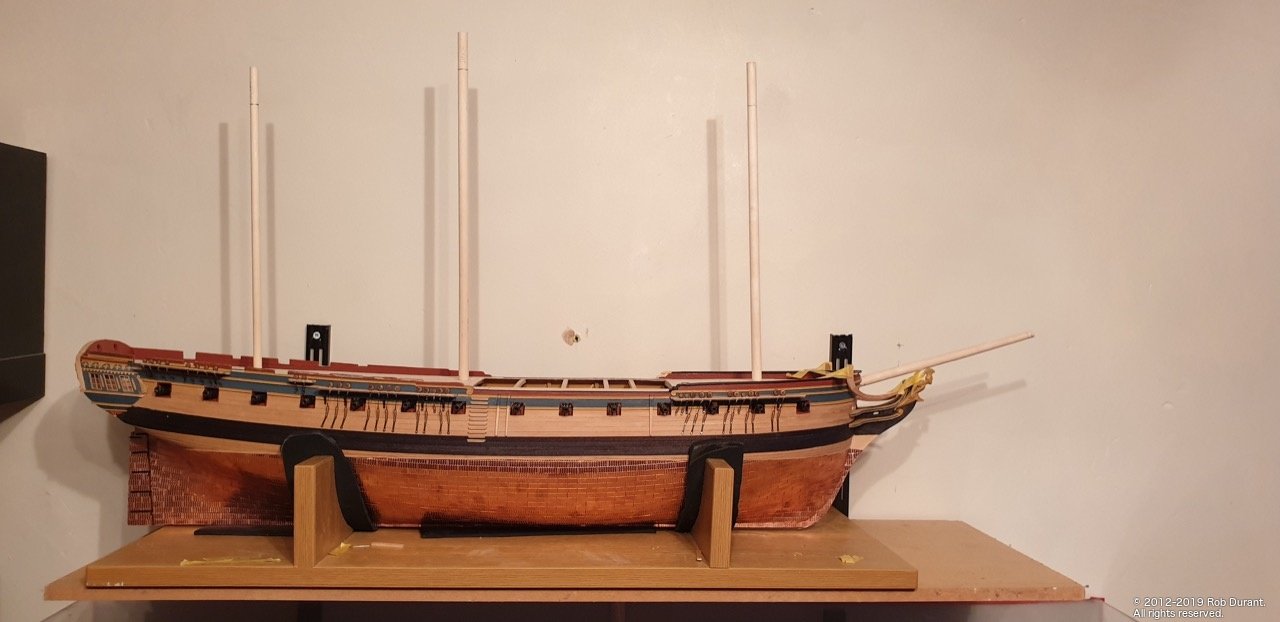
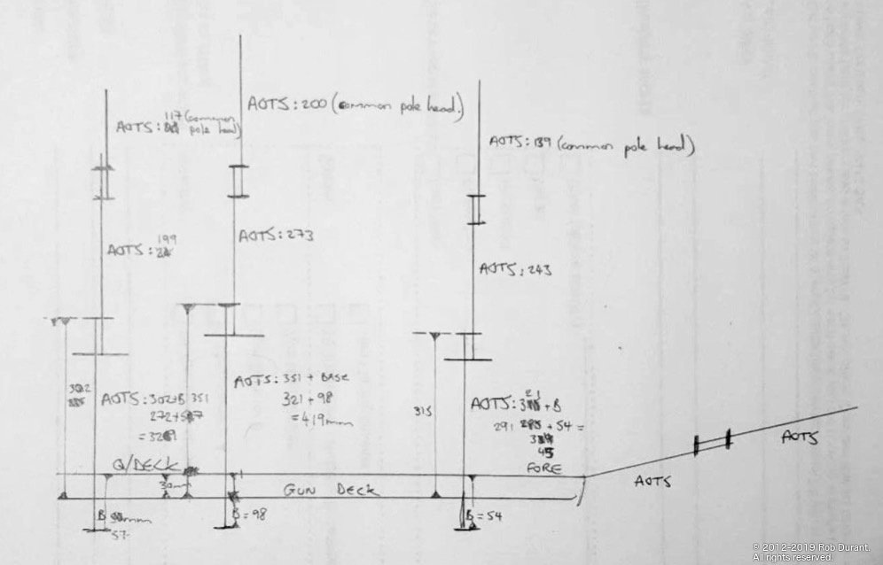
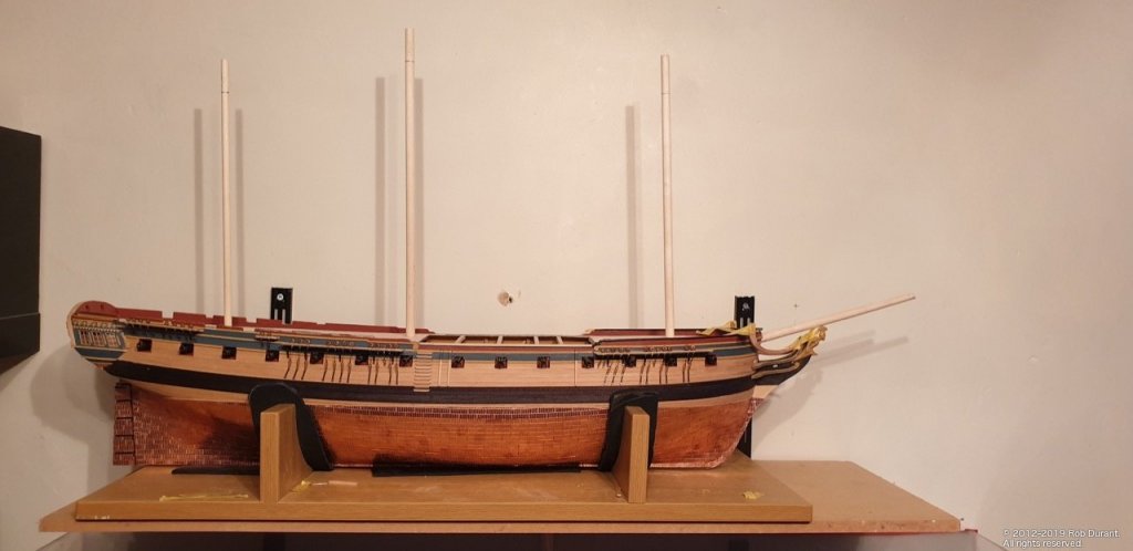
Well, I couldn't resist - The stump masts were looking a little.... stumpy? So I sat down and worked out what lengths I thought the masts ought to be... AOTS has them as being significantly shorter than the Jotika plans - two to three centimetres. This is what I came up with... So the measurements are taken from the bottom of the mast to the upper deck (marked "B") - this was measured from the stump masts, I'd already made. Then the second measurement was taken from AOTS diagram F1/5, F1/6 and F2/1 from the upper deck braces to the top of the mast. By working out the distance between the upper (gun deck) and the fore / quarter deck above it (which turned out to be approx 3cm) I could then work out the entire length of the mast from mast step to top. As I said, this ended up 419mm for the main mast, 345 for the foremast, and 239 for the mizzen. Top and TGt masts were also calculated using the AOTS diagrams F1/3, F1/4, F1/5. And here it is, with some scrap left at the top of each mast for when I put it into the lathe to turn it down... In other news, I also attached the channels on the port side today, and drilled the holes for the chain plates to attach to the hull. As always, thanks so much for the likes, and here's to happy building! Rob
-
She's looking great Peter keep up the good work. I've been surprised how this step up in model complexity means I have to draw on my perseverance more. It's all worth it though.
-
Hi Jason, I worked out the dimensions at 5 cm intervals, and then planed, then sanded some 5mm square strip to those widths (they were only shaped on one side, so completely flat on the other. Those were used as the templates on either side of the strips, which were laid down edge down in between those strips. Once held tightly in place with masking tape, they were sanded down with a sanding strip. It took a while, but once done they were all done in one go. The hardest thing was handling all of the strips and getting them lined up and fixed down in the first place. It was an exercise in patience. I've tried to draw the process below... QuarterdeckPlanks.pdf I've also attached the plan I made of the deck based on measurements from my model... (I wouldn't recommend relying on these measurements for yours too much, as I know I could have done a better job with the fairing of some of the bulkheads, so I have a little bit of a bulge on my model, but it gives an idea.) ethaliondeck.20190222.pdf Yes, this really is one of (if not the) most challenging bits of the model. I haven't worked it out yet either, but I'm relying on lots of card templates, eyeball 1.0, and plugging away bit by bit. I figured if I got the rails in place, I could start thinking about the gratings. Curved gratings? That does sound like a massive challenge. I think I may go for a number of flat sections... perhaps if the turns were gentle enough a curve could be sanded / scraped in (using a template with sandpaper over the top, or a curved scraped used across, rather than fore and aft) rather than building it curved? Just thinking out loud. I may use the kit supplied parts as a starting point and see what they look like. I haven't made the vanity rail yet, so that's the next challenge. Also, I need to work out how to scrape a nice profile on the head rail as it changes width... and thin it down a bit. Anyway - those are my thoughts so far A few deadeyes to secure on the channels first. Starboard finished, but port still to go. Happy building Rob

-
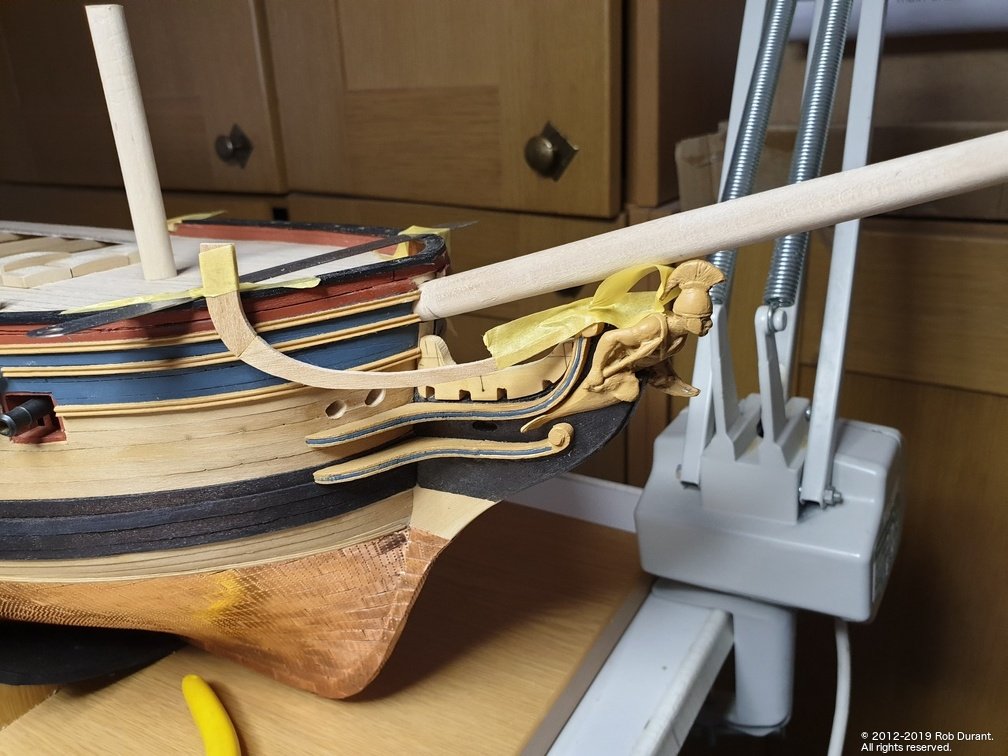
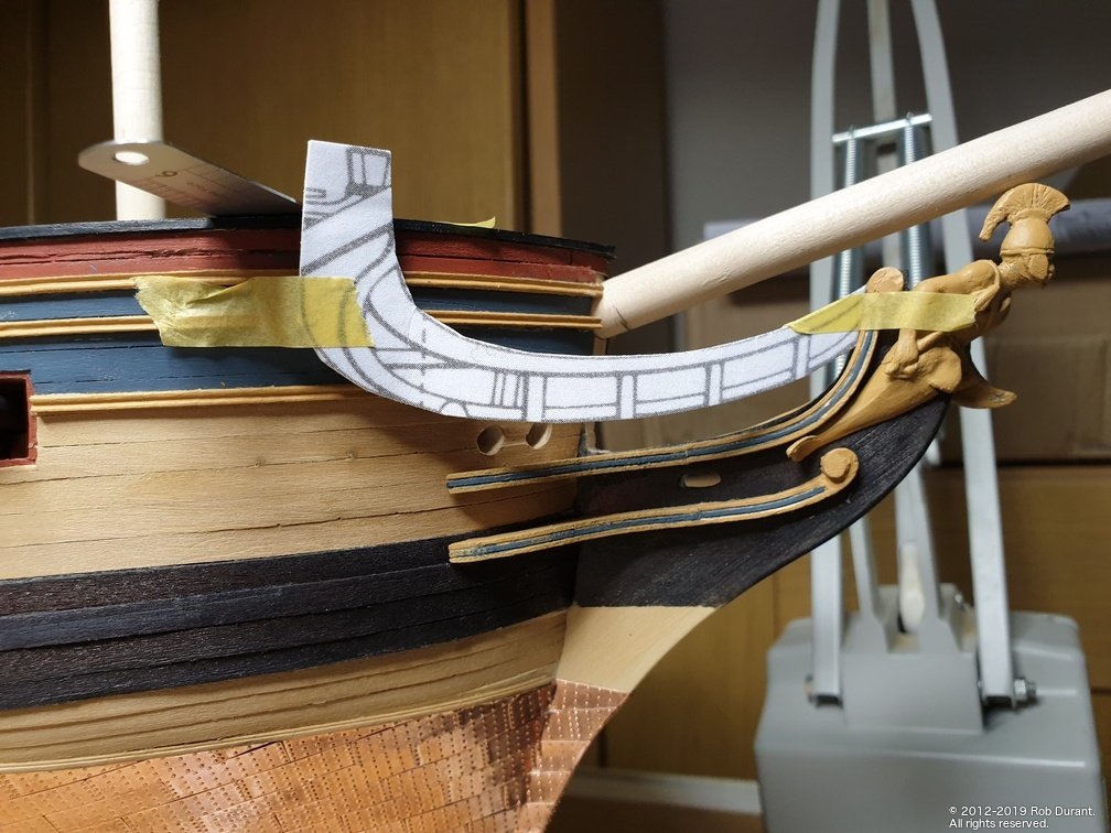
Time for another small update. Small because of late I've found myself sitting staring at the model when I get a little time to work on it, and not achieving much beyond that. Oh well, the ship's patient with me! Anyway... For a break in the channels, I've been looking at the head rails. The top rail needs to be made up before you can see where the other rail, and all of the parts that sit on top of the beakhead go. I wanted to make these parts up so they reflected the AOTS / NMM plans shapes more closely than the kits parts. To that end, I stretched the plans (which started at 1:64) around the bow by 114% on the x-axis, which by my calculations allows for the angle the rails are at on the plans. Then I printed them out, made a card mockup to trial it, and then pritt-sticked them onto some cherry (in two parts so that the grain was running along each part) and cut them out. And here are the results... (roughly taped in position for a trial) The redeeming feature of these headrails is that they're straight when you look at them from the top. It won't be so easy for the middle rail, which seems to bend in every direction possible. This will at least give a good reference point for starting out making that part!
-
Hopefully the soaking will work. I've used the Amati plank nipper which seems to work quite well... The third item down on this link - black plastic: https://www.model-dockyard.com/acatalog/Manual_Plank_Benders.html I know there are differing opinions on these, but I've found them really helpful The other alternative (and perhaps the way that is less damaging to the wood) is heat... You could take a look at Chuck Passaro's planking videos (link below) as they describe this technique. Chuck's results speak for themselves! I haven't tried this with walnut, so I don't know what your mileage might be. Hope that's helpful though. Rob
-
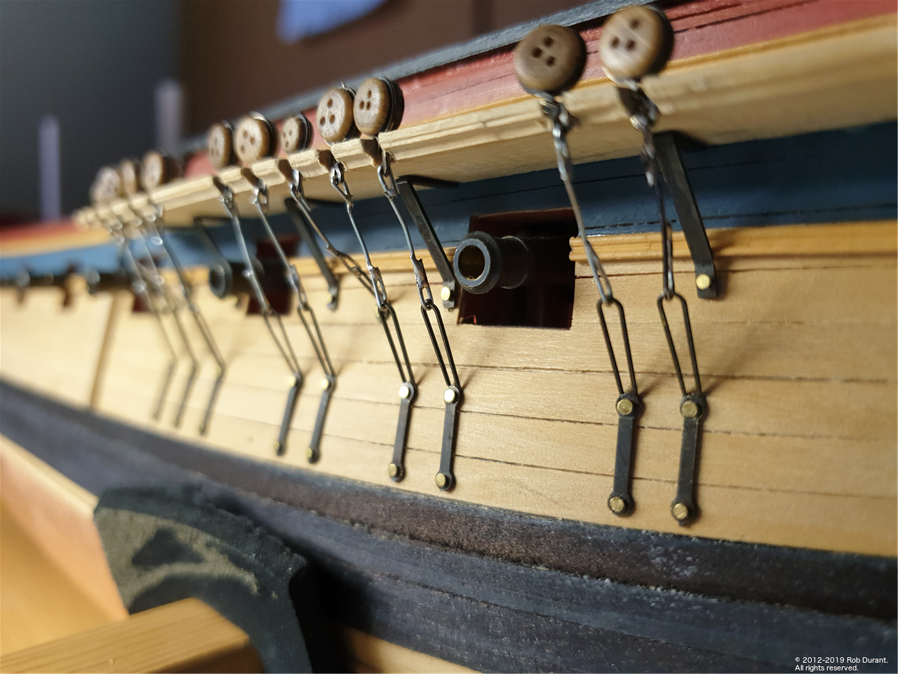
Yep. The photo-etch deadeye strops from caldercraft are perfect. Now the slow and steady task of replacing them begins. I wanted to make the chain between the strop and the hull as strong as possible, so decided to solder the links rather than simply bending them over. That was no problem, but meant the links couldn't be blackened before fitting, which resulted in the chains looking somewhat bling! Fine for a Royal Yacht but not so good for a working Frigate. I tried all sorts of different wires - black enamelled jewellery making wire was much too soft and couldn't be soldered easily. 0.5mm Steel "piano" wire was much too hard to bend - the risk of damaging the ship was too great. Brass wire, as mentioned before, was far too garish, and every slight patch of uncovered wire would stick out like a sore thumb if I tried to blacken them later. In the end some plastic coated gardeners wire came to the rescue. The plastic coating could be stripped off easily revealing what I imagine is some form of mild steel? It bends easily enough (similar to brass), solders really easily, and looks tarnished grey out of the box. With a little extra effort, I'm confident I can dull it down to merge in with the blackened fittings - or at least to the point where it doesn't look too out of place. So. That's the plan. Loop round the strop, and soldier. Place onto channel... Measure and fit other end to fit bracket on hull, and pre-bend... Fit in place, complete bending onto bottom bracket, and solder that end. Time consuming, but I'm moving ahead with confidence that it will be strong enough to resist the pull of the stays, which is the main thing. Once the strops are in place and fully fitted, the gap they sit in is plugged on the outer edge with some scrap box, which is then sanded down to match the edge of the channel. You can see the strops at varying stages of completion on the photo below... Thanks for all the likes. Rob

-
Hi Peter, Sorry - just catching up with modelshipworld, so this information may be too late. I ordered the following: Boxwood Flat Lines Approx. 0.7mm Thick 1 Metre Long 4x option 1: 4.5mm Boxwood Flat Lines x 10 (40 in total) 1x option 1: 3.4mm Boxwood Flat Lines x 10 (10 in total) Black Flat Lines Approx. 0.7mm Thick 1 Metre Long 1x option 1: 4.5mm Black Flat Lines x 10 (10 in total) I also ordered a strip of 6mm square, which has proved helpful for carving small shapes for the rails round the top. In retrospect, I wish I'd ordered slightly more. I used the black flat lines to second plank the wales (in theory to avoid having to paint the wales, although I ended up staining these as well (walnut from the layer beneath was showing through. Anyway - hope that helps. Rob
-
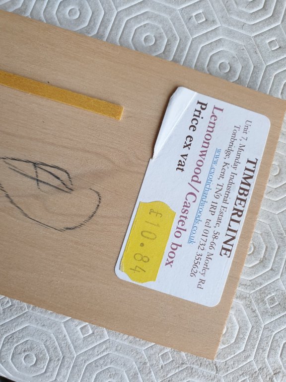
Oh dear. I'm no expert on wood but I ordered some "boxwood" from Euromodels as well... here's a comparison of the colour against the castello and european boxwood I have. I chose notnto use the euromodels wood in the end. It was not only a different colour but very soft compared to the other boxwood I have. It seemed to me much more like the limewood / basswood in hardness. I got my boxwood from: (I have no connection with them) http://www.originalmarquetry.co.uk/category_Lines_and_Stringing_1.htm
-
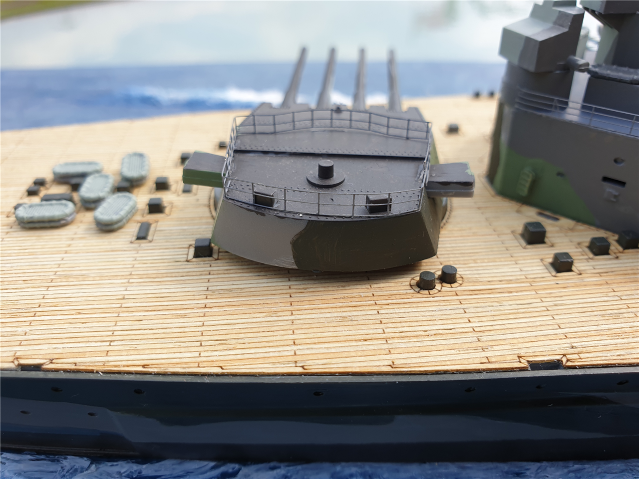
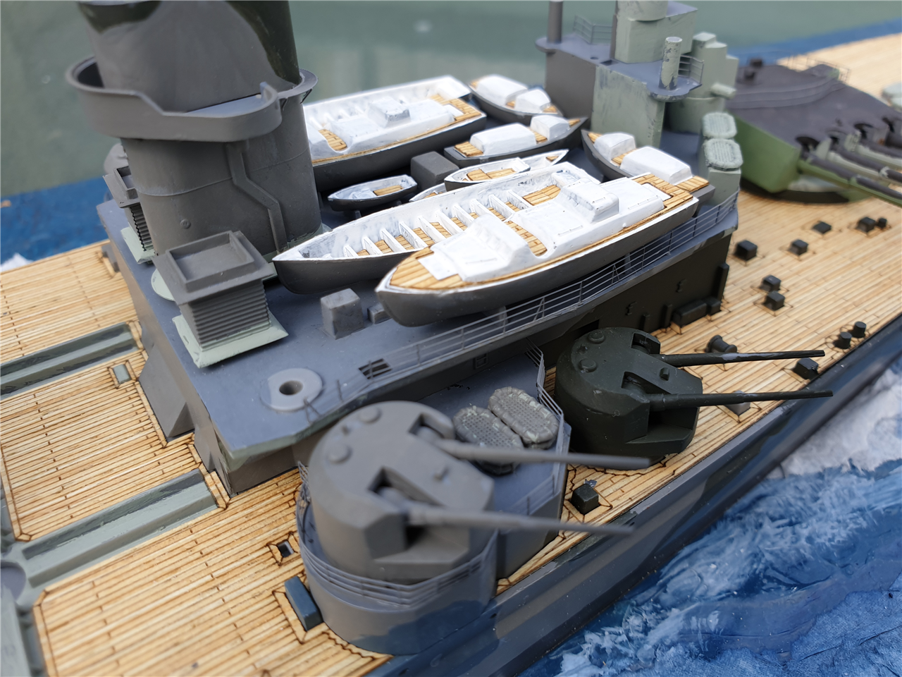
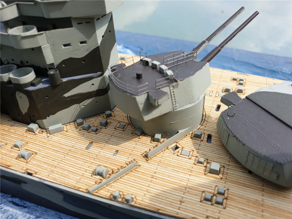
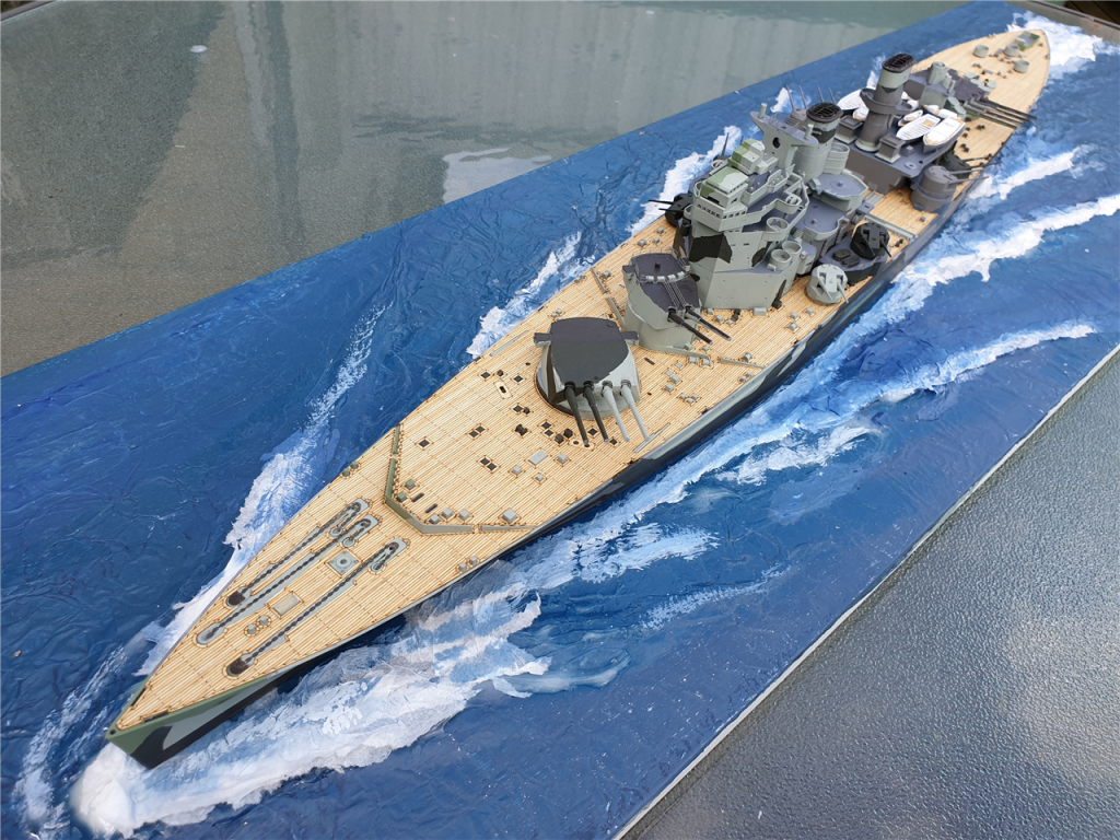
It's been a while since I posted an update.. that's for a few reasons. Firstly, I've been agonising over the deadeye strops. The kit includes some pre-bent wire, which can be soldered shut - the problem being that the joint ends up at the bottom, where the chains connect... It may be my soldering, but I found that the joint was coming loose, and that meant the chain just fell loose. That was irritating at this stage, but I didn't want to start the standing rigging and find deadeyes were coming loose, and I guess they're going to have a fair amount of tension on them by the time they're rigged. So... I scratched my head... and waited while I thought about it. The second reason was that I went away for a few days, and took a model with me, and I still haven't finished it I haven't put a build log on here, becuase it's just for fun and I'm chucking it together. It's a 1/350 Tamiya Prince of Wales with _some_ photo-etch from Eduard on it and a wooden deck. Those of you who know the ship well, or know the photo-etch kit, or know pretty much anything about plastic / photo-etch builds, will see a myriad of problems ... and I don't care it was just for fun! I had a bit of a play making a seascape for it, to make it a waterline model... and here's the current state of it. I'm going to finish it off so I have my boat building desk back to get on with Ethalion. It should be done in the next week or so. Back to the deadeye strops, and I've found a solution. Caldercraft sell them as photo-etch sets separately, so I've ordered a bunch, and that should take the cork out of the creative bottle as they say! I'll let you know how I get on. Rob


-
Kind words Peter. Thank you. If you want to see someone doing a really beautiful job with boxwood you could check out Beef Wellington's HMS Jason... it's also based on the Diana kit but his skills surpass any I have by many degrees. Along with Ray's excellent build, that's where I've been going for inspiration The wales look good from here. I know that the bottom of the wale ended up almost touching the waterline so this may be a good moment to roughly check the waterline towards the centre and make sure the wale won't clash with it when the time comes. Rob
-
Hi Peter Lovely to see another Diana on the way. Looks like you've made a great start! Rob
-
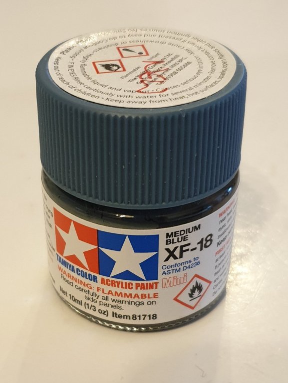
Hi. Thanks very much. I borrowed the idea for the blue from Jason (Beef Wellington). It's Tamiya XF-18 acrylic - "Medium Blue".
-
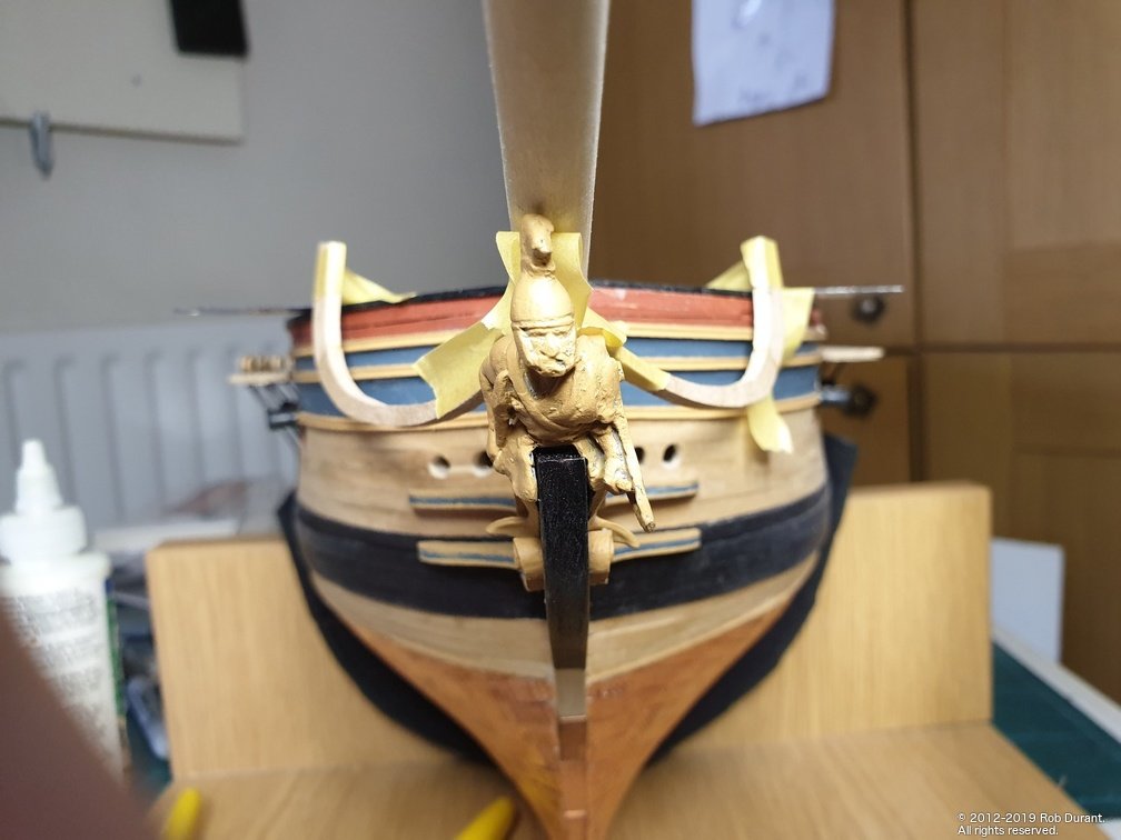
Today I managed to add the decoration onto the port gallery so that it matched the starboard. I've also added the capping rails onto the forecastle. I added walnut strip to the edge of the capping strip to widen it before pre-painting it and then fixing it onto the hull.
- 275 replies
-
- 11
-

-
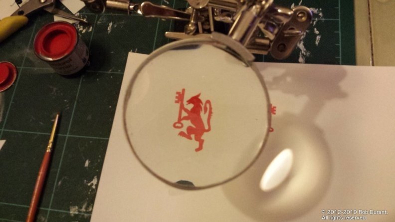
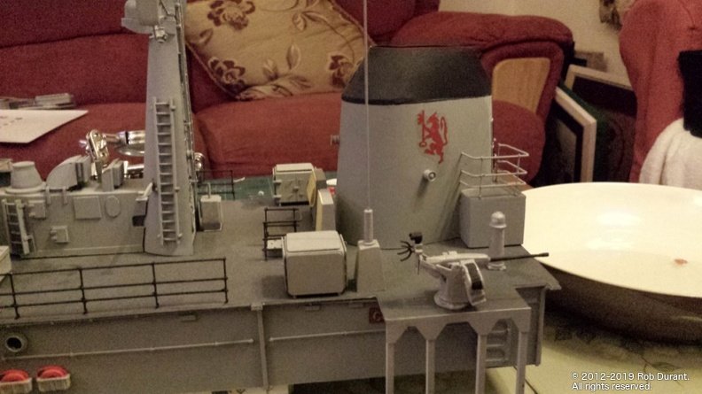
When I had to put a badge on the funnel of my HMS Cottesmore, I tried using printed transparent decal paper but it was too see through where it was printed. So I printed it out then carefully painted in the colour and used that as the decal. This allowed me to get the fine detail but also the painted look I was going for. The whole was then sealed with varnish (and because of the paint didn't run. Perhaps a light grey printed decal gone over with white paint? This was at 1:48 though so you.may find 1:96 lettering too fine for this approach.
- 446 replies
-
- 6
-
-
- zebulon b vance
- deans marine
- (and 3 more)
-
Don't know whether these guys have already been suggested... http://www.becc.co.uk
- 446 replies
-
- 2
-
-
- zebulon b vance
- deans marine
- (and 3 more)
-
Exciting stuff! Pulling up a chair. Rob
-
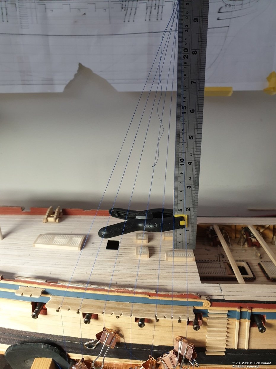
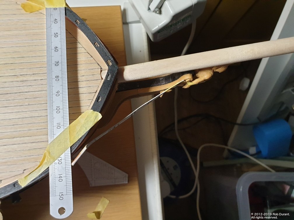
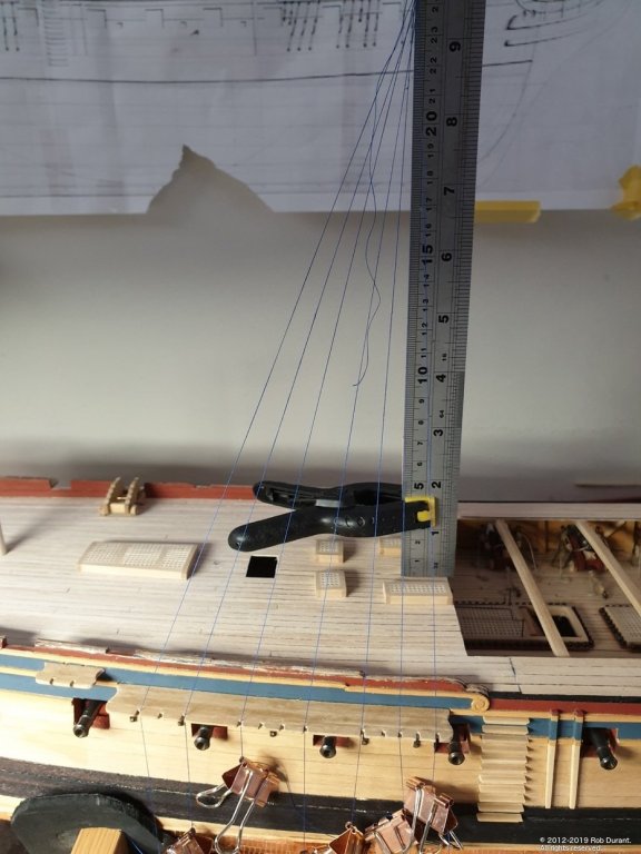
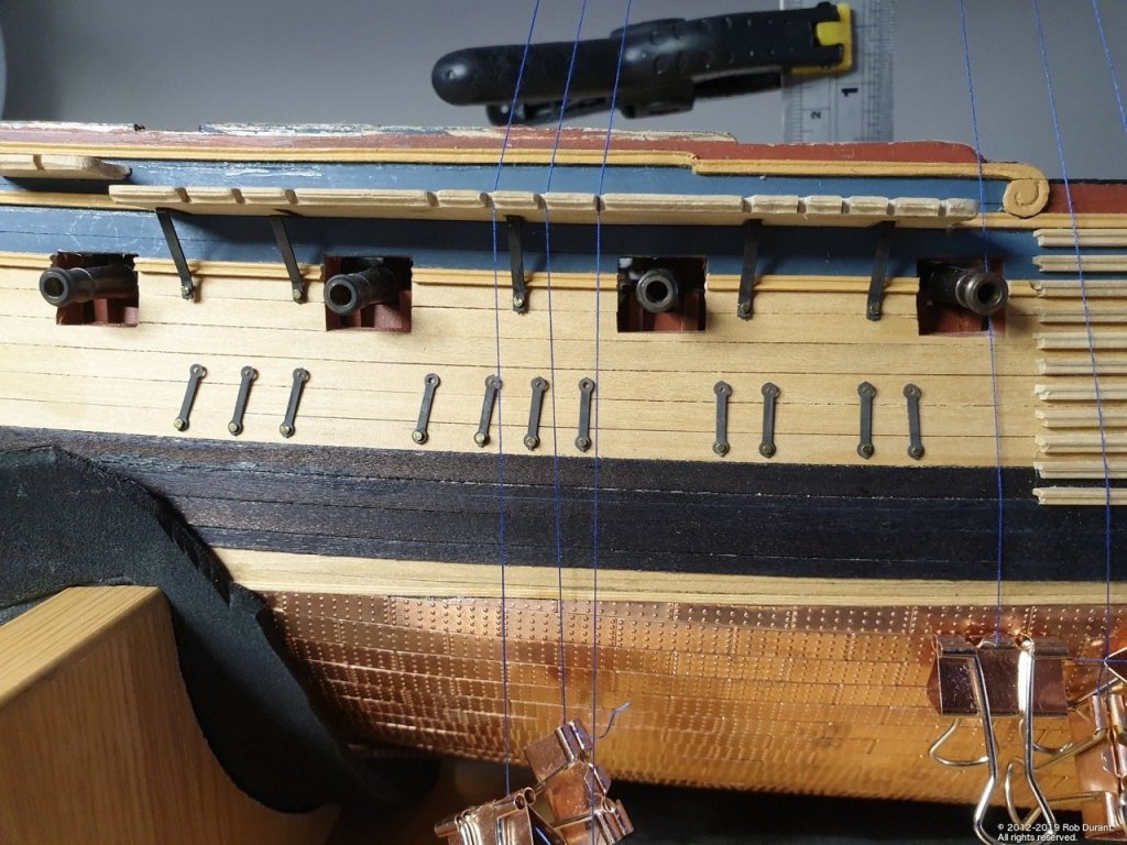
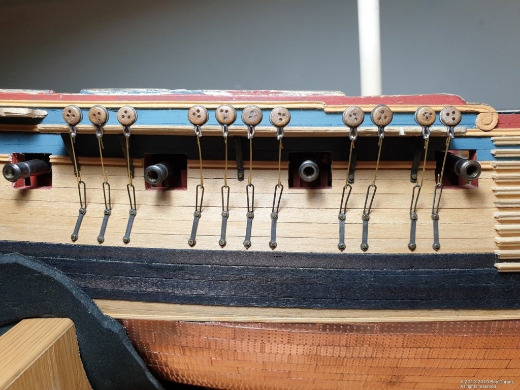
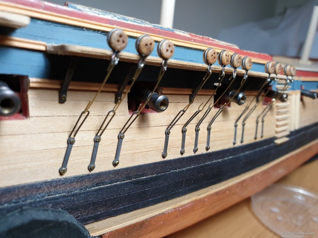
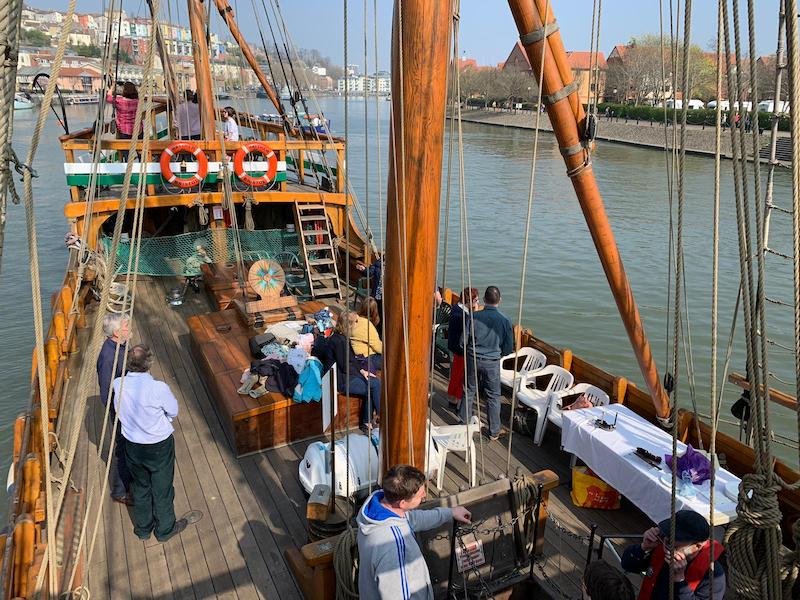
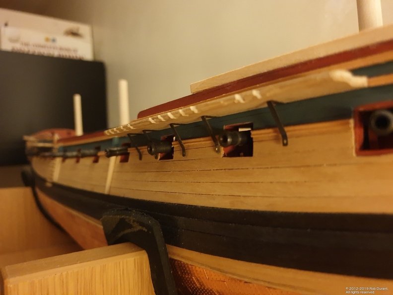
Hi all, First of all, thanks very much for the likes Just a little update. I've been working on the channels and chain links that pass the pull from the stays and deadeyes down to the hull sides. The first job was to get the plates at the base of these links in place. So I put the stub masts in, clamped a 30cm ruler to it them and used cotton thread to show the line the stays would follow. The thread was weighted down with small bulldog clips and passed through the notches in the channels. Masking tape on the hull side allowed me to mark the locations of the pins, and then drill them without marking the hull sides. These are fiddly blighters. I blackened all the photo-etch parts, and now I've made up the brass wire links that complete the links I'm ready to blacken those. Just the 5mm deadeyes on the fore and main channels done so far and dry fitted. To strengthen the parts, I soldered the parts surrounding the dead eyes to make them a closed loop. So far, so good... none of the chains, lined up to follow the lines of the stays, obstruct the gun ports! 😅 And in other news, I had a surprise on Saturday. I turned 40 a few days ago, and my wife had organised a surprise party... in Bristol... a harbour trip on the Matthew (the replica of John Cabot's caravel from 1497)... they even let me steer! (brave of them!) Not something I ever thought I'd do, but a nice way to start a new decade! Rob
-
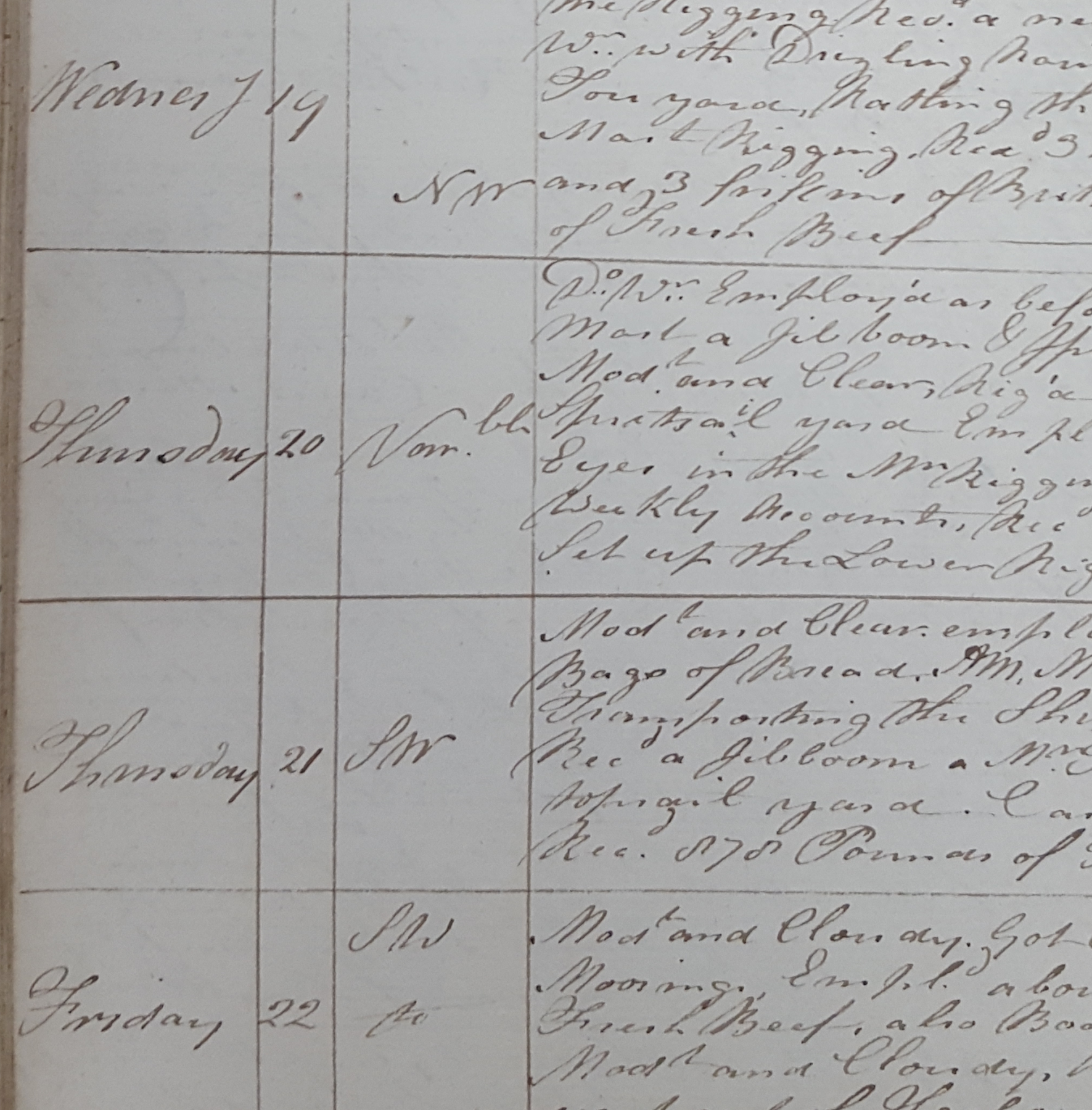
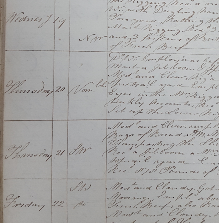
Hi all, I've been spending a little more time transcribing the master's logs for Ethalion. It's a fascinating process... Lots of it is repetitive but then you find passages where the entire rig of the ship is taken down and set up again... As others have speculated in the past, it is clear that lots of knowledge was simply assumed - the passage below logged when Ethalion was moored in Hamoaze demonstrating that nicely... Tuesday 18th December 1798 Varble NNW Light Winds & Cloudy, fitted the Bobstays and set them up. Riggd the foretopmast and Mizen Mast, Sway’d up the fore & main top Masts and set up the fore and Main stays &c. &c. AM Modt and Cloudy, Got the top sail Yards across & Rattled Down the Fore & Main Rigging, Recd 354 Pounds of Fresh Beef Recd also Boatswains stores. It's nice to see the humanity of the Master (James Duckworth) creeping in too... (Not quite a month of Sundays, but seemingly a week with two Thursdays!) . The error continues to the end of the page (with Saturday rather than Sunday) and then suddenly skips back to the correct day... but perhaps the error was never spotted? There have been a few places where that happened. A sign of the similarity of days aboard a ship of war? I found myself writing about putting on the dead eyes on the same day I've been starting to set these up on my build. A pleasing coincidence! For those who would like to read more about the order in which the ship was re-rigged (having had considerable amounts of the rigging condemned), you can find it in the December 1798 entries in the following PDF (a work in progress). LogTranscription.James_Ducker_Masters_ Log17980701-17990630.ADM-52-2983.20190325.pdf More on the build soon. Rob
-
Almost the same in English... https://www.dictionary.com/browse/lath Love these lesser used words... they make our languages rich and interesting. Back to the ship and she's looking terrific. I built a deans kit 20-something years ago and struggled with the printed styrene... the printing didn't seem to be quite accurate (or it may just have been lack of skill on my part)... You're doing an amazing job though. The view along the superstructure is amazing and looks absolutely true... impressive for a structure that long and thin. Keep up the good work! Rob
- 446 replies
-
- 4
-
-
- zebulon b vance
- deans marine
- (and 3 more)
-
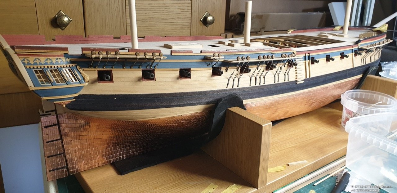
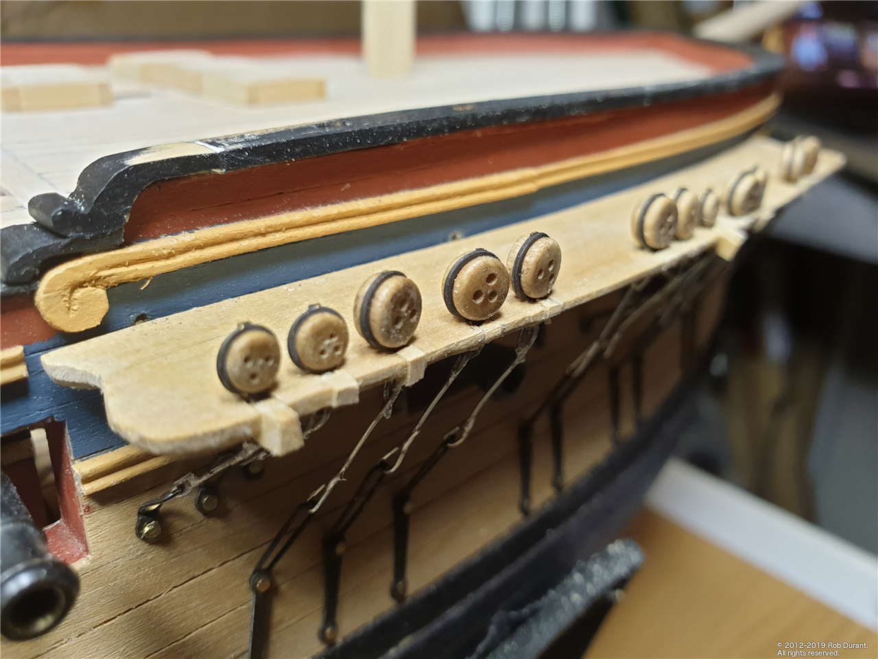
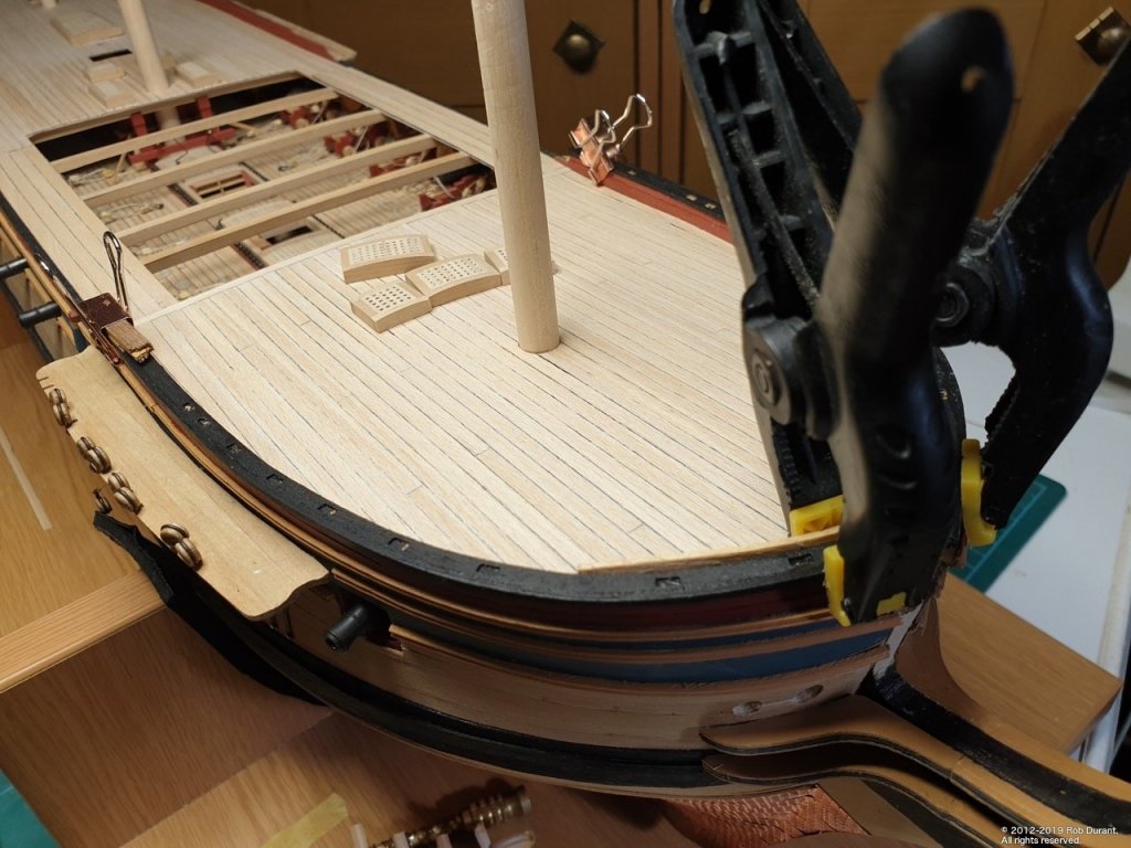
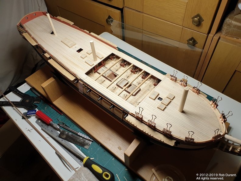
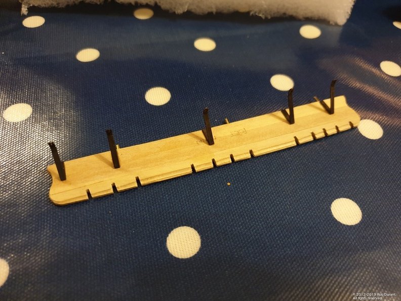
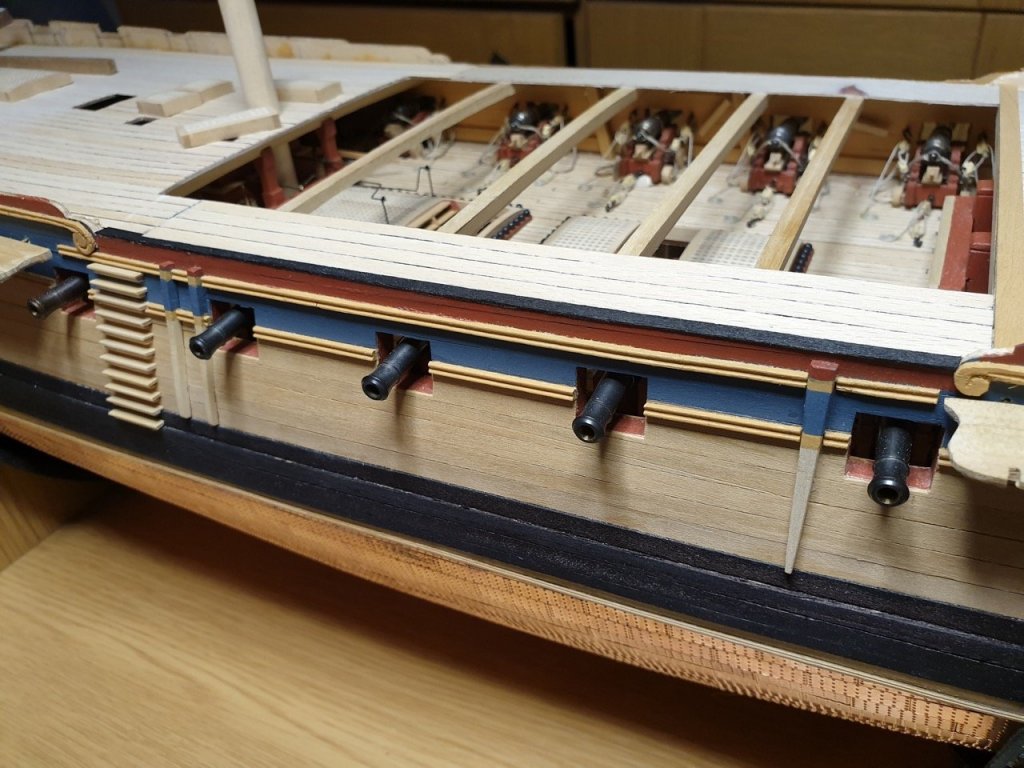
Hi all, A short update. I've completed planking the forecastle, gangways and quarterdeck. The next task was to plank the bulkheads, which were pre-painted red ochre. These could have been yellow ochre, but I figure light levels aren't an issue on an open deck, and I like the contrast. I planked the bulwarks on the quarterdeck, which was simple enough, but when I reached the foc'sle I realised that I'd cut down the hull too far. A good while has been spent building this up again so that the sheer rails look right next to the rail at the top. I think I'm nearly there, but it's tedious, fiddly and time-consuming... I'd work harder to avoid this in the future. Thankfully it's on an area of the hull that's painted. To break the tedium I decided to add the channel supports. As others have noted, there are 22 supplied, and _at least_ 26 are required according to the Caldercraft planks. I reused some of the rudder hinges (which I'd replaced with black card because they seemed too bulky for that) for this purpose. Even then, I reduced the six supports on the main channel to five so there were enough to go round. (One could buy another set of the Diana photo-etch, but at £95 it's a bit steep for 6 channel support brackets! The brackets were blackened first. The channels themselves aren't glued onto the hull yet, so they were removed and the brackets stuck to the bottoms, then the channels temporarily reinstalled. These will need gluing on soon, and once glued on, then I'll drill the holes to pin the brackets to the hull sides. (After a good sleep, and when I'm feeling confident I won't leave the hull looking like a swiss cheese!) I'm very pleased with the results so far. All comments welcome, and all likes appreciated. Rob
- 275 replies
-
- 17
-
-
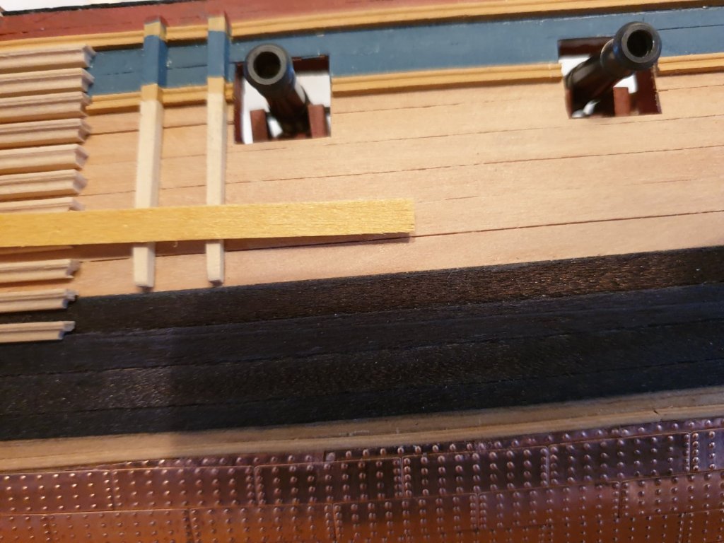
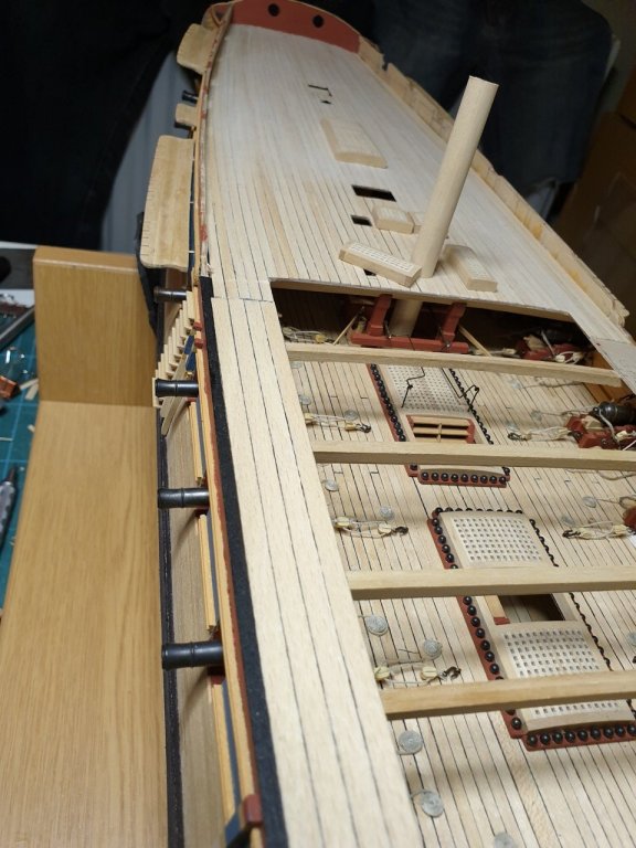
Well, the quarterdeck is planked and the starboard gangway. I've also managed to tidy up the edge of the deck where it meets the hull side at the waist. Really pleased with how that worked out. Not sure whether it needs a yellow ochre trim... I can add that later if I want to. The gangway planking is wider than the quarter deck planking, as per AOTS. On the bottom photo you can see a box strip laid tranversely in front of the gangway planking - I'm still not sure whether I like this effect. I may revert to a narrower maple strip to match the rest of the planking as the contrast is too great. Something needs to go across the deck there, though. Happy building Rob
- 275 replies
-
- 13
-
-
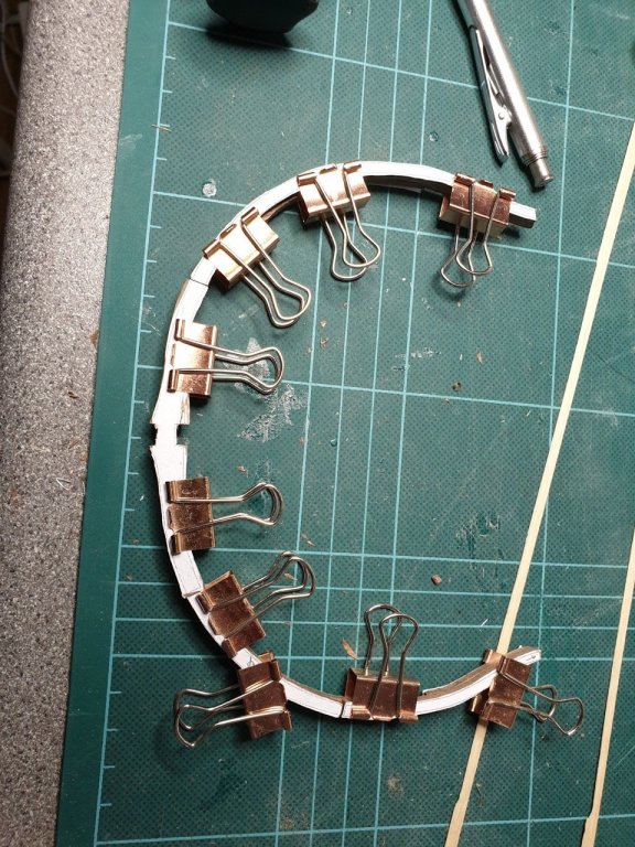
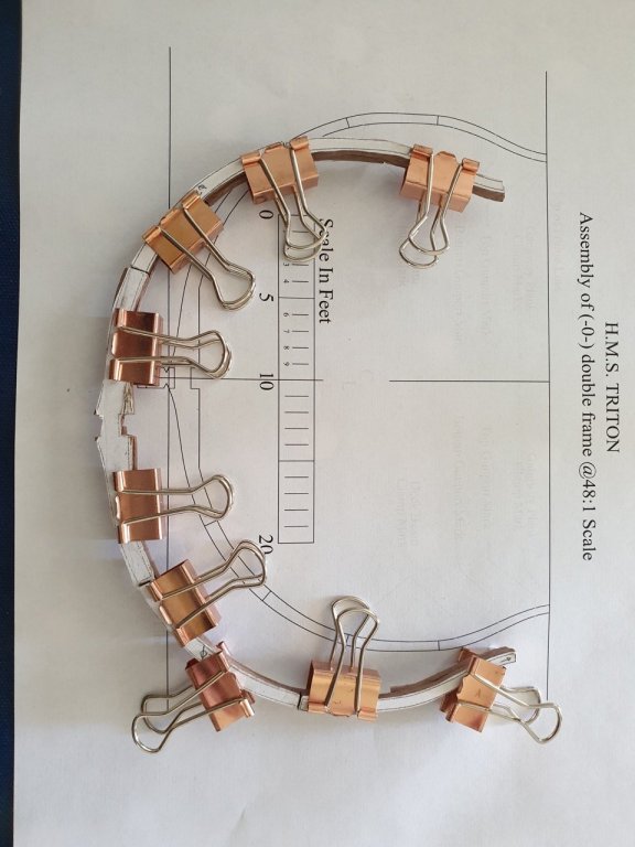
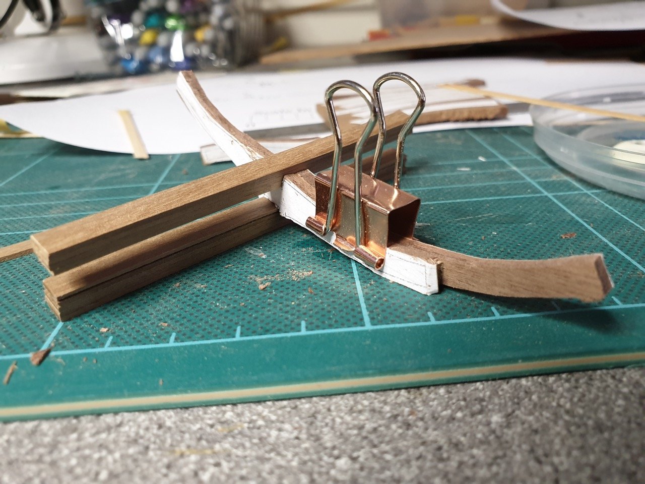
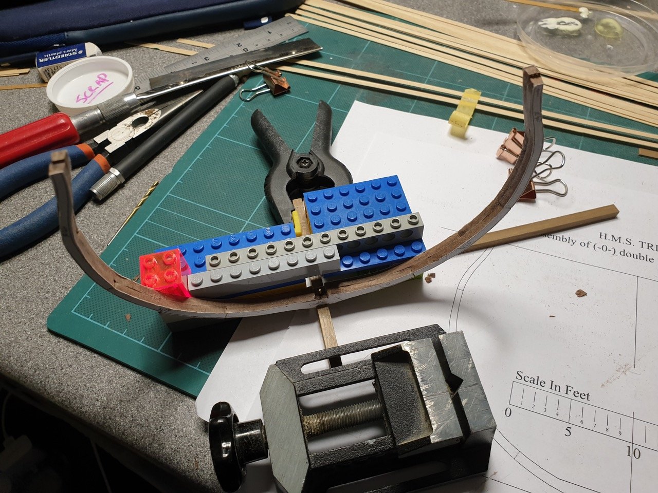
Well, somehow 2 1/2 years have flown by since I last did any work on this... so long in fact that when I came back to have another crack at it, I realised to my horror I'd thrown out the original parts! That said, the process of remaking them today has been educational and I've made some real headway. I realised that I'd been approaching the build by trying to crack a nut with a sledge hammer... This time, rather than trying to sand down the frame parts, I gently carved away the excess with a nice sharp xacto blade.. The walnut was lovely and soft and as long as I approached inside curves from both directions and took it steady, it was surprisingly quick to get a whole frame made. It's by no means perfect, and I'm expecting to remake this frame when I've made some more... but it's certainly teaching me lots. So... here are the pictures of my first full doubled up frame. It's the dead centre frame. I tacked it to the keel with a little carpenters glue to see how it looked and even the process of doing that made me realise quite how fragile this is going to be when i assemble it until I get the horizontals in.