

Kevin
-
Posts
7,036 -
Joined
-
Last visited
Content Type
Profiles
Forums
Gallery
Events
Posts posted by Kevin
-
-
-
8 minutes ago, Landlubber Mike said:
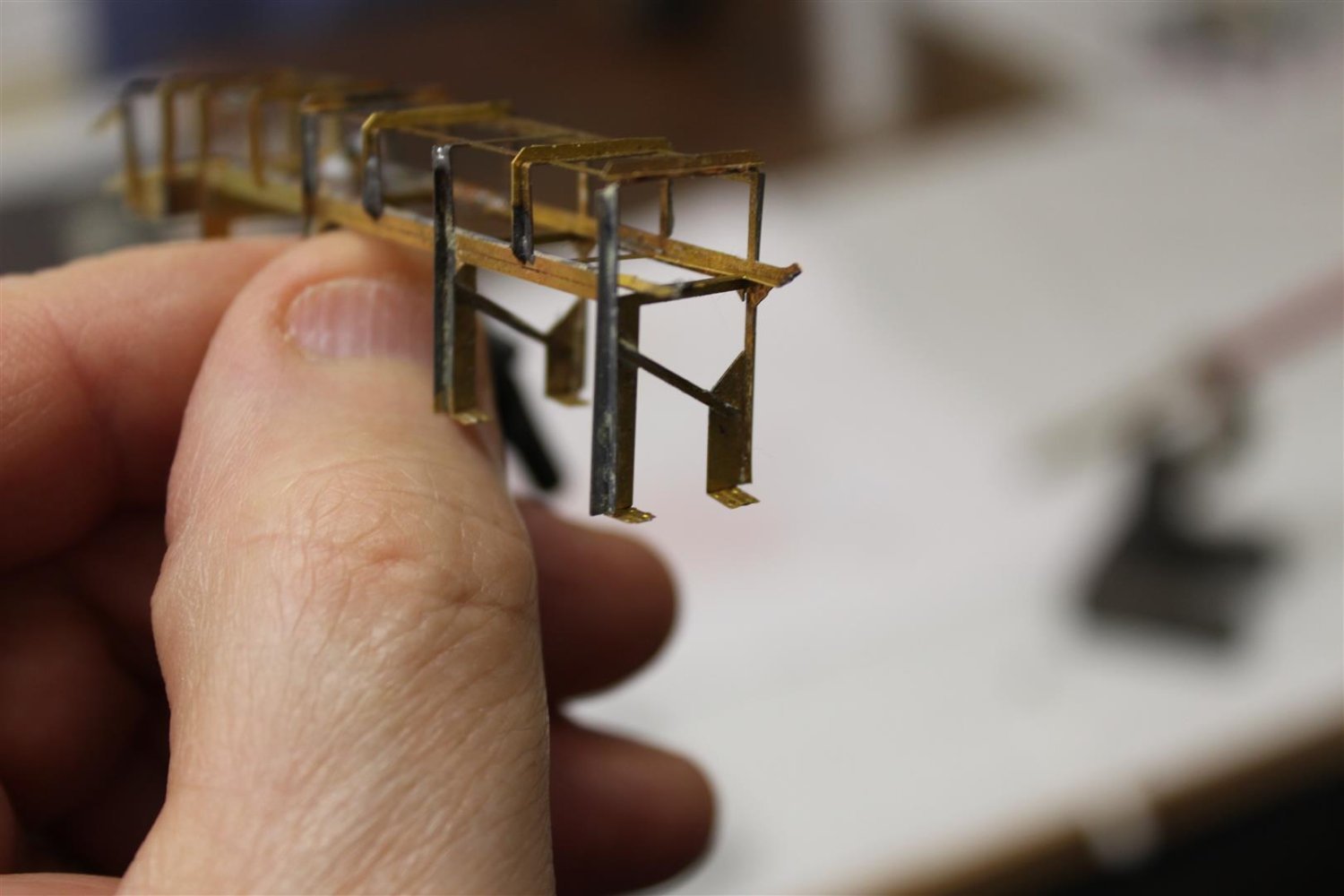
Looks great Kevin. Are you soldering the PE together? If so, you’ve really gotten the hang of it!
yes i am, its a bit messy still in places, but i am now even managing to clean previous bits up
-
good evening everyone
Thank you for comments and likes
apologies for being grumpy for the last few weeks
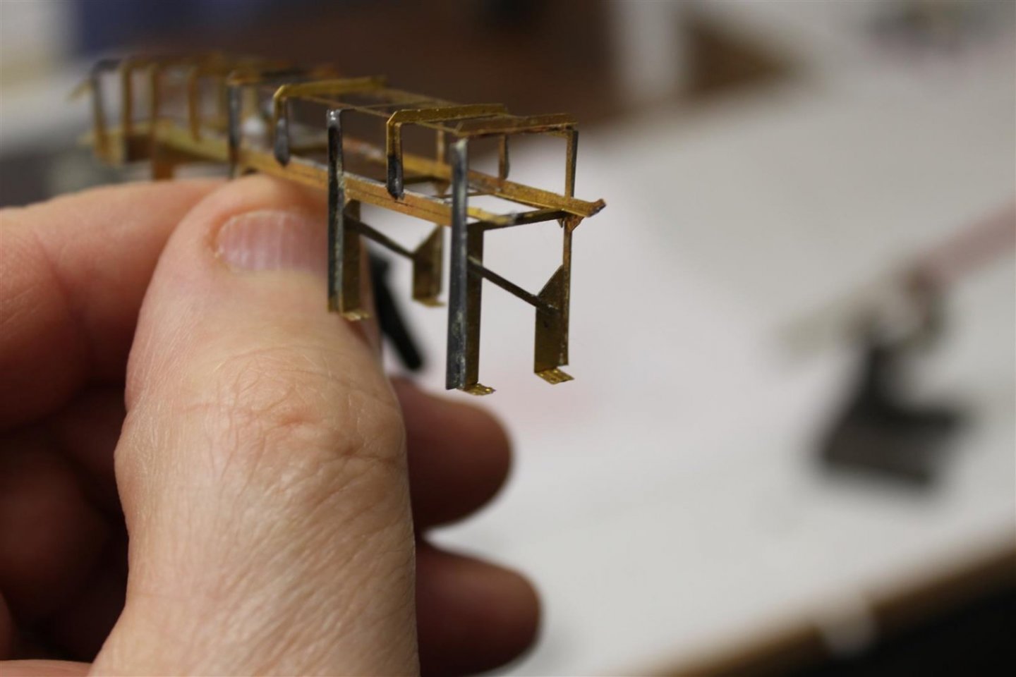
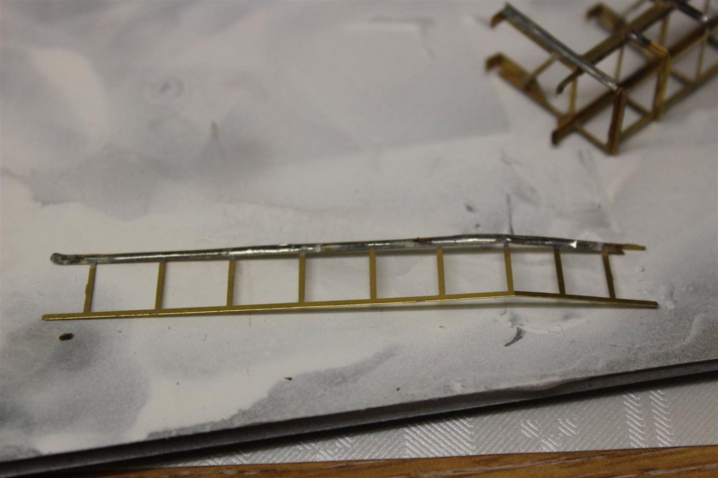
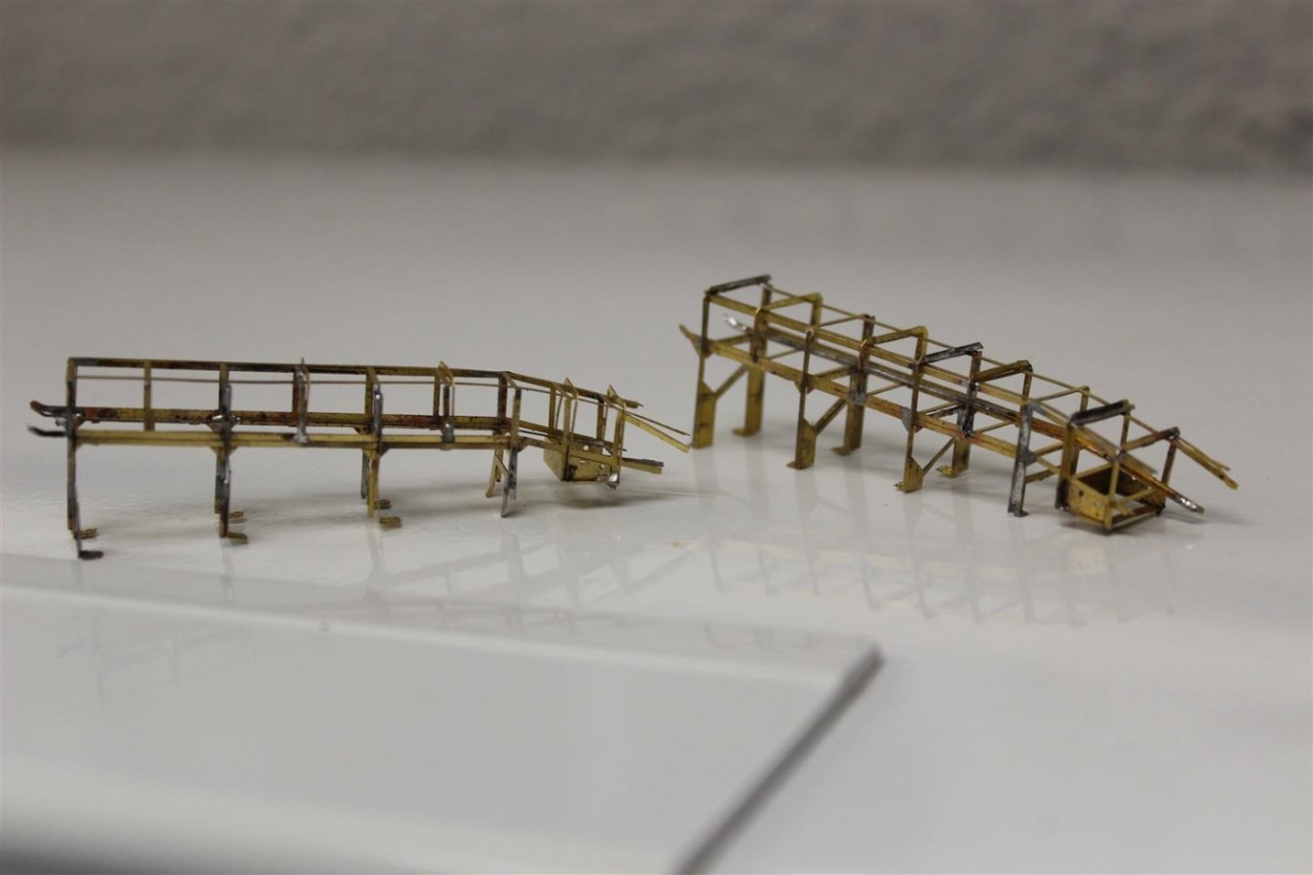
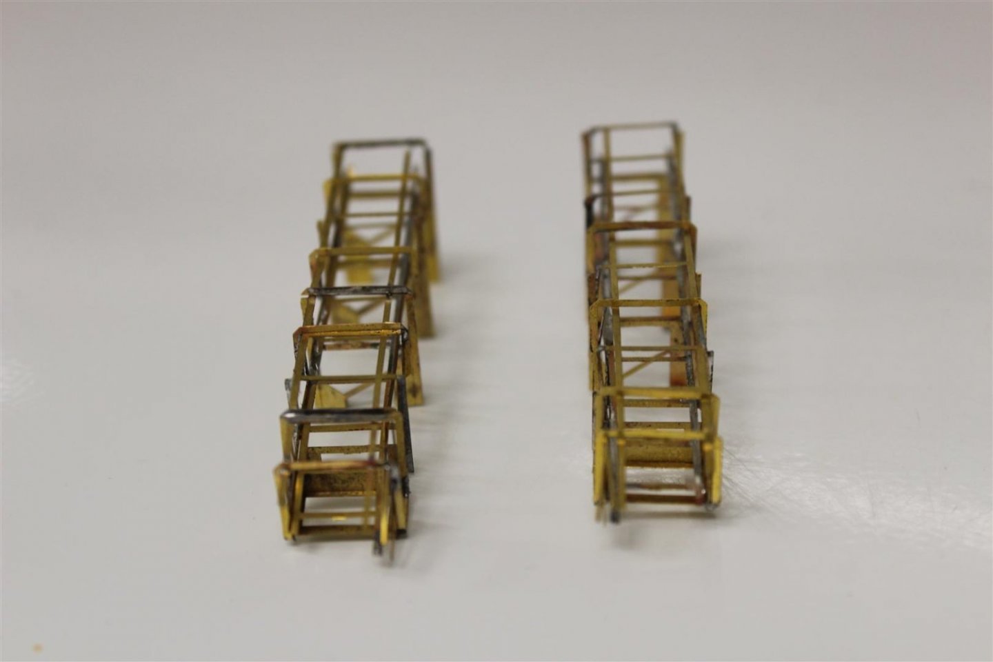
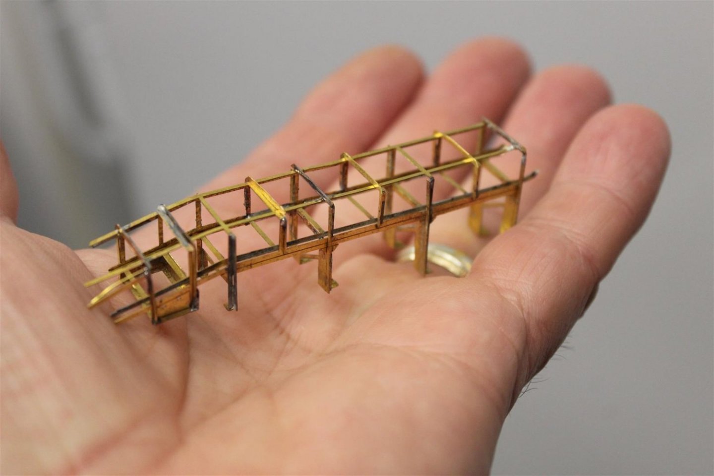
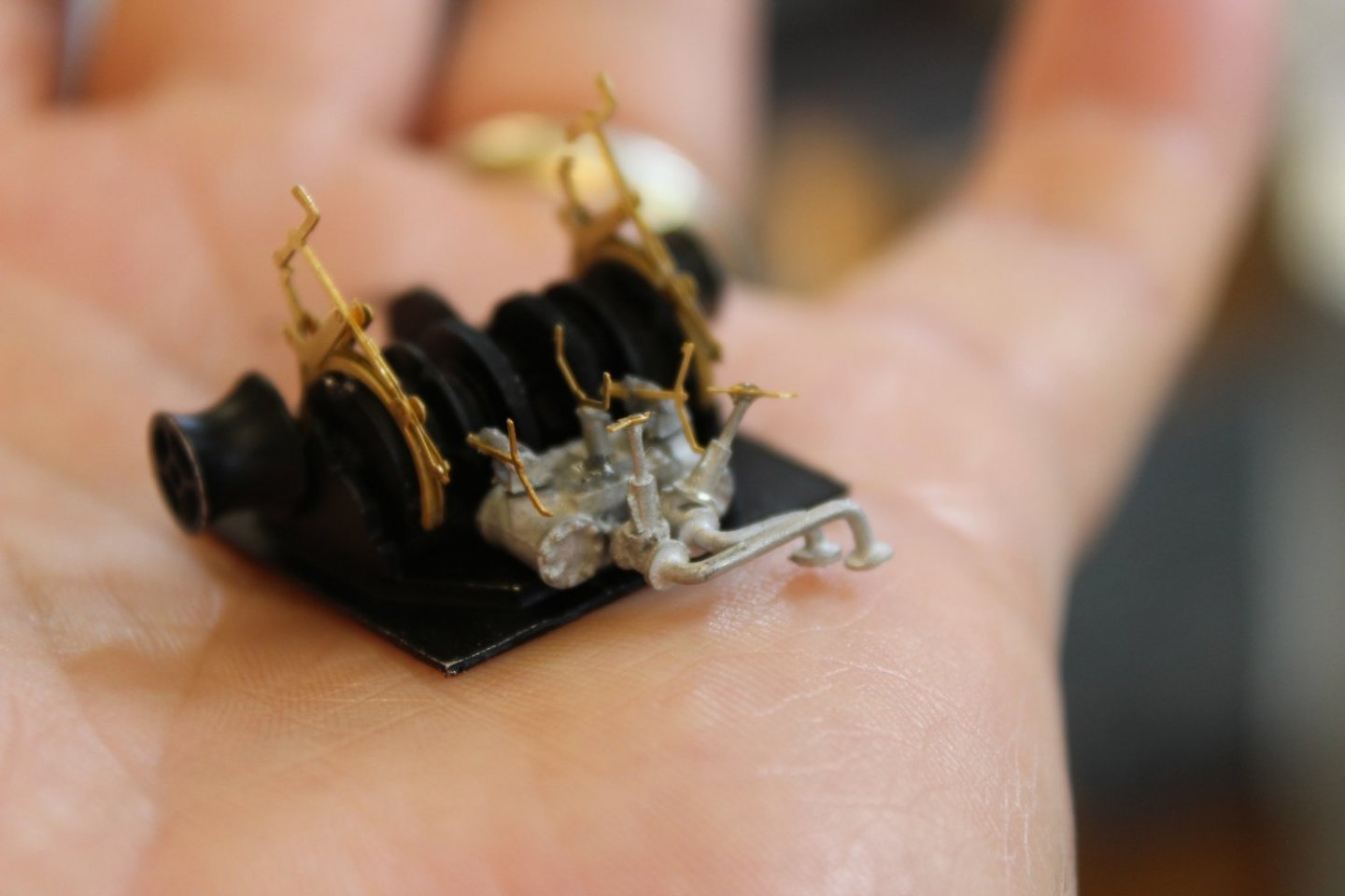
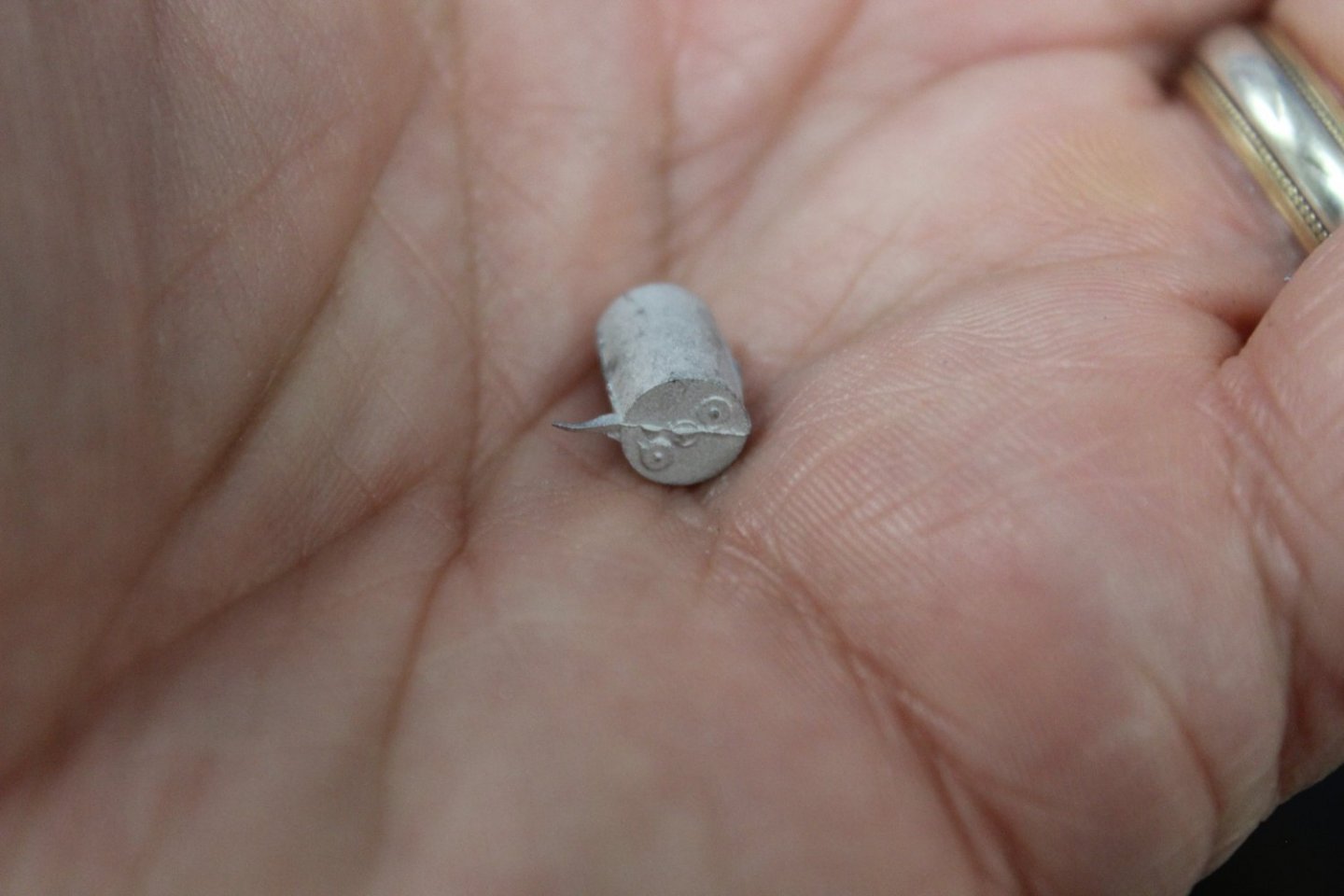
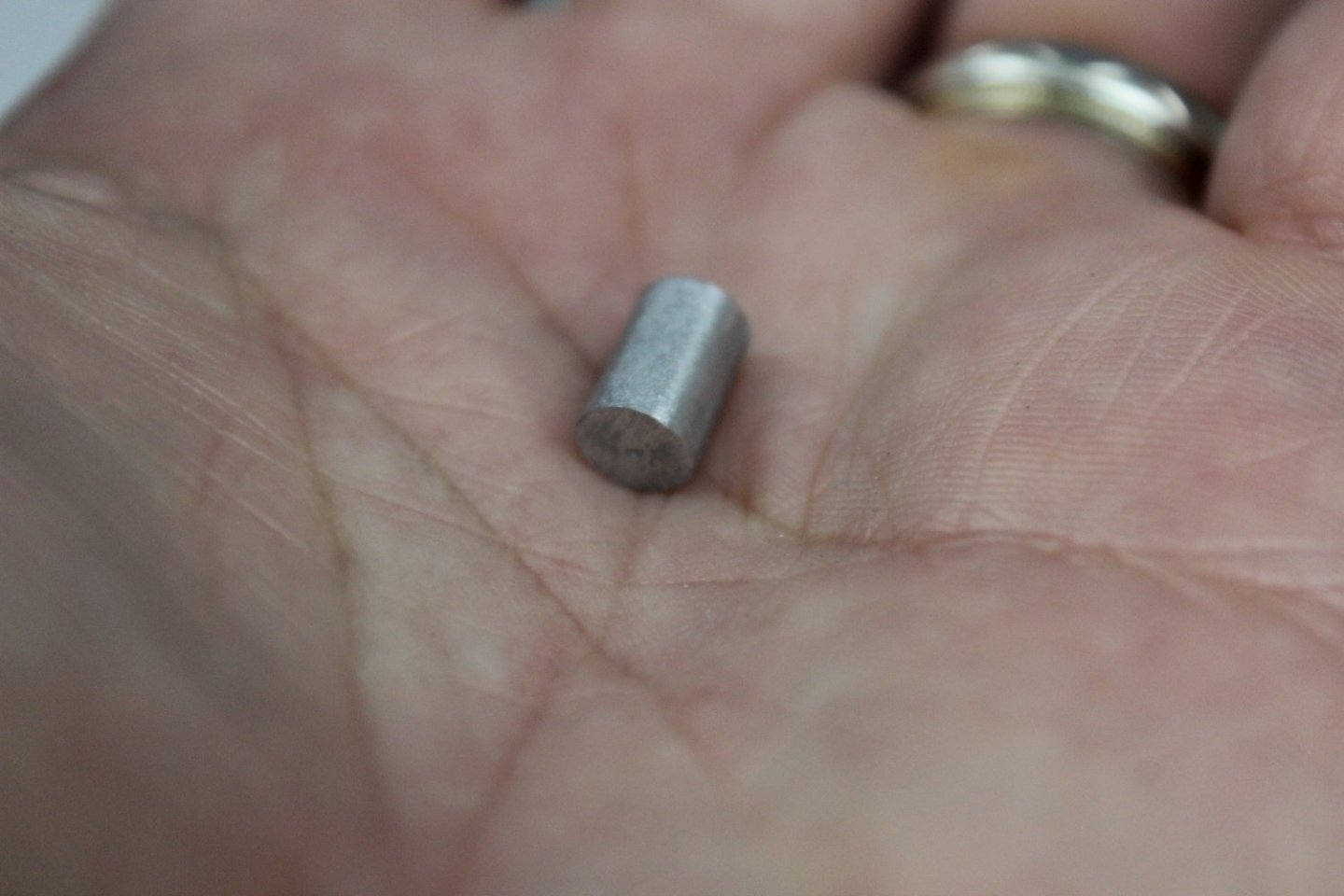
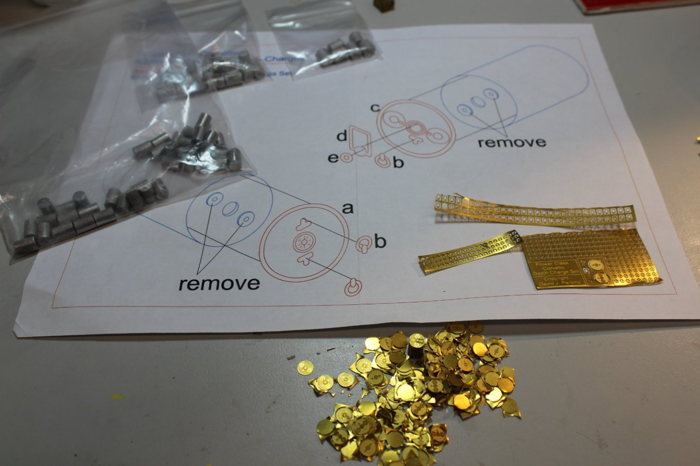
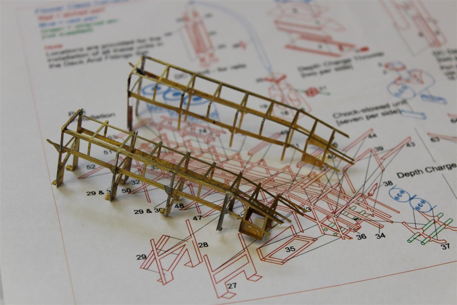
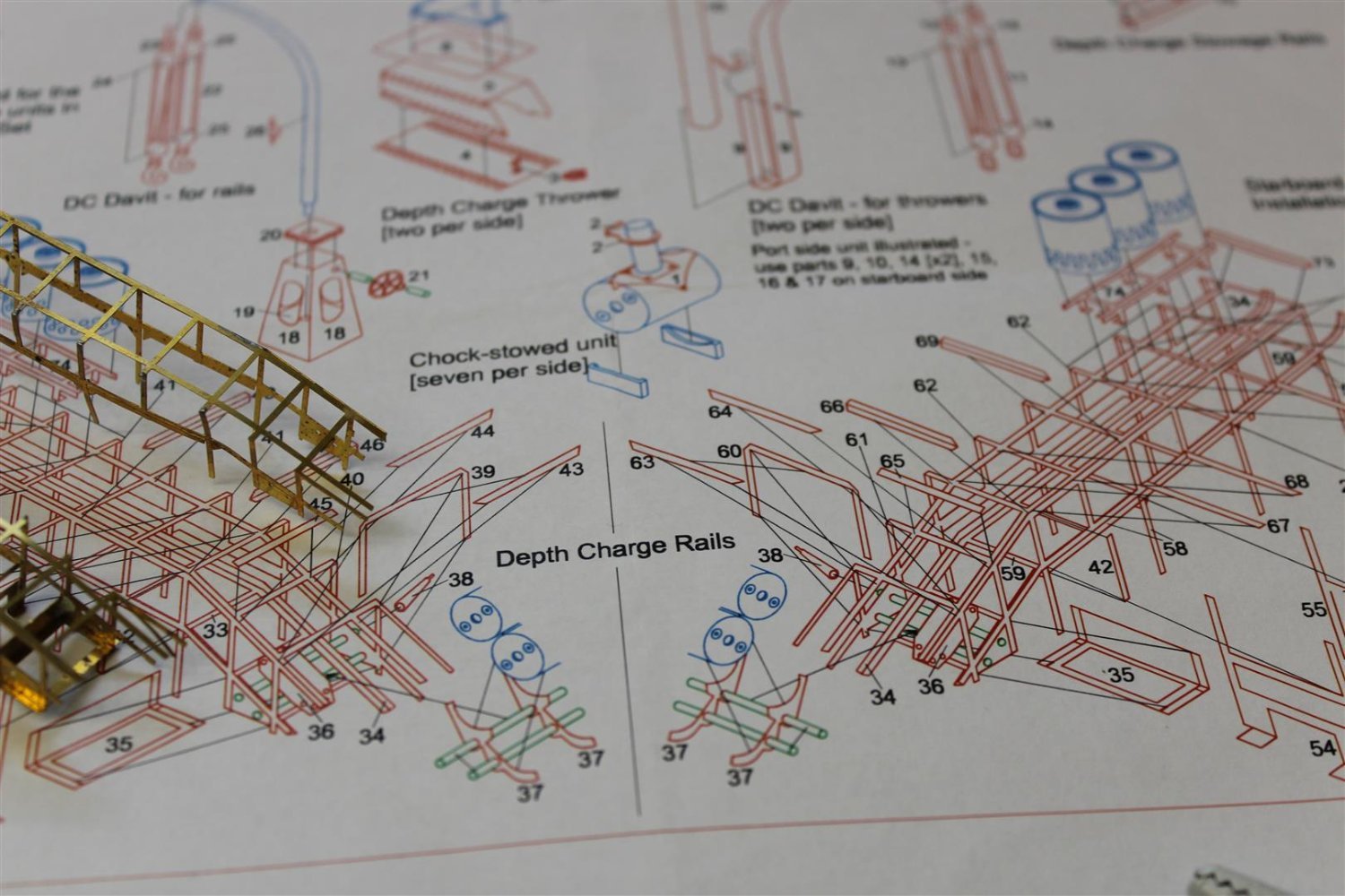
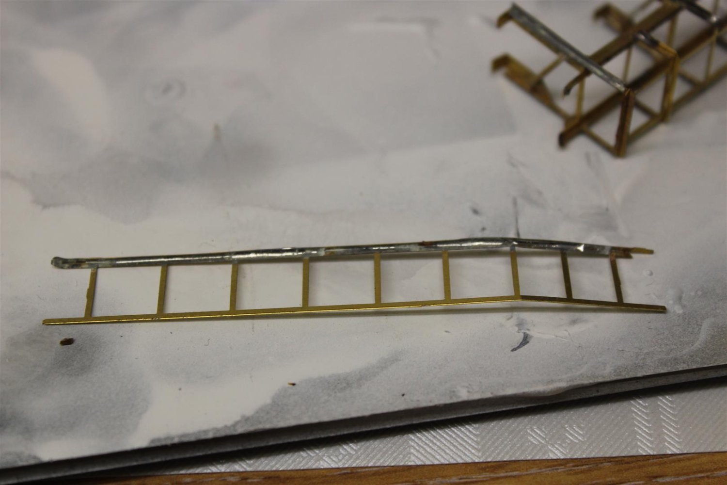
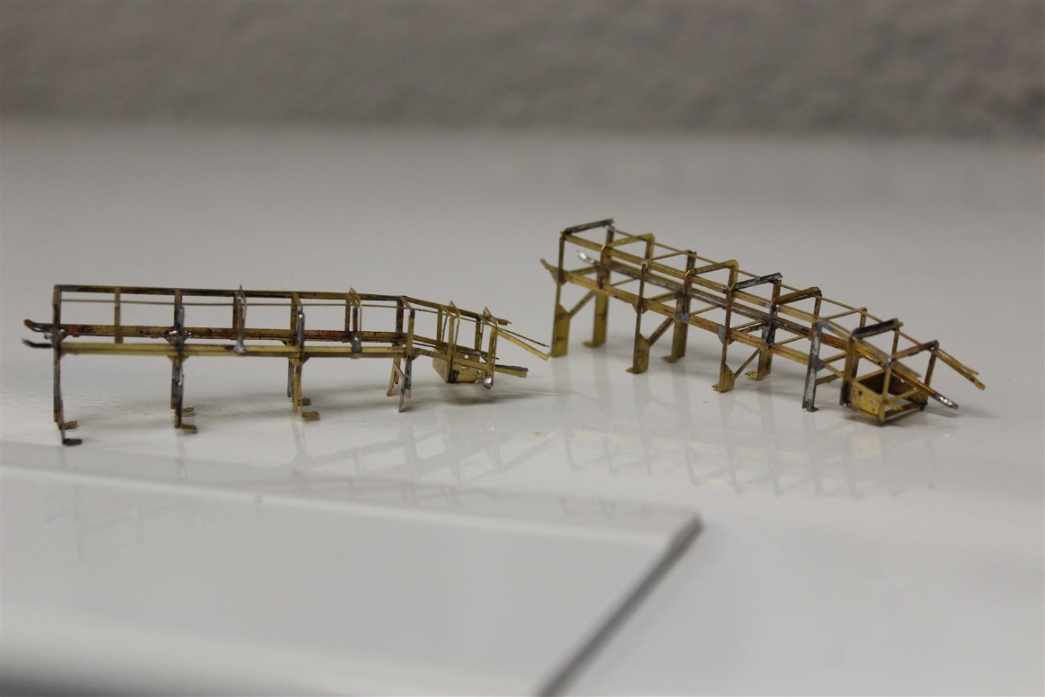
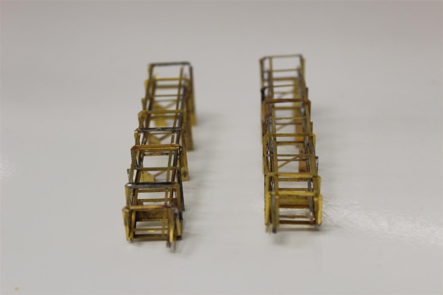
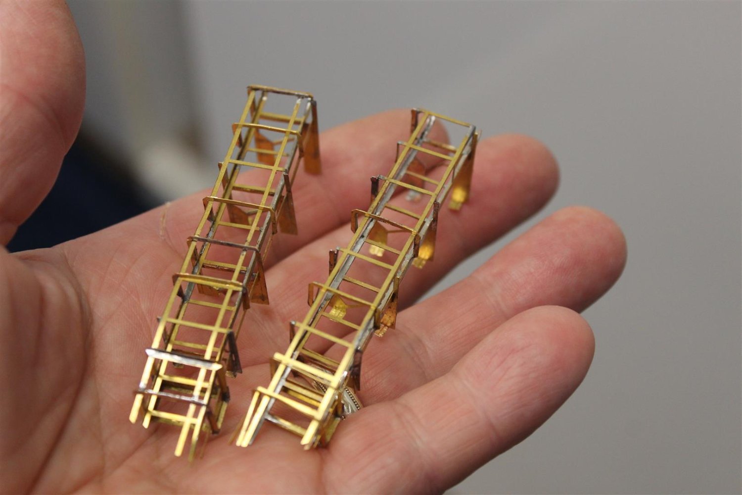
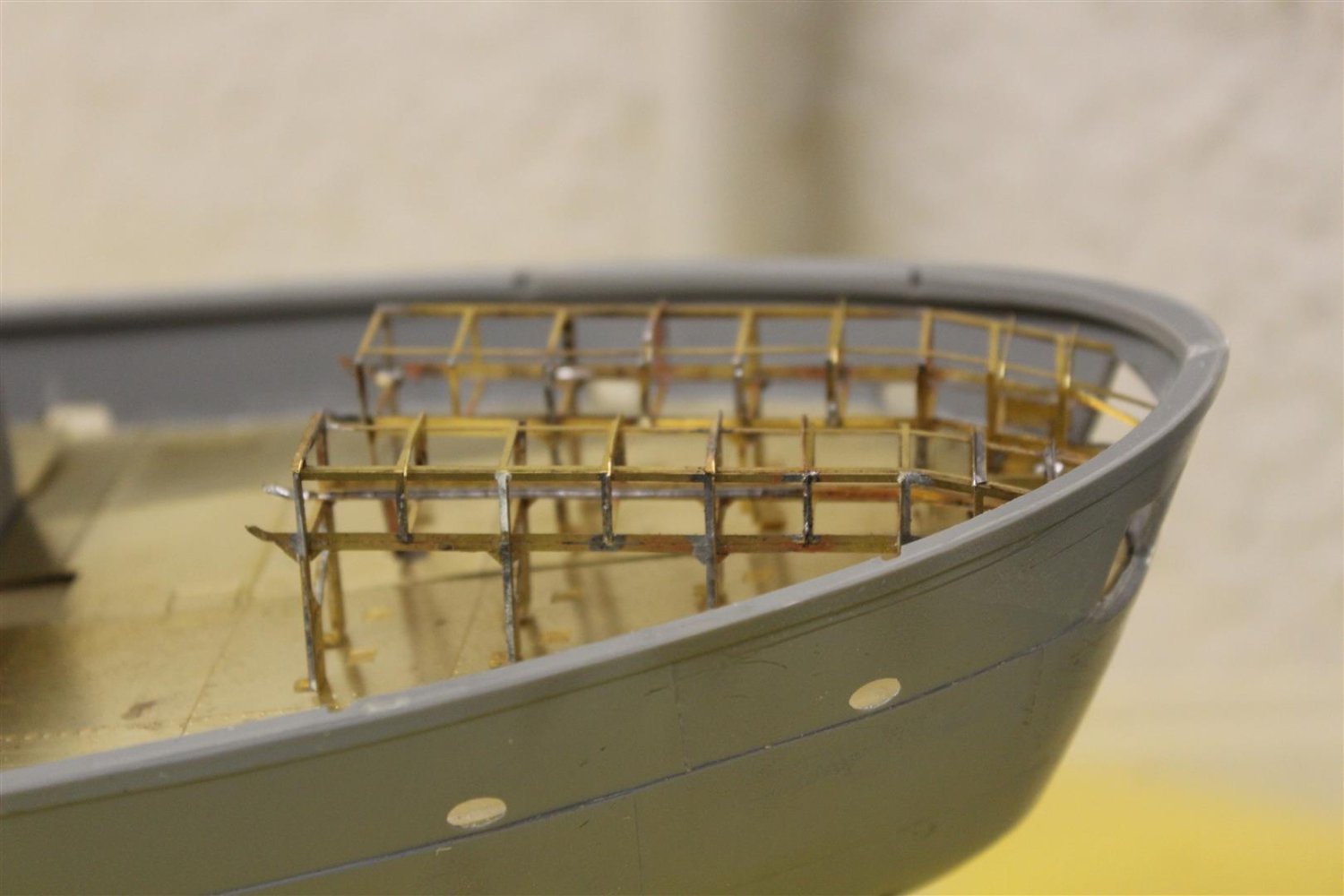
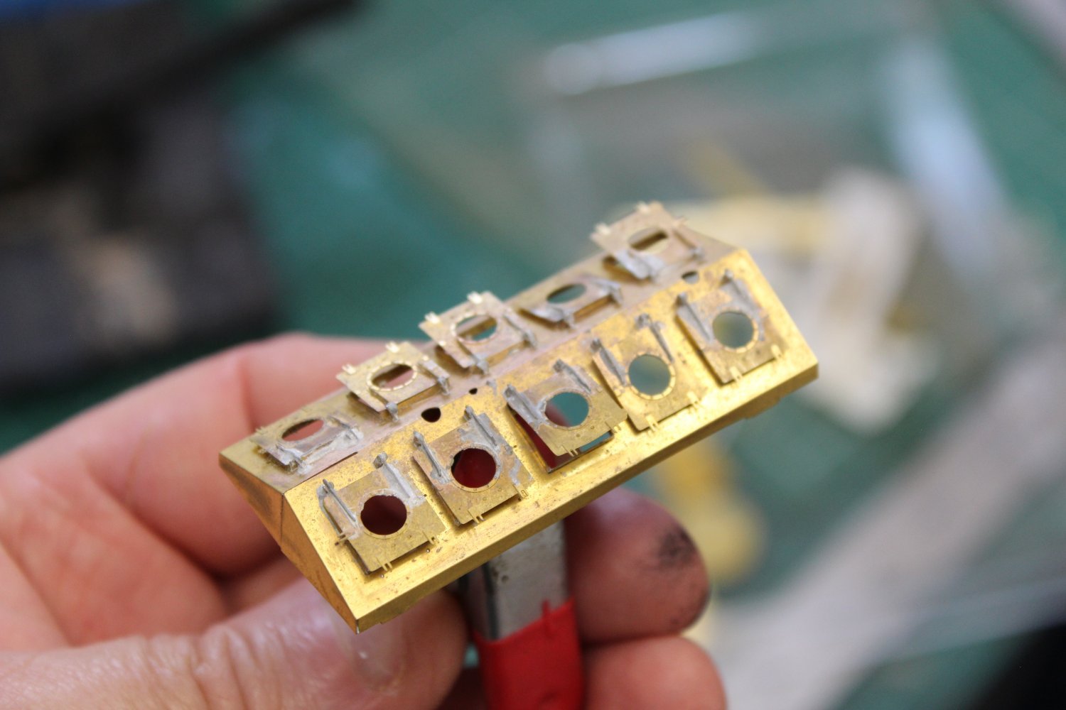
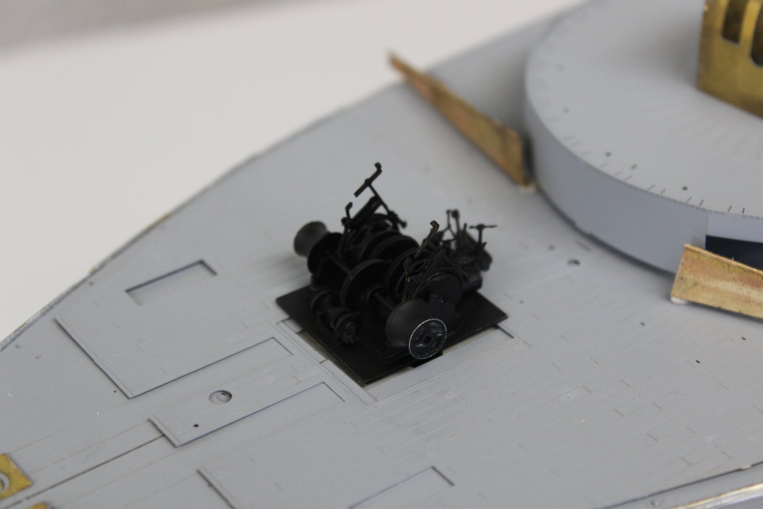
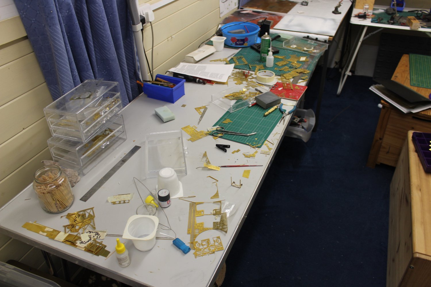
onto the Bluebell, and the depth charge racks, there is more PE on these two units than on lots of extra detail sets, but it is starting to look ok
i have about 40 pieces left to add


-
lovely to see how the experts do it
- Keith Black, ccoyle, Canute and 6 others
-
 9
9
-
lovely to catch up on your log again, you have made such a fantastic job on her so far
- mort stoll and Keith Black
-
2
-
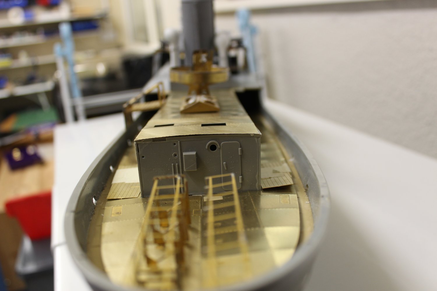
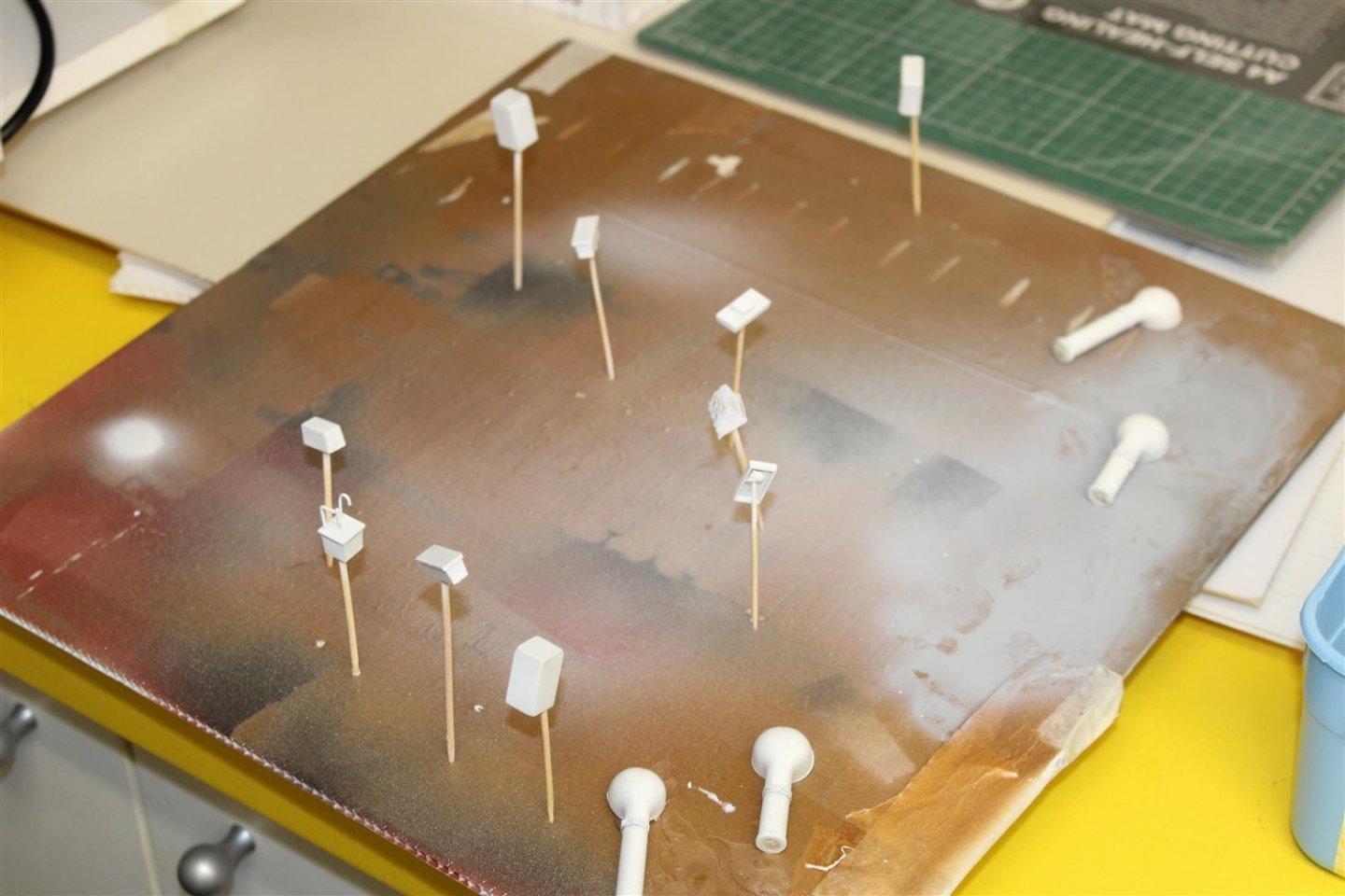
Good afternoon everyone
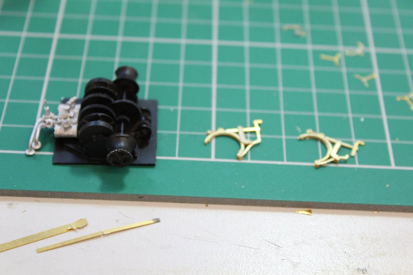
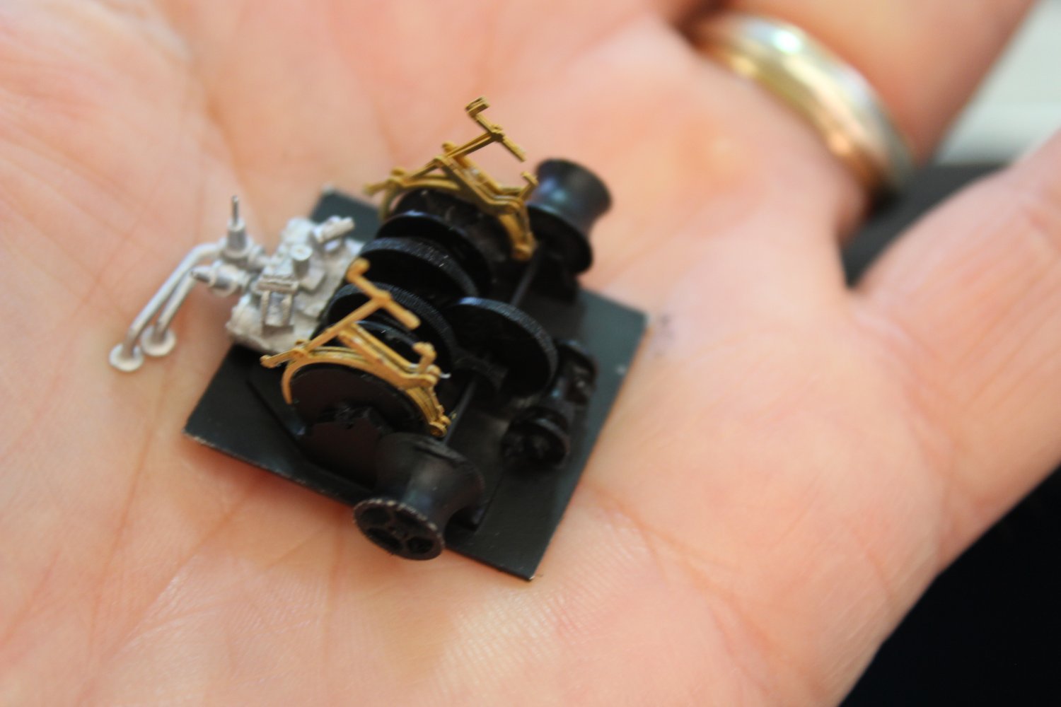
well the anchor windlass is done now and has a coat of black primer on it, i love this GLS PE
primer has gone on to more of the completed bits, like the engine room skylight
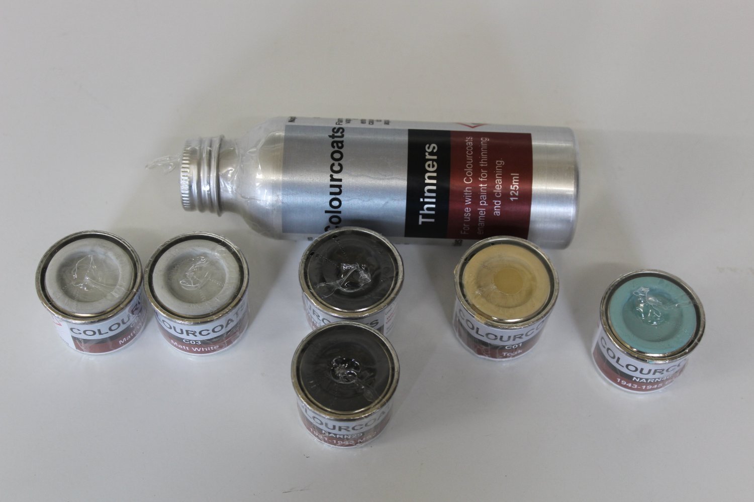
new paints arrived, colourcoats, by Soveriegn hobbies, these will be her going out clothes

some of the PE bits i had done in the past had a powdery finish, cleaned up with my tooth brush


-
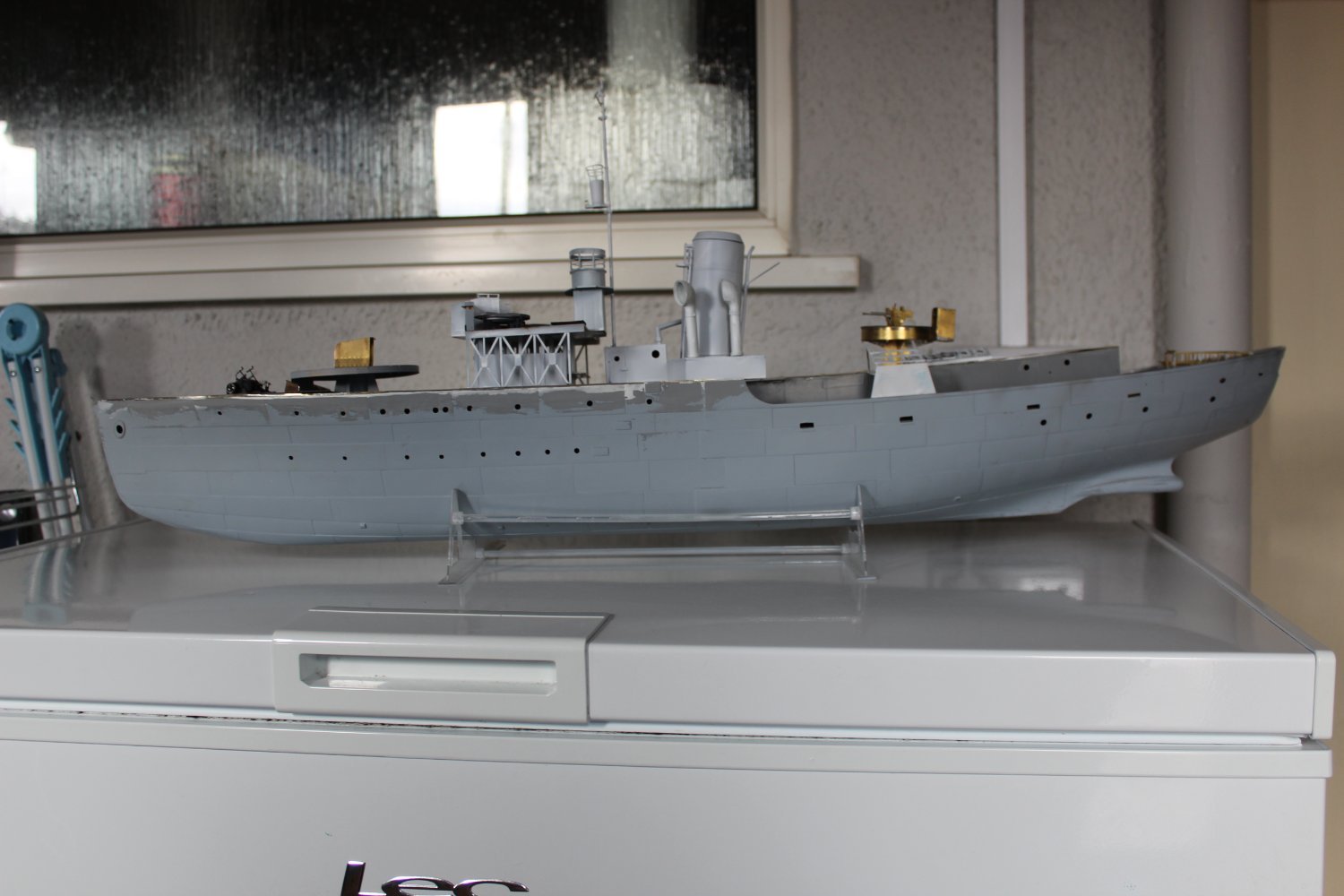
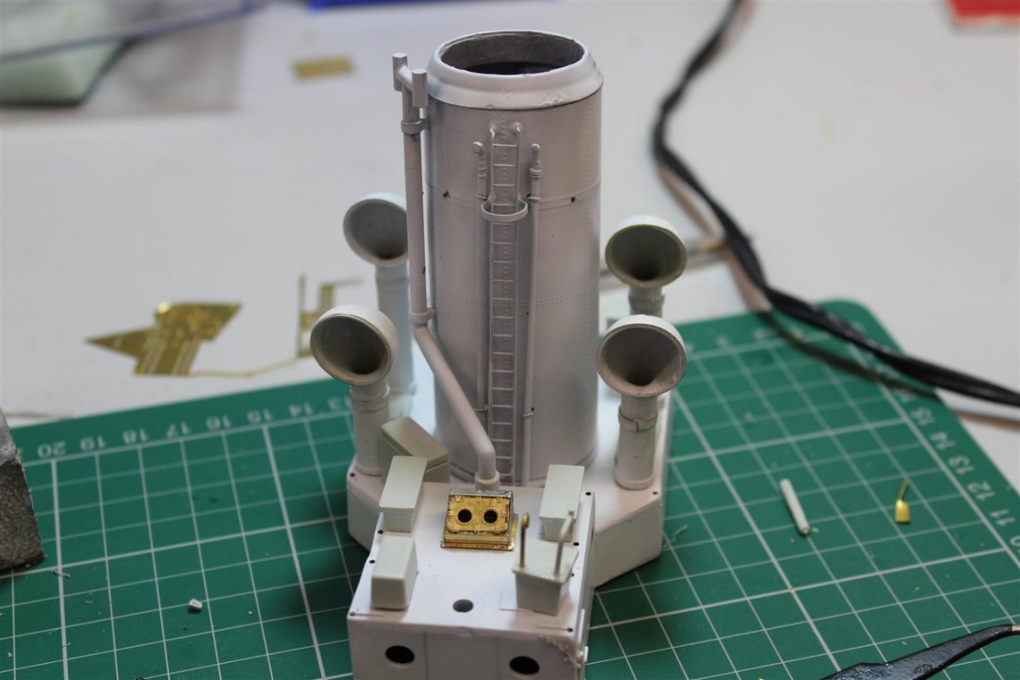
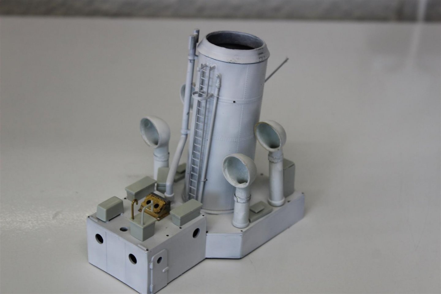
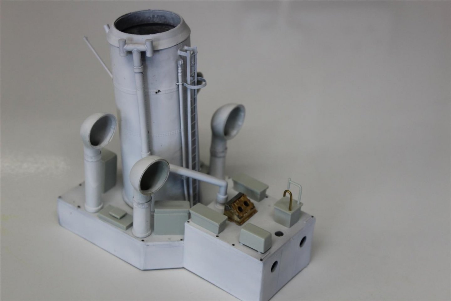
good evening everyone
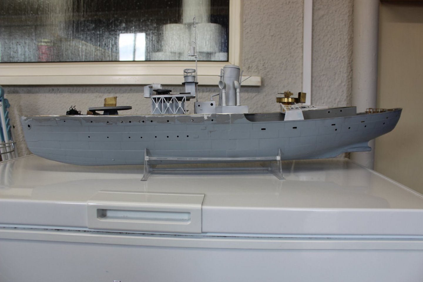
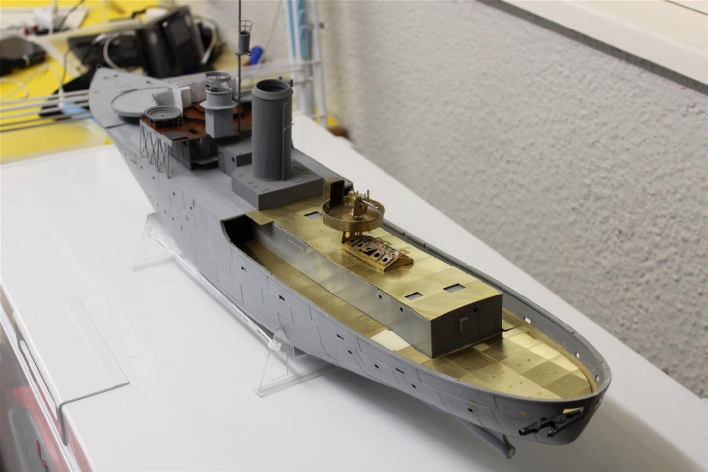
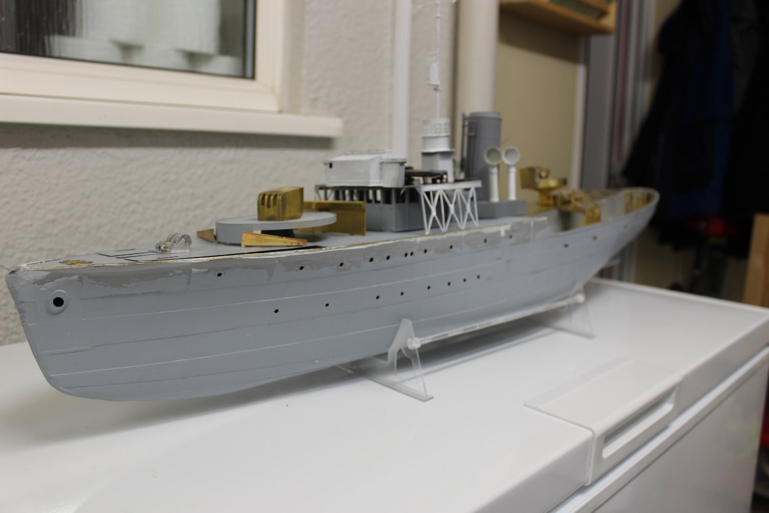
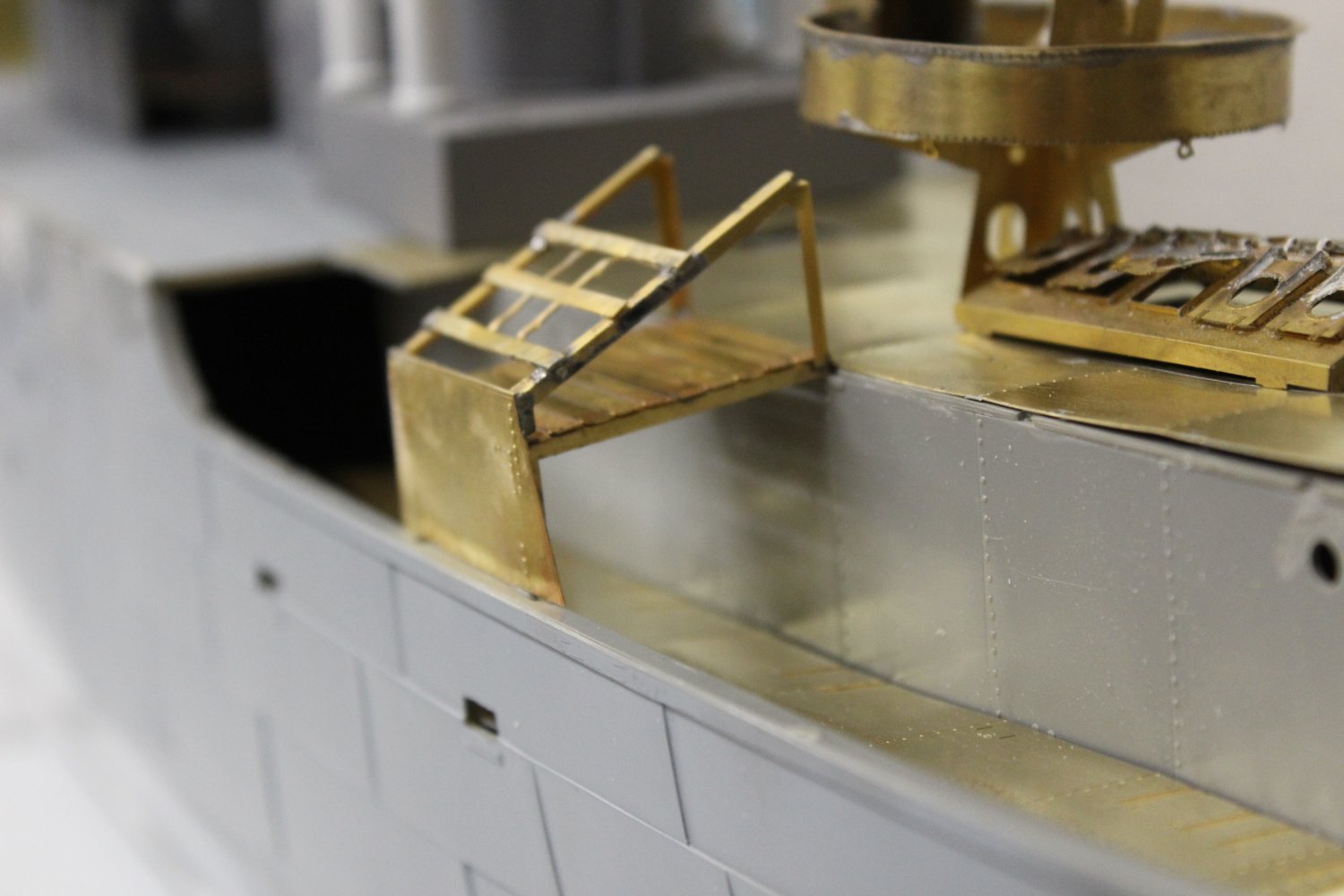
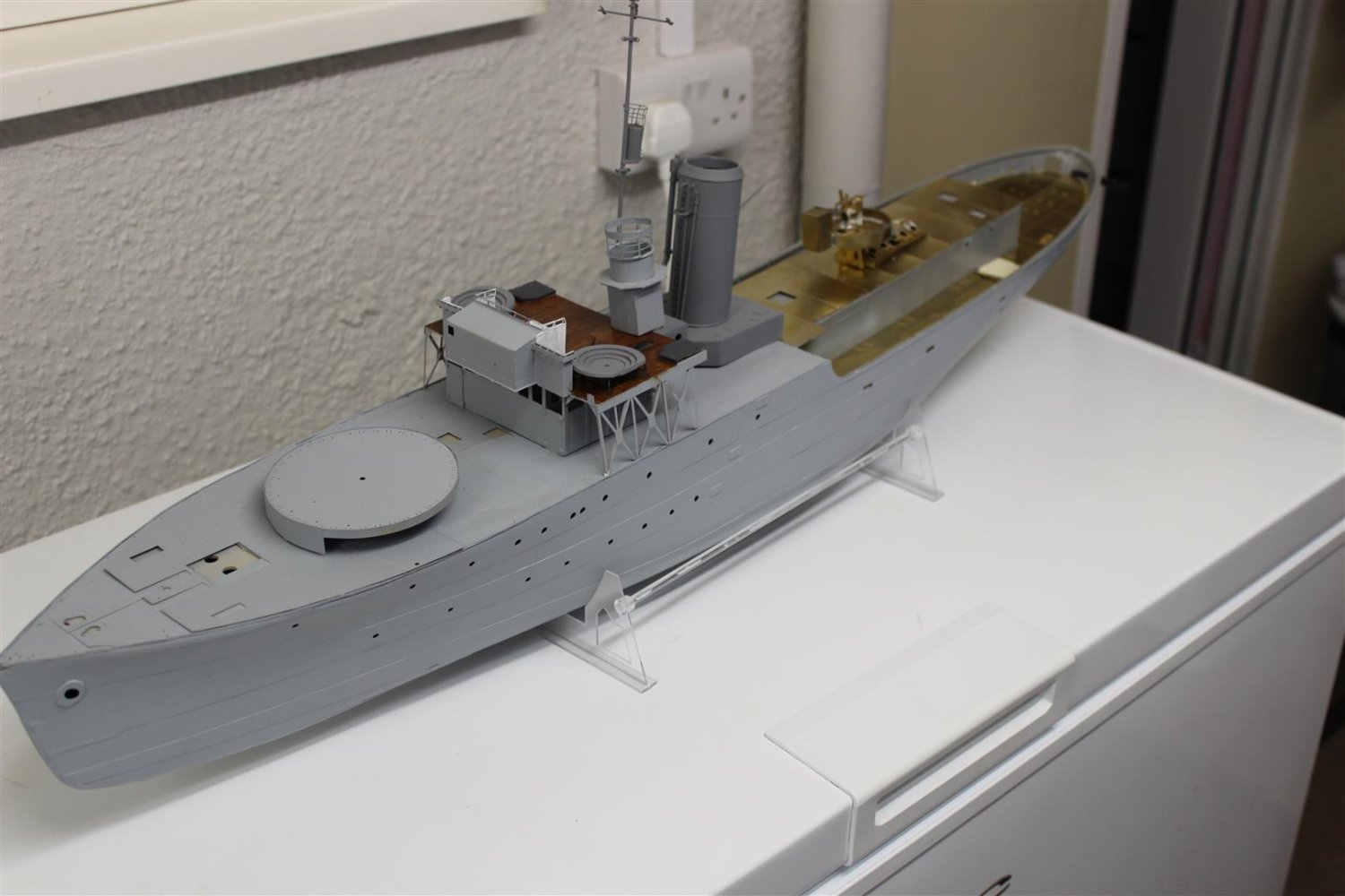
HMS Bluebell work continues, but slowly
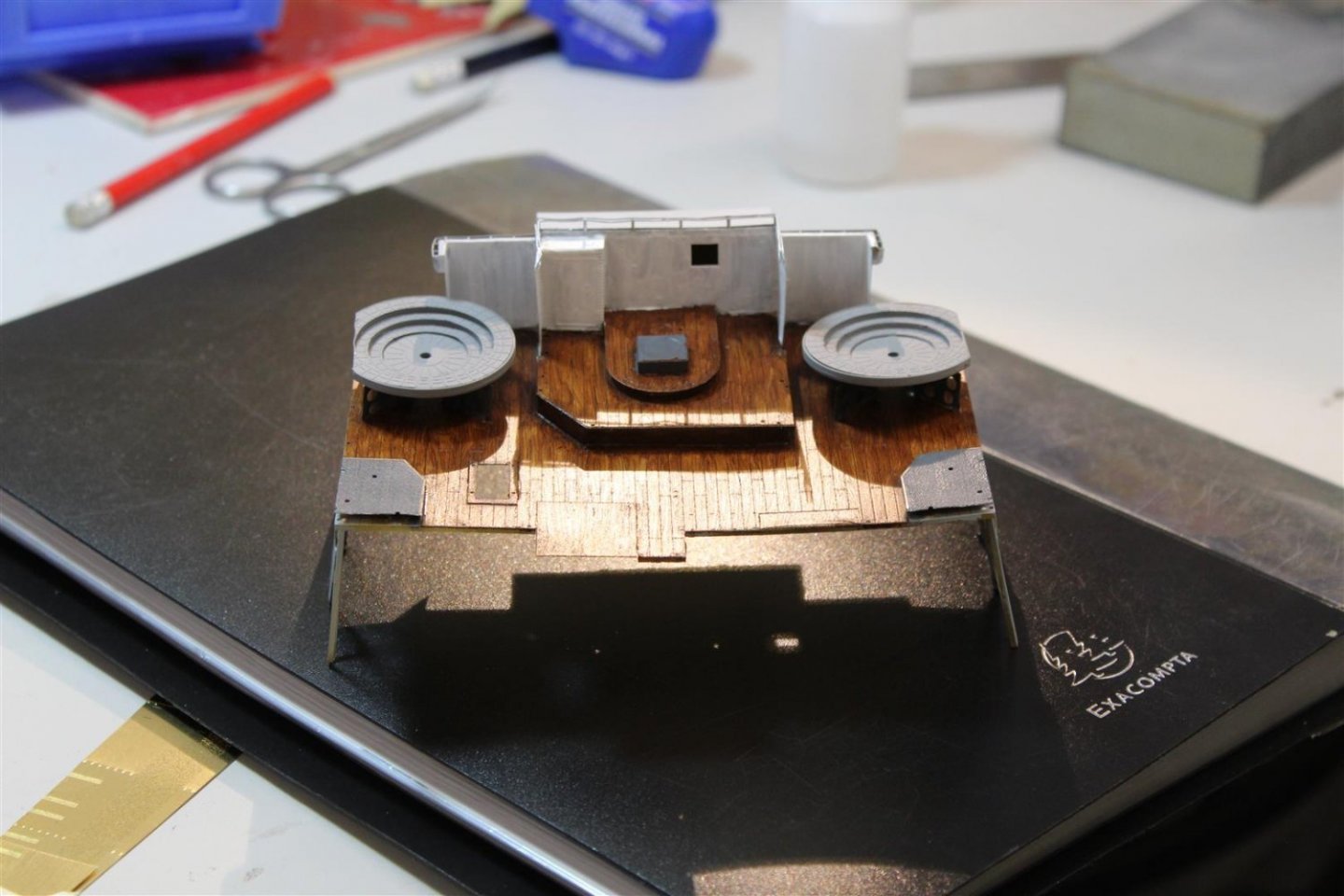
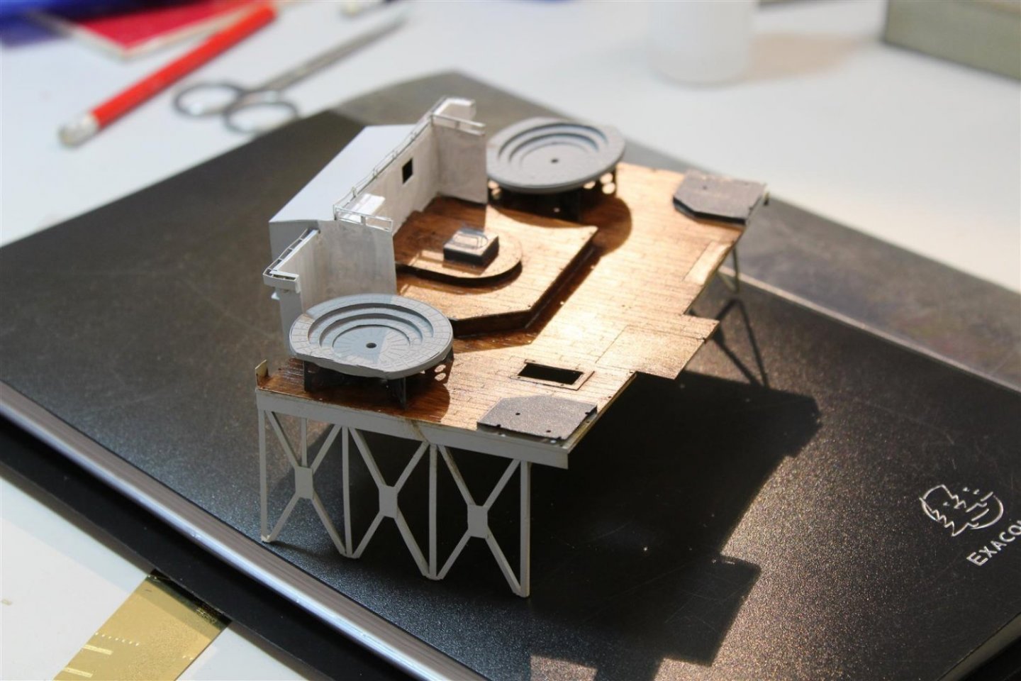
soldering takes me forever, but today I managed to make up one of the Carley float unit, and the breakwaters,
work continues to blend the top deck with the hull, but it looks so much better than a few days ago
i have a paint order coming in from Sovereign hobbies, then most of the vessel will go to white
loads of photo etch still to make up
nothing is fixed into position yet


- Old Collingwood, bruce d, Canute and 7 others
-
10
-
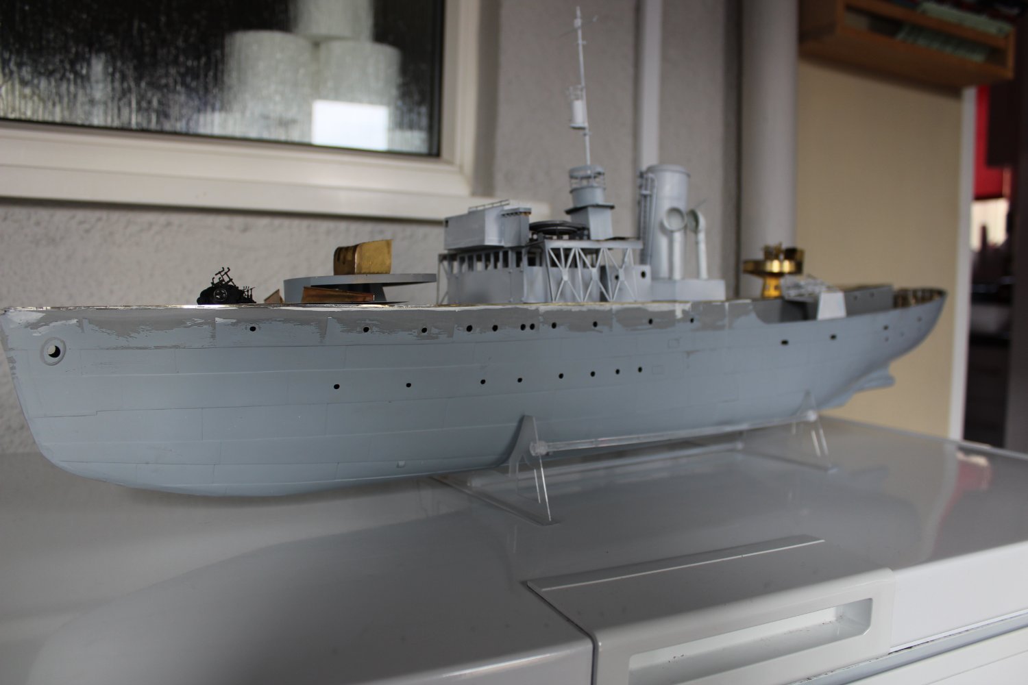
good evening everyone
thank you for comments and likes
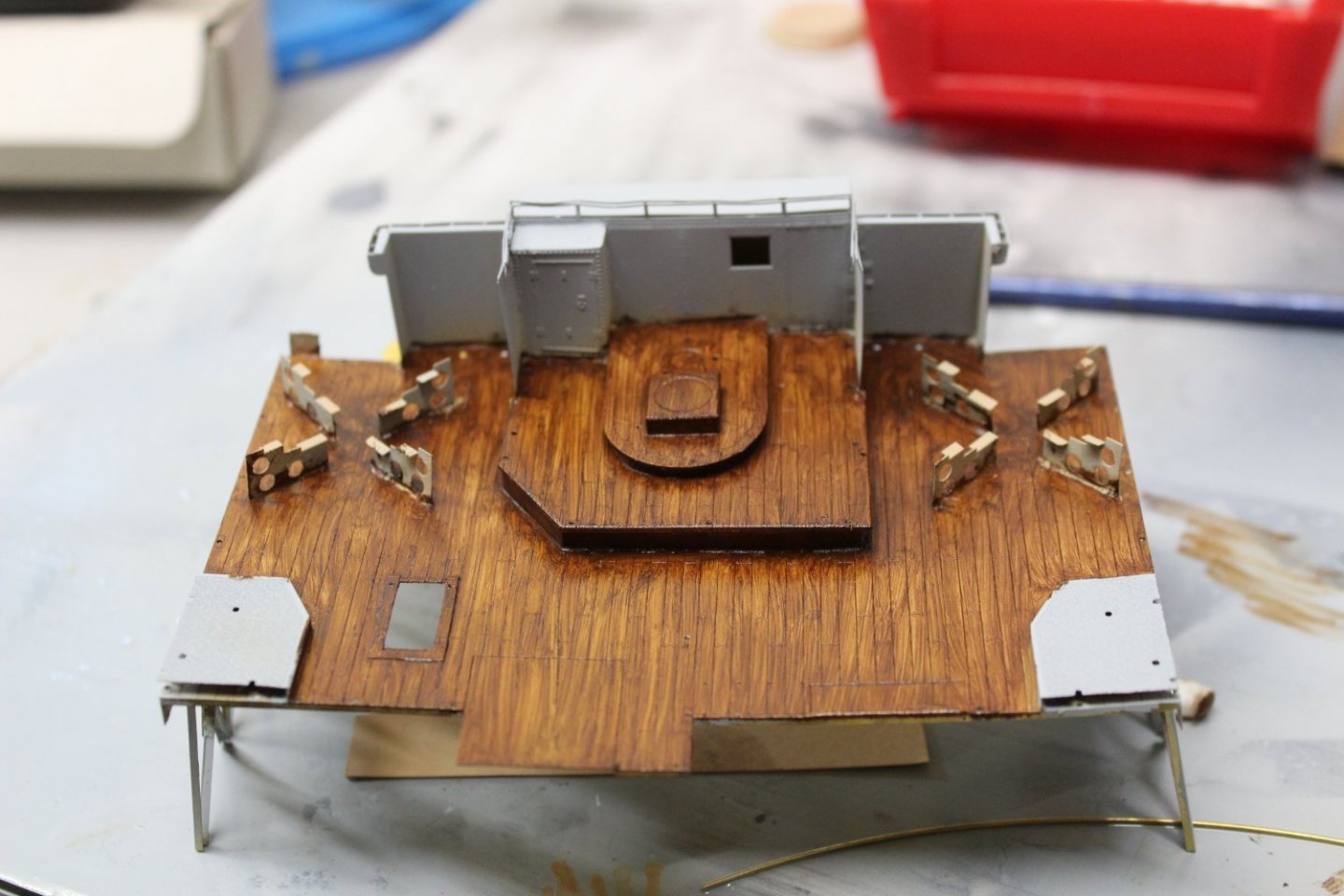
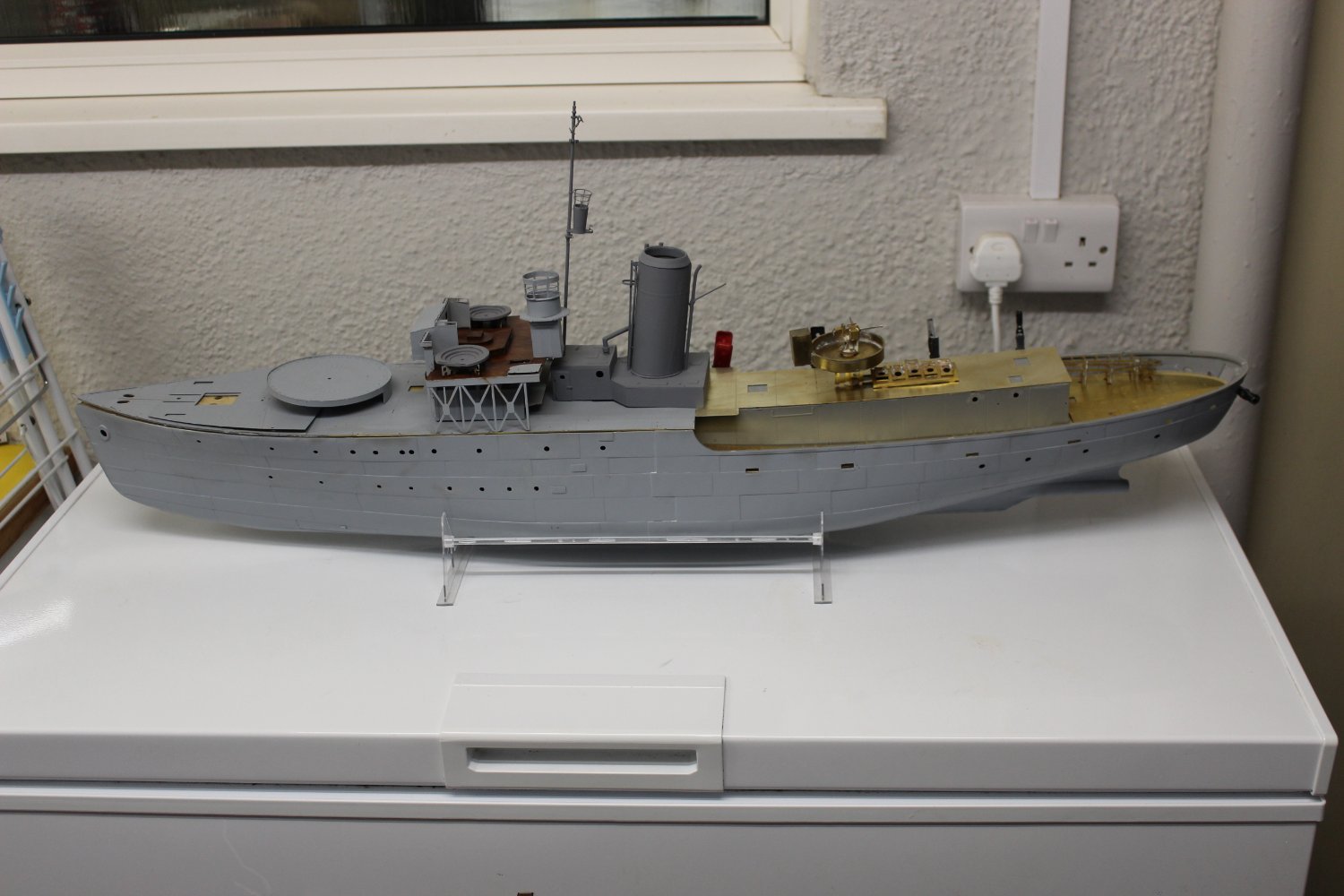
more progress made on the build
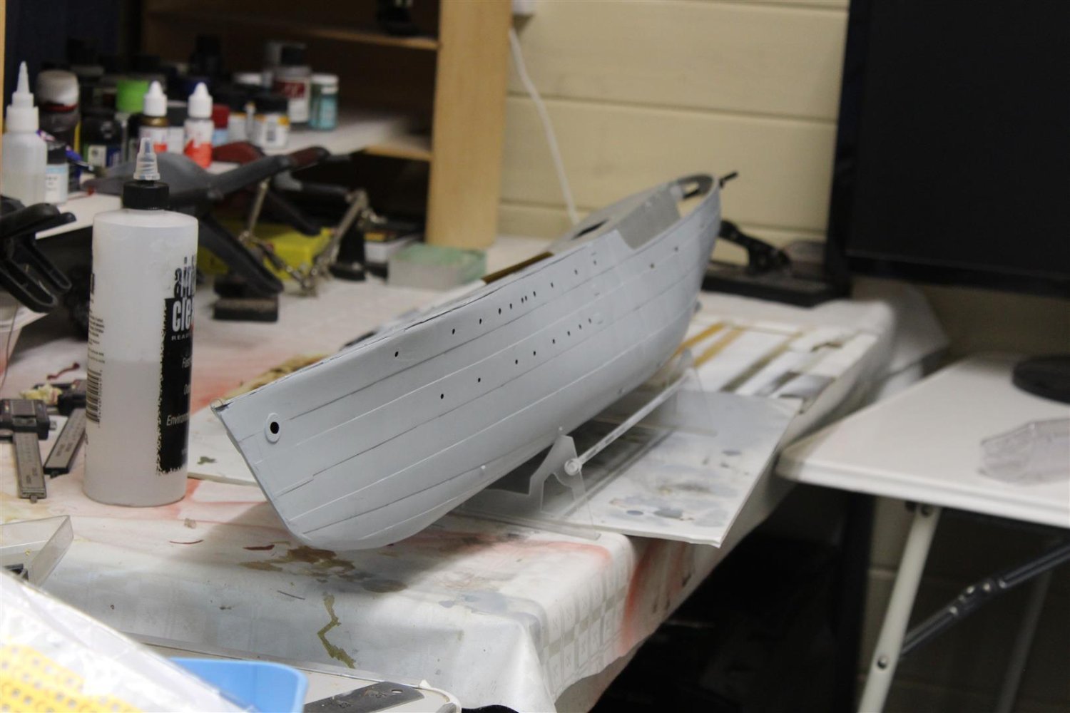
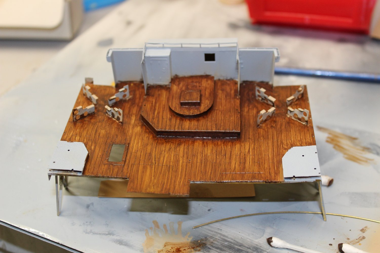
the forecastle is now fixed into position, i need a bit of filler to match it to the ships side
more work done on the bridge, yes the wood is to dark, i like it, i will get the rest to look a bit more like teak
all the rivet markings have now been done, thats about 300 i did today
i am now awaiting a callout for the Western approaches colours


-
good evening everyone
thank you for comments messages and likes
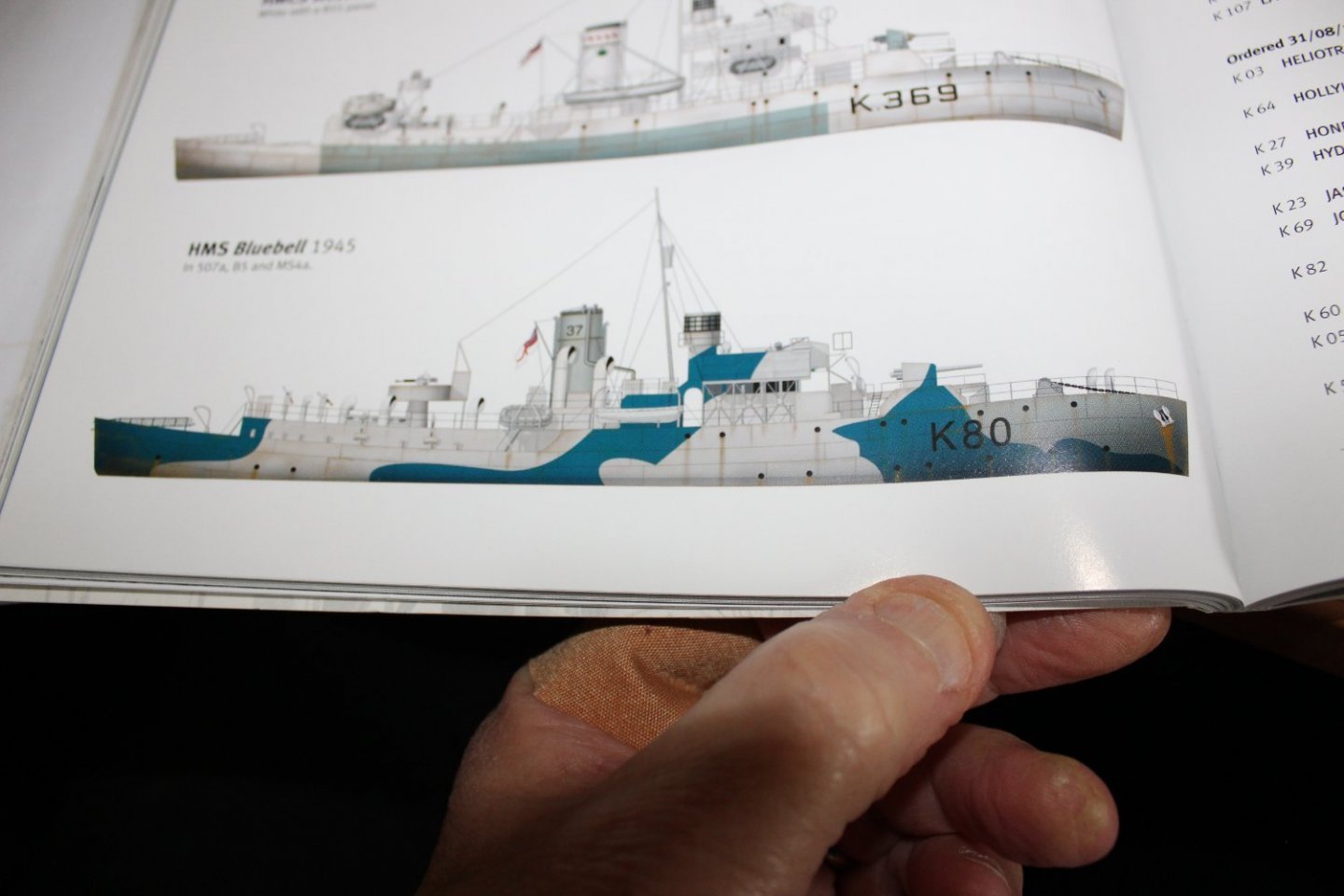
well the dust has settled from the builds fiasco, hopefully how i can get on and complete something
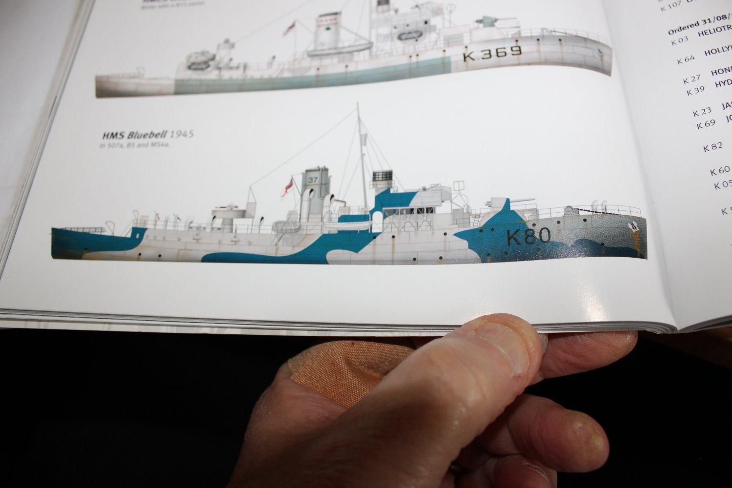
i have been talking to Sovereign Hobbies about the paint scheme, it seams the book i am, going by is wrong in the colour call out, i was after a western approaches 1945 scheme with a dark blue, the colours listed
507a
B5
MS4a
were never used together, as an official scheme
-
good afternoon everyone
been a crap week model making wise, loosing the SD14 and then abandoning the POW, but that's just modelling, for others there are far more important things in life to worry about
i have brought the Bluebell back to the bench, took me a few hours to get back into it, the biggest difference between when it was put away and now is the airbrush
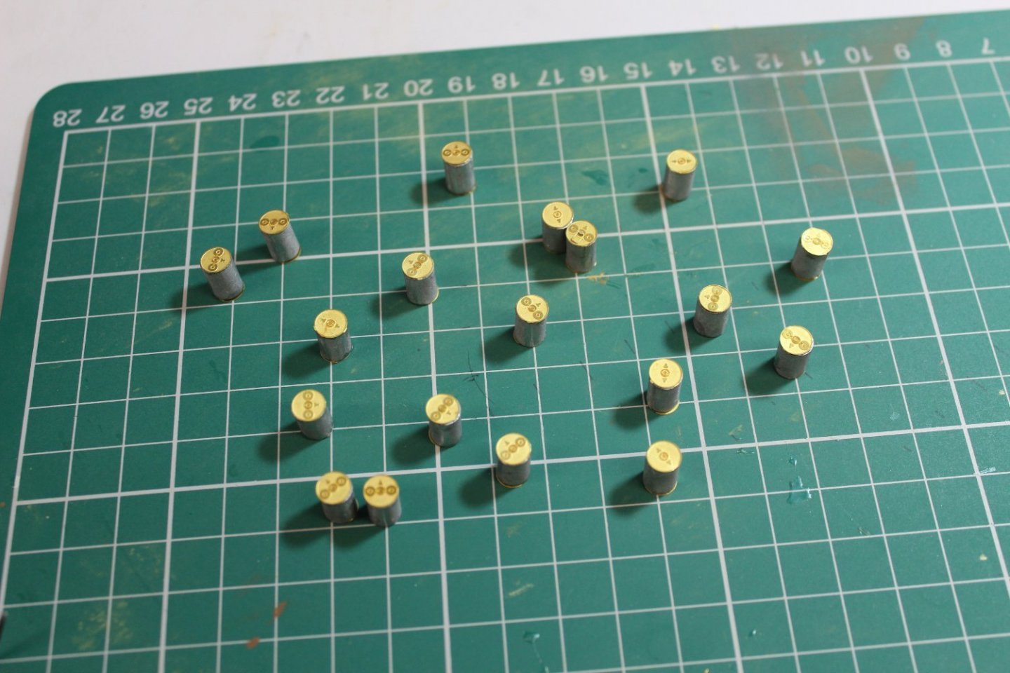
made up a few depth charges, and played with some wood effect,


-
1 hour ago, dancooper said:
I'm so sorry to hear that, but I as well do understand. However I hope you are still going to continue working on her off grid... maybe when you are in a later phase you might still share pictures.
off grid maybe it certainly is not going to landfill, it's not terrible, just not a standard i wish to share
,
-
-
4 hours ago, allanyed said:
Interesting subject Kevin. I remember studying these ships in the Naval Architecture class and wish I still had my old books, but do not recall this subject (it has been close to 60 years) I did find this paper which is quite interesting but see nothing about the rudder design to help you, sorry. https://ww2.eagle.org/content/dam/eagle/publications/company-information/workhorse-of-the-fleet-2019.pdf
thank you, i will read that when i get a chance
-
2 hours ago, Roger Pellett said:
Kevin,
That’s called a ContraGuide rudder. It is shaped that way to straighten flow from the propeller.
The propeller works by accelerating a column of water behind the ship. The reaction to this column of water, Newton’s Third Law, is a force in the opposite direction that pushes the ship ahead. Water, however, is viscous and this viscosity causes the water in the column from the propeller to rotate. This rotation is lost energy. The offsets on the rudder are intended to introduce a vector opposite to that of the rotating water column, to recover the lost energy.
Roger
thank you,
rereading the reply it wasnt two rudders then with independent movement, it was two welded together offset
so how was this solved,
was it better propeller design, two props, twin rudders?
-
Just now, ccoyle said:
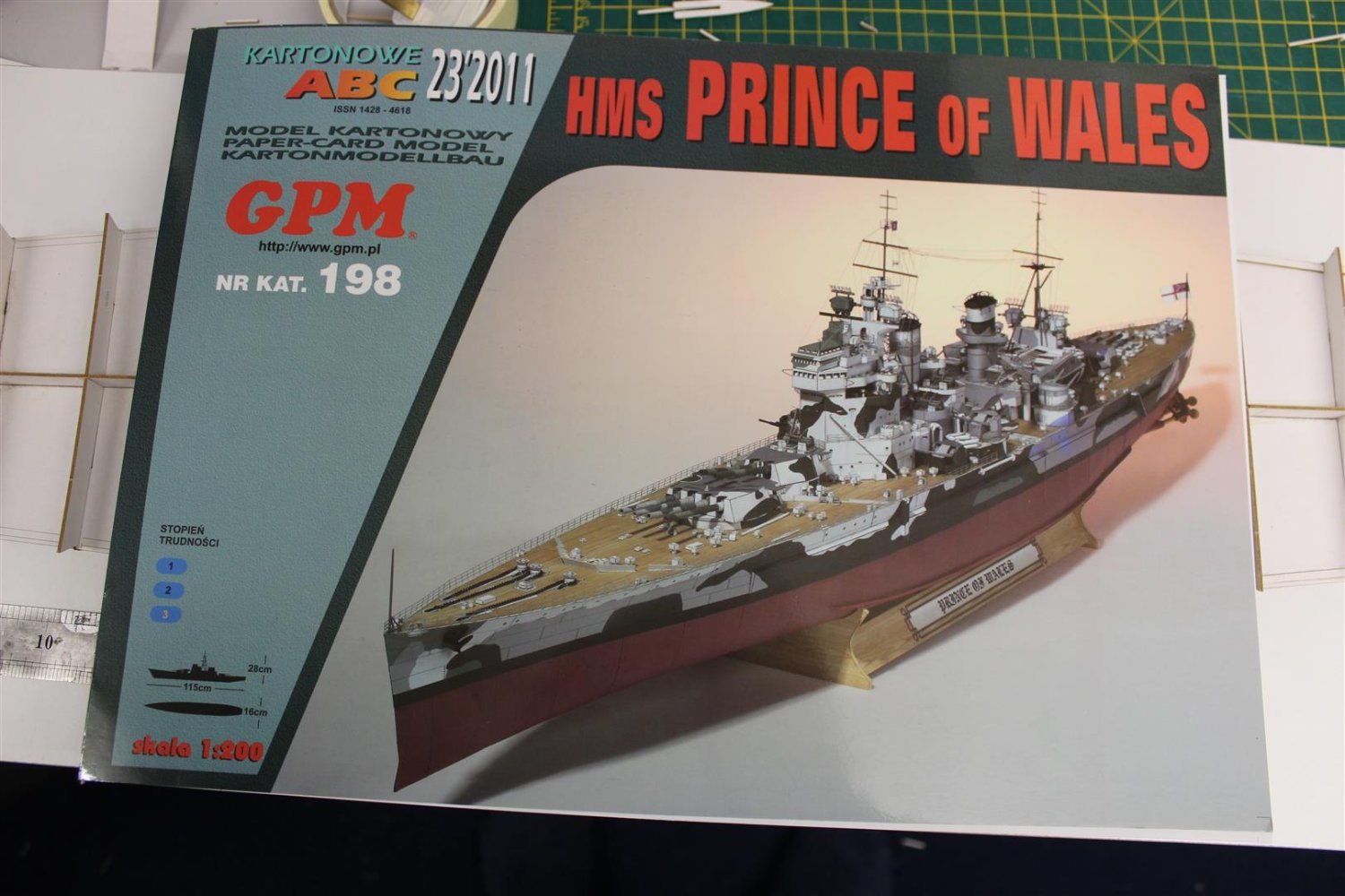
Looks like the kit artwork includes some subtle weathering.
yes it does, and its not over the top, lol it hides my mistakes
- lmagna, Canute, Old Collingwood and 2 others
-
5
-
Good evening everyone
day 3/71
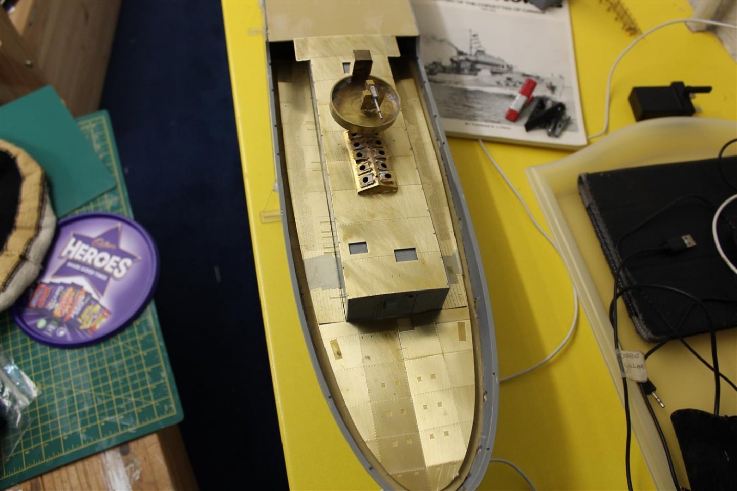
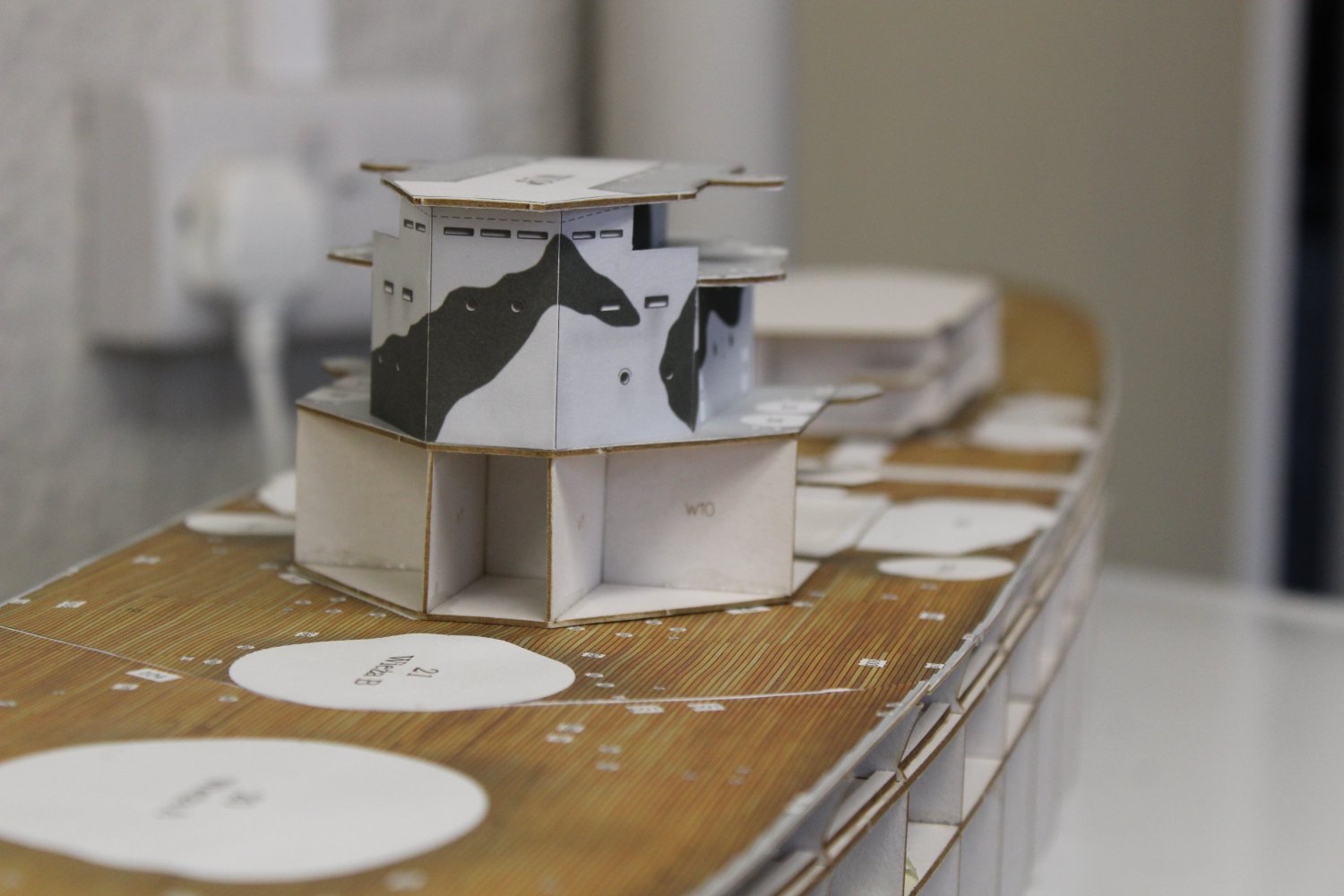
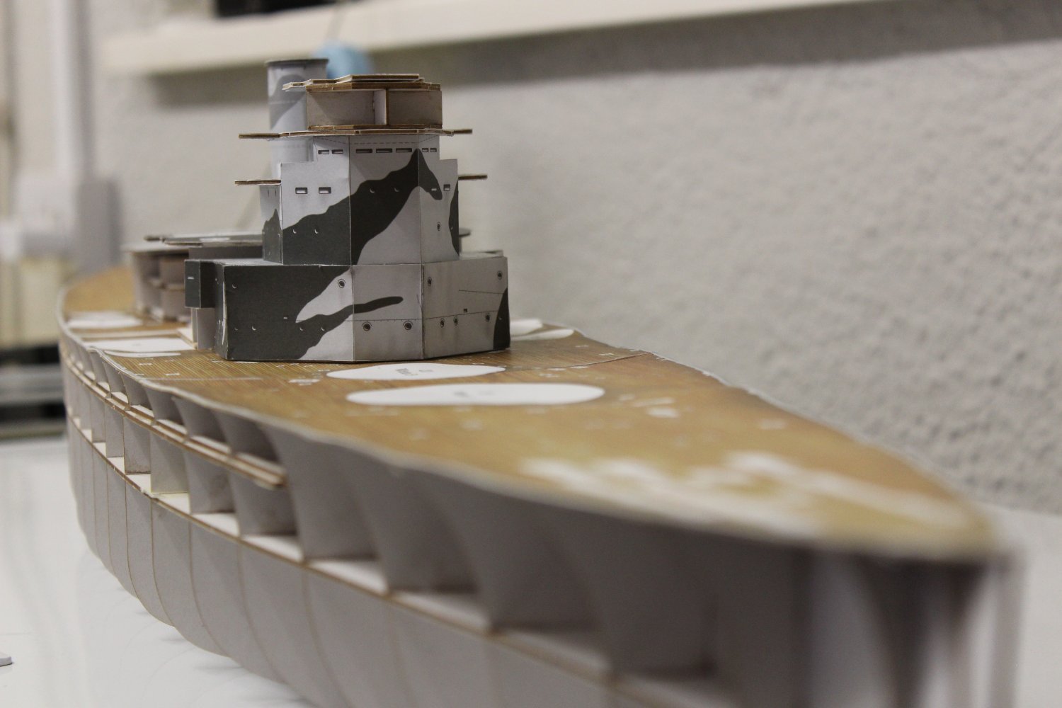
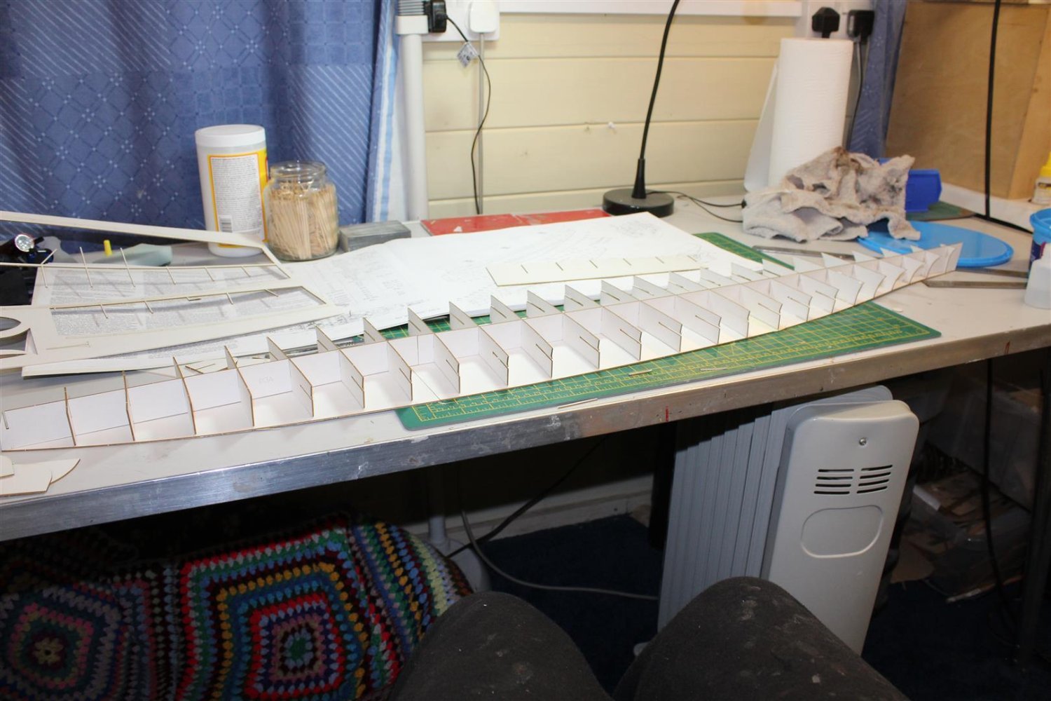
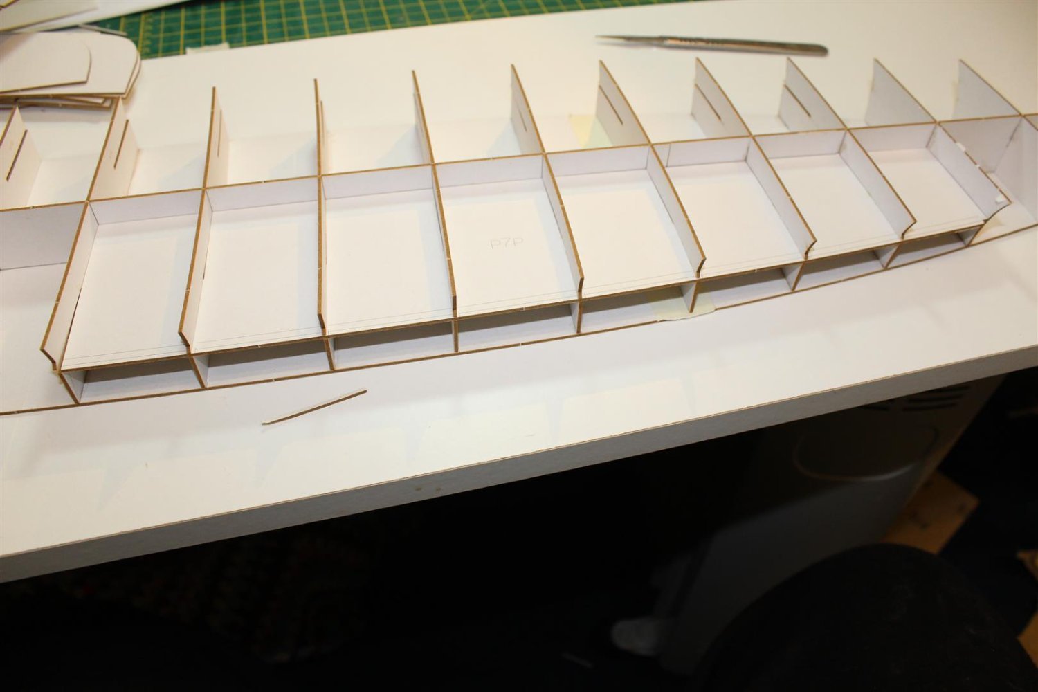
well i certainly would not recommend this kit to myself as a starter kit, its requires completely different skillsets to anything i have attempted before, and some of the mistakes i have made today reflect the fact i didnt have a clue what i am doing
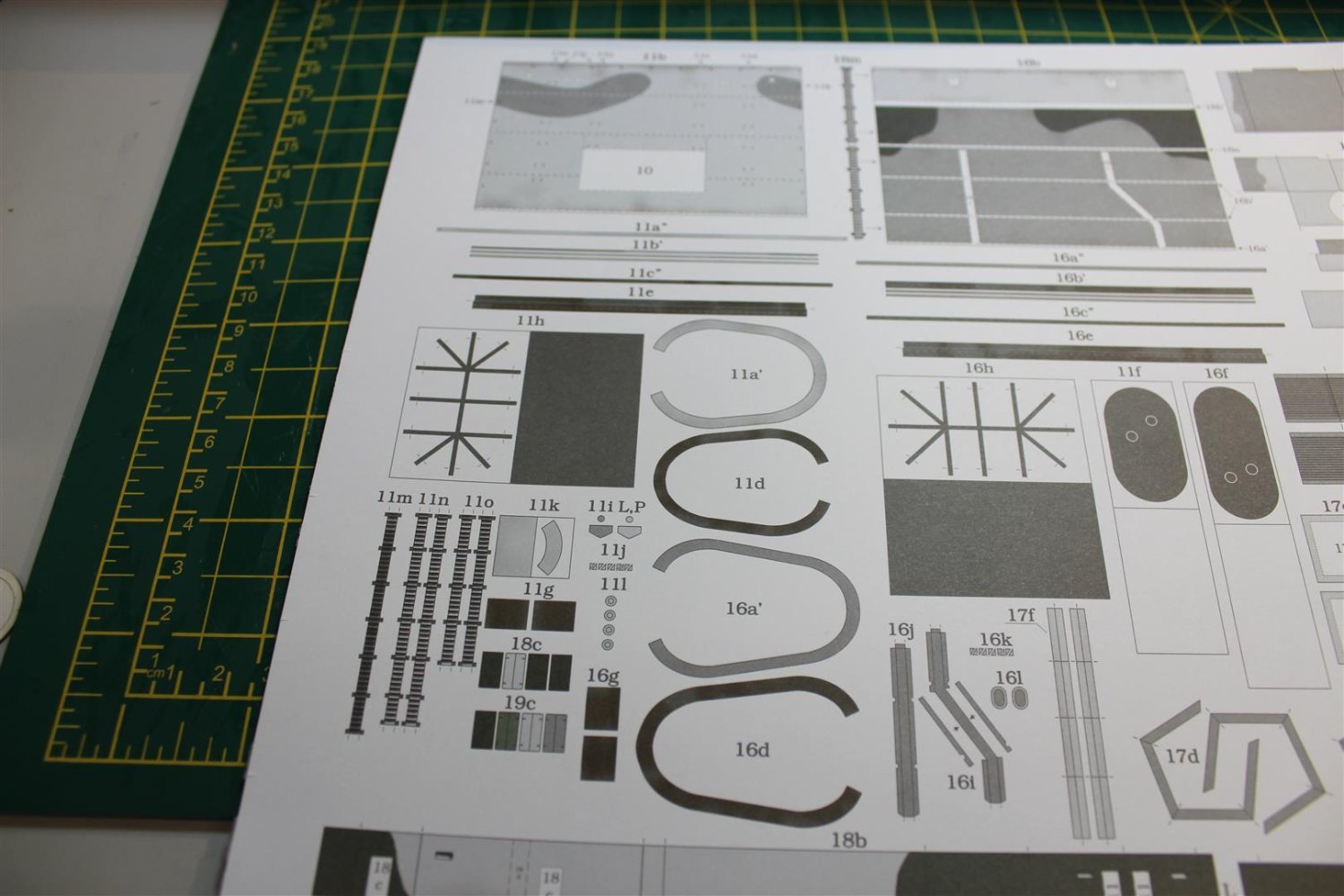
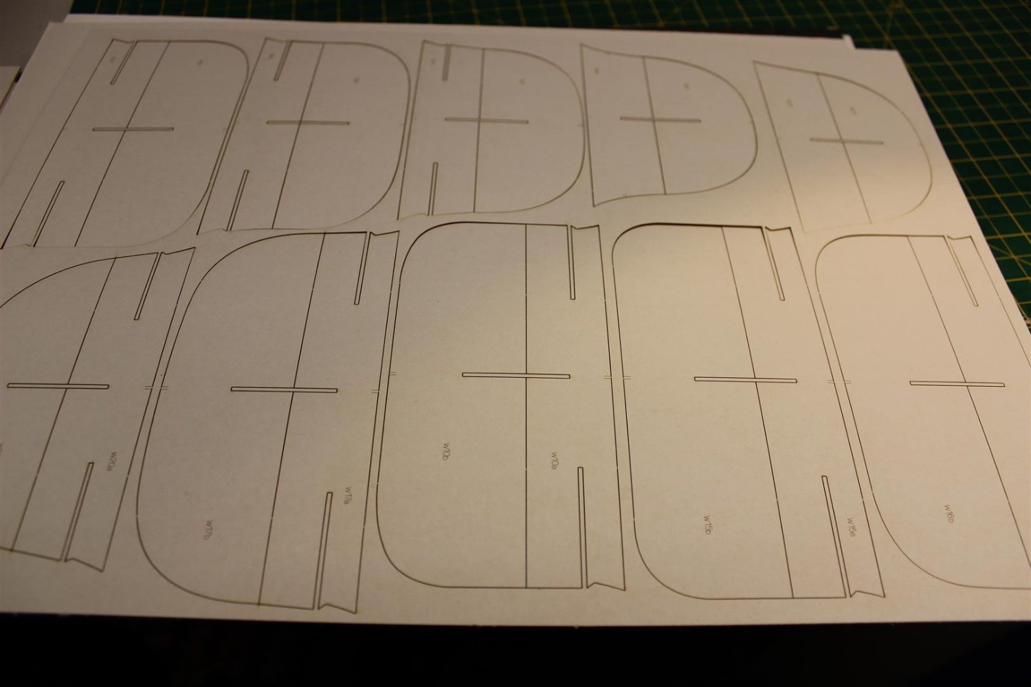
it took me ages to work out that each laser cut card is covered on all sides, if it can be seen, lol i had all these duplicate shapes with different images printed on them
the paper is not forgiving if a mistake is made on folding the crease opens up and exposes the fibres
yep school boy errors, but work continues
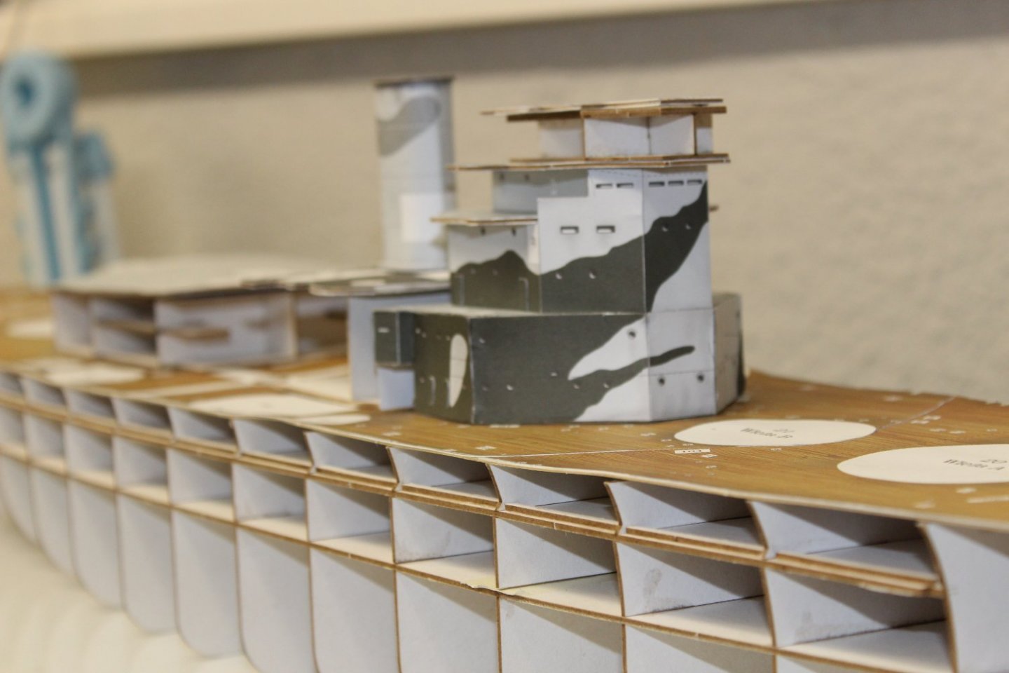
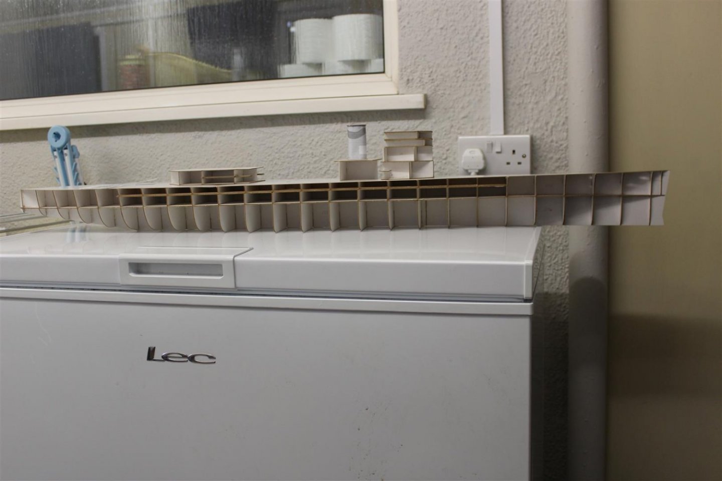
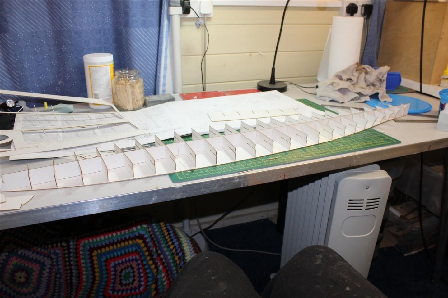
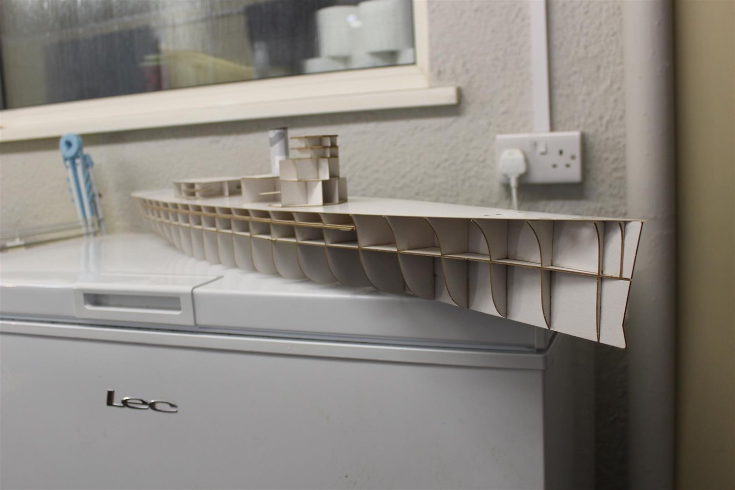
the card top deck is placed on, which stops any twisting in the hull
the printed top deck followed after the glue dries
the rest of the day was spent putting the wrap on wallpaper onto the superstructure, which caused me a few issues


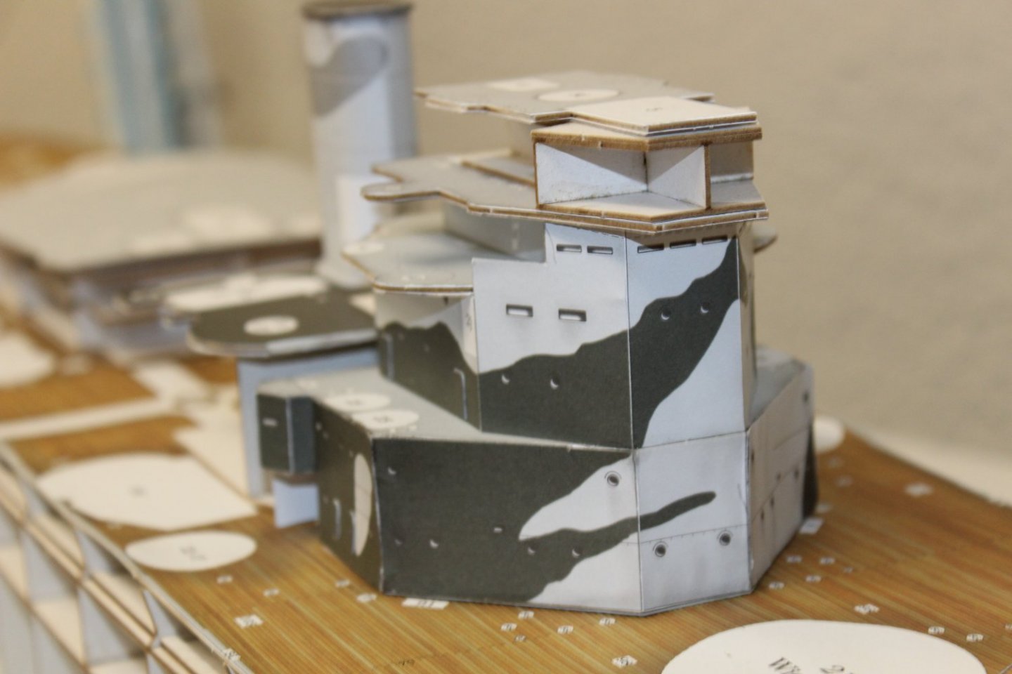
some of the edges look messy, i hope to sort these out somehow


-
-
good evening everyone
thank you for comments and likes, and welcome to new followers (im the guy who never finishes anything)
day 2/71
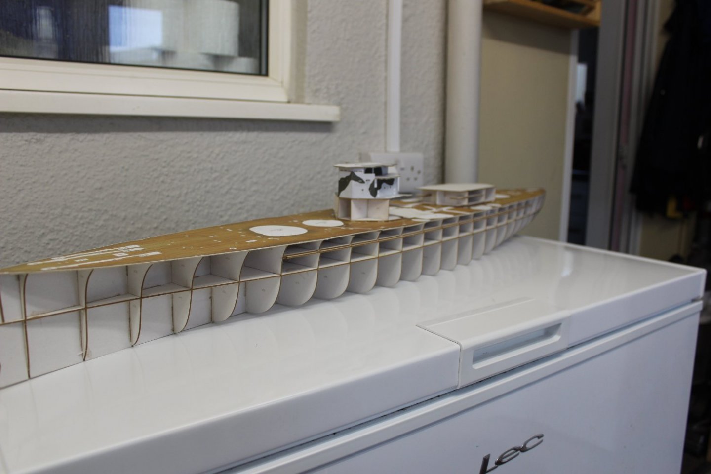
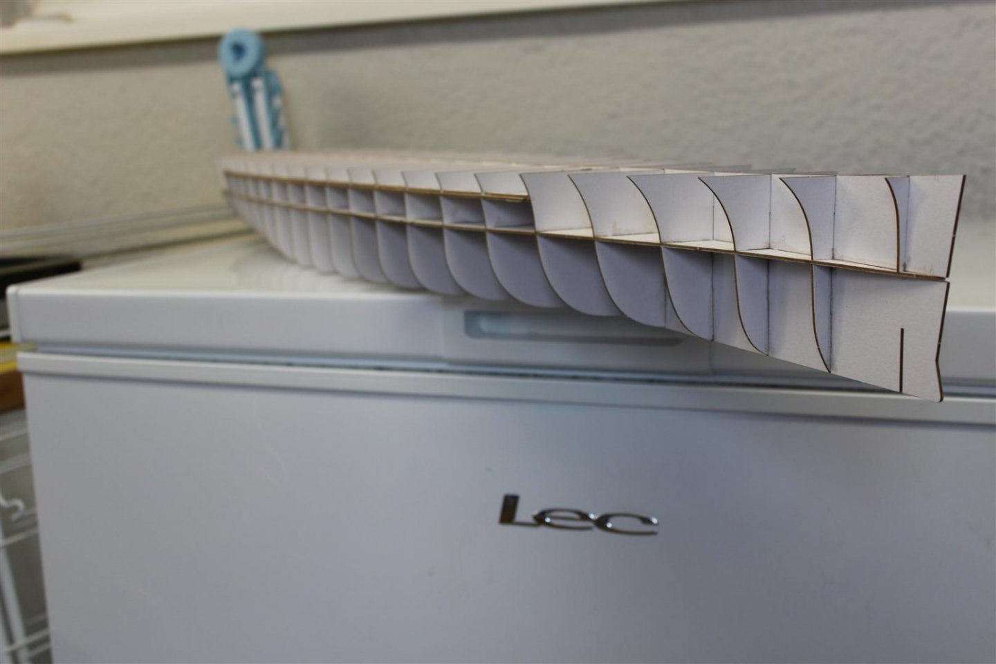
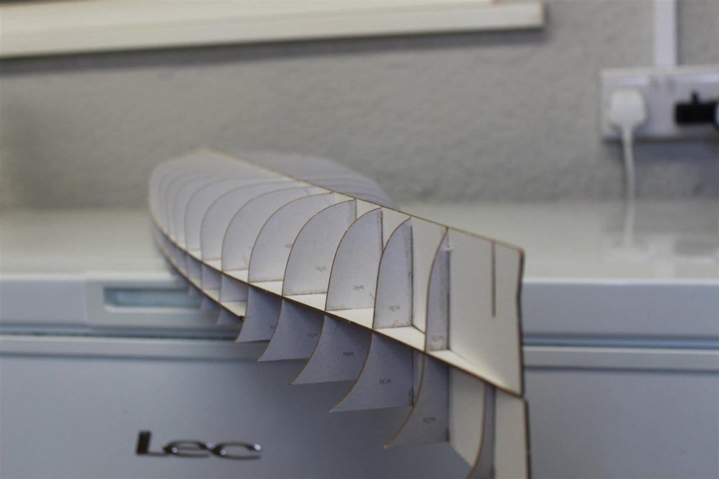
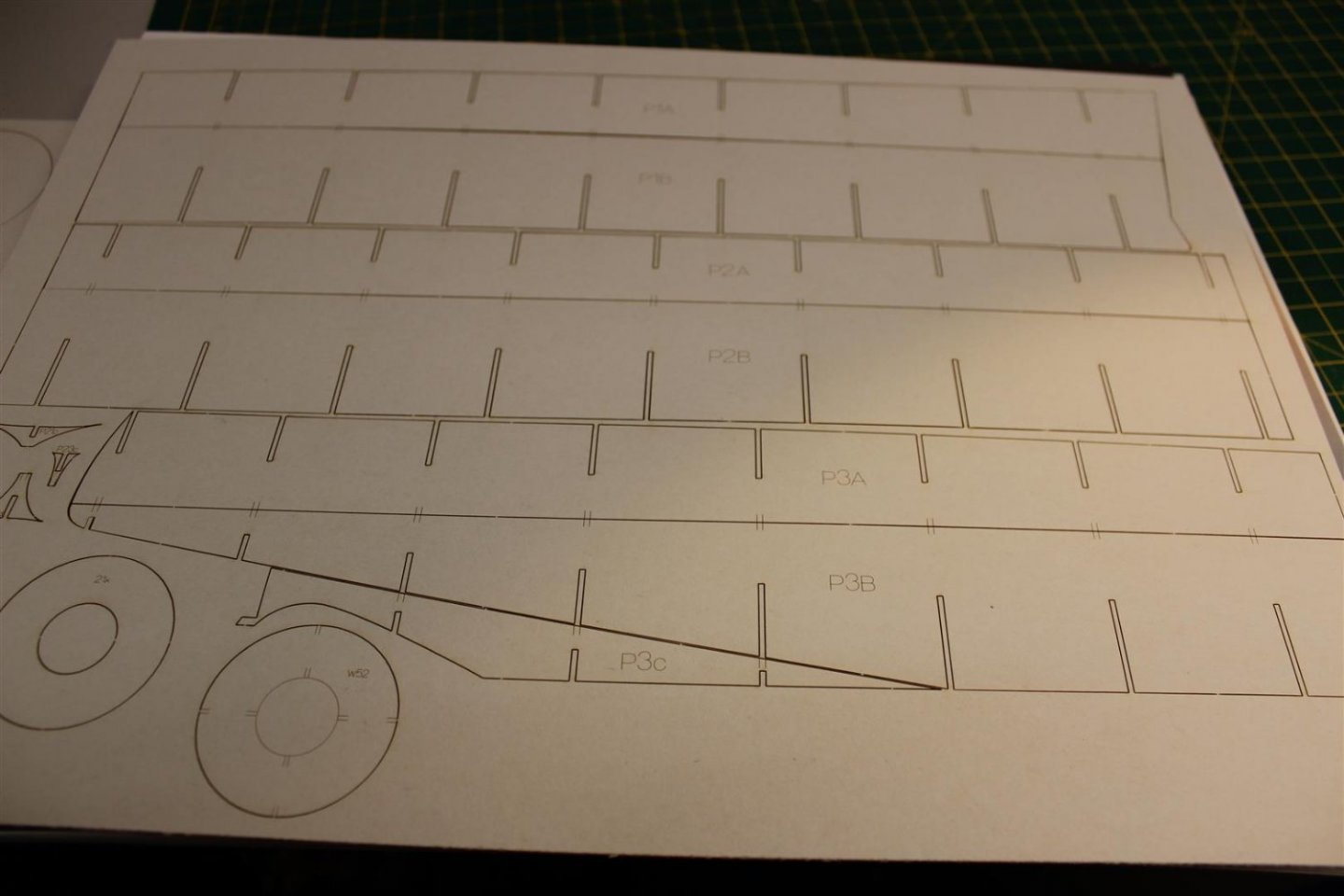
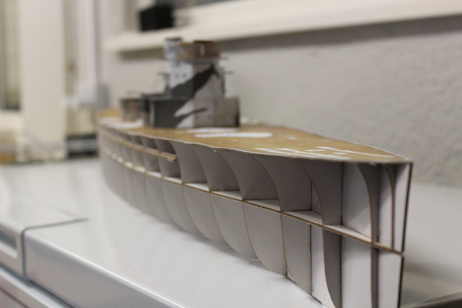
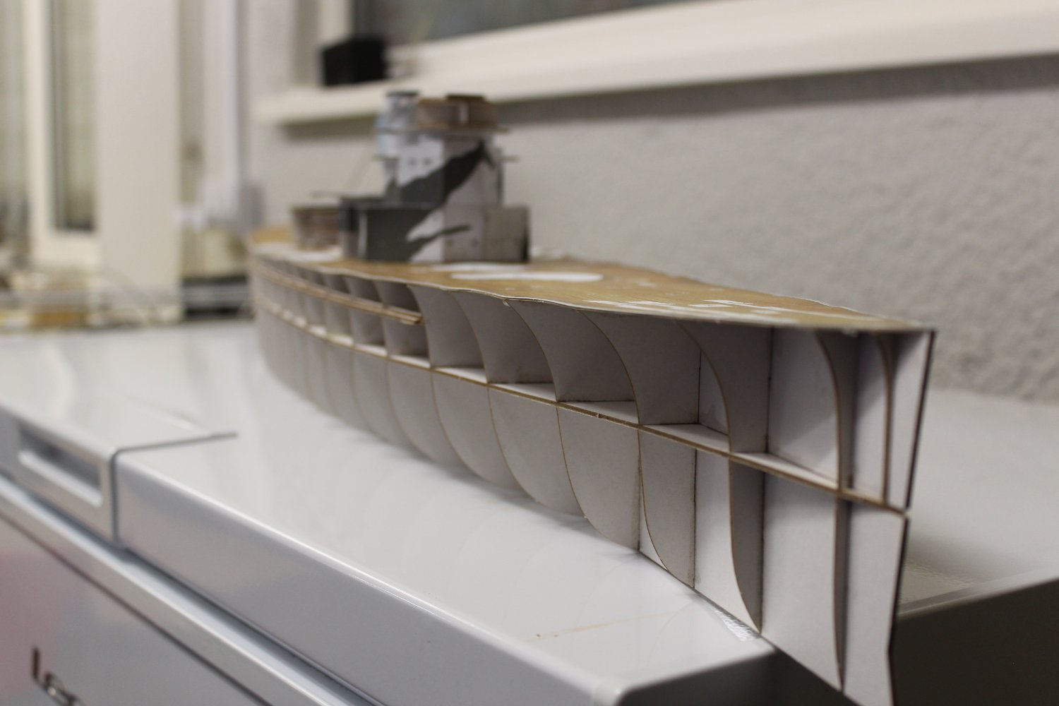
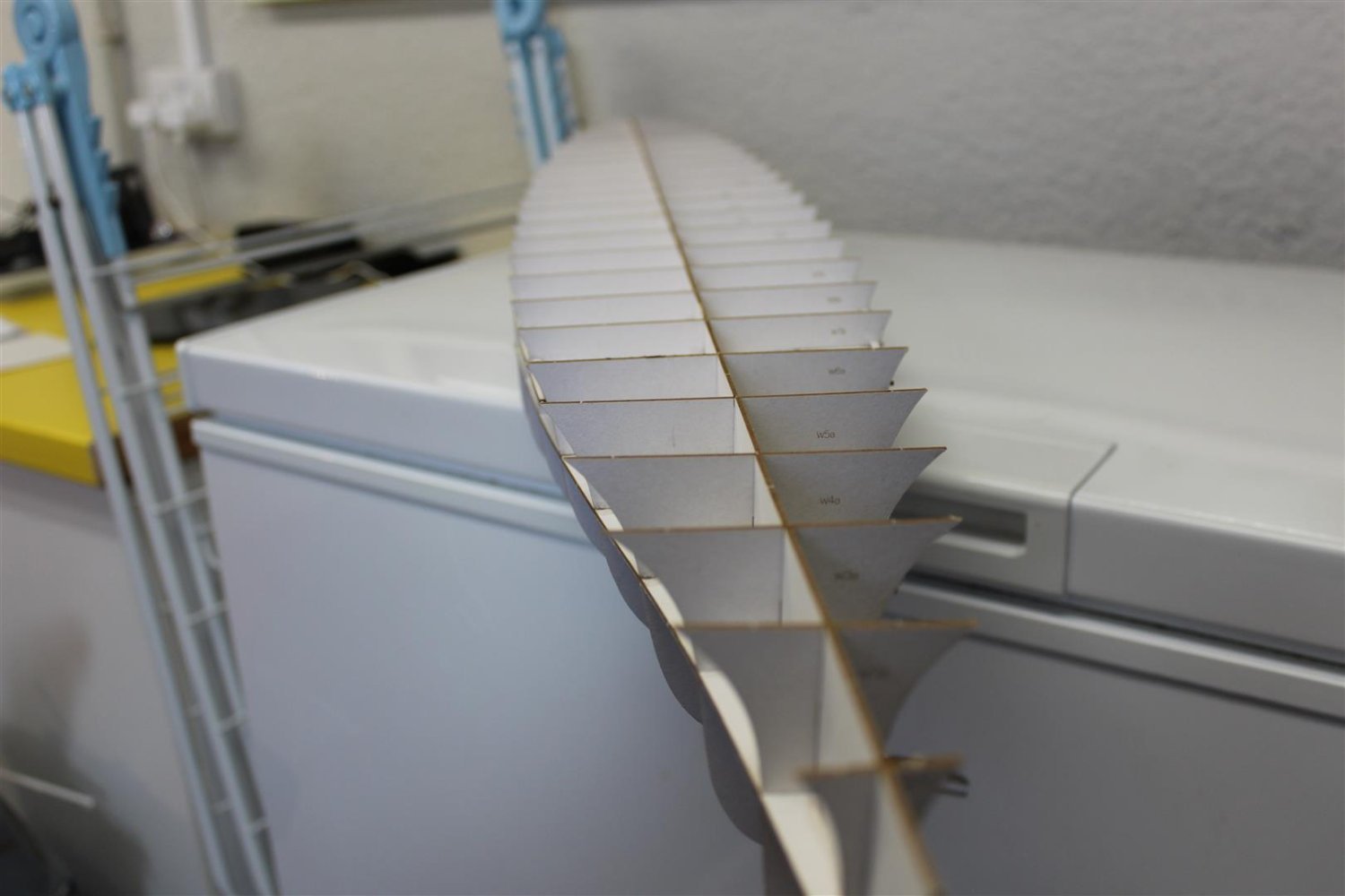
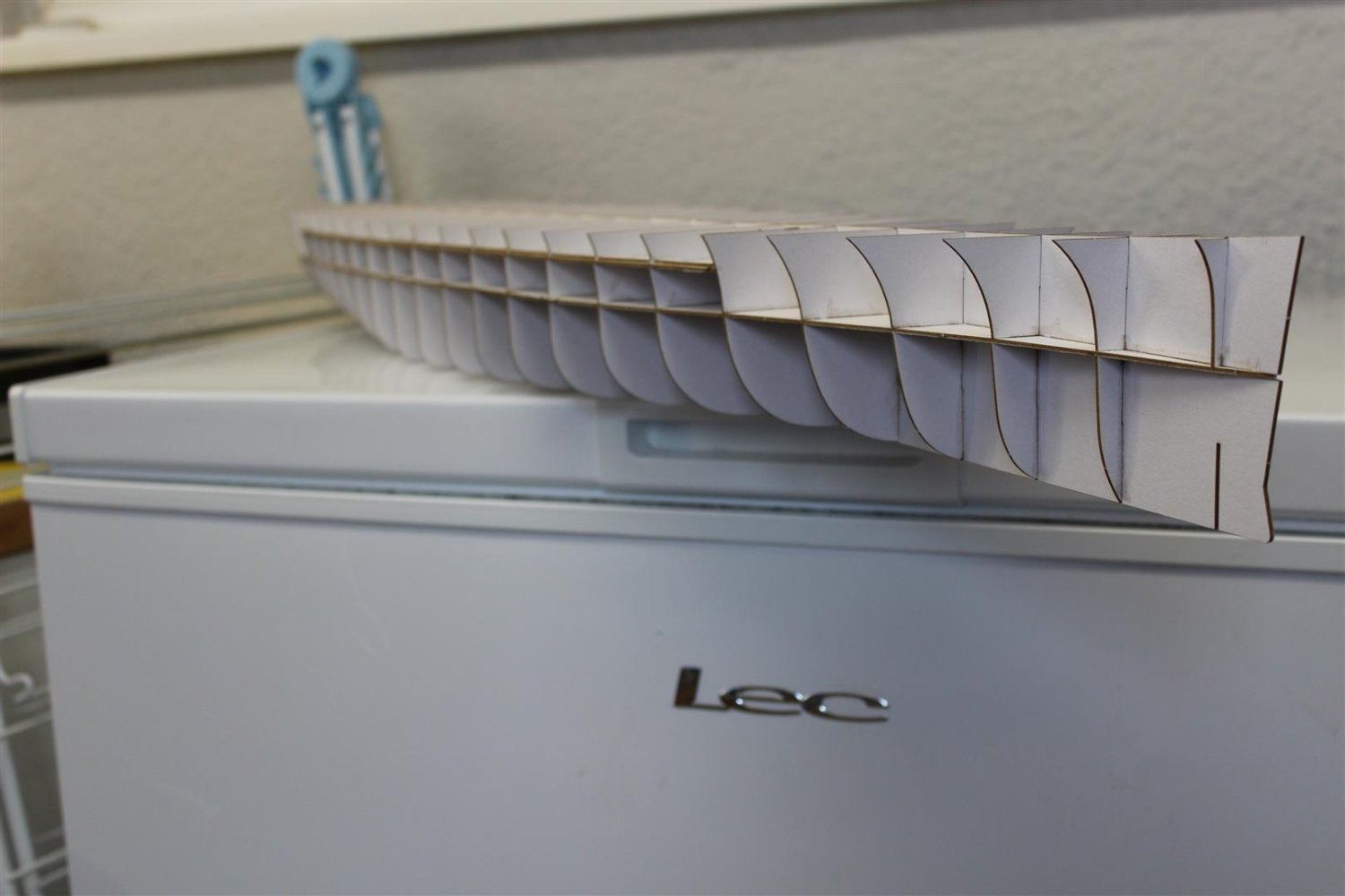
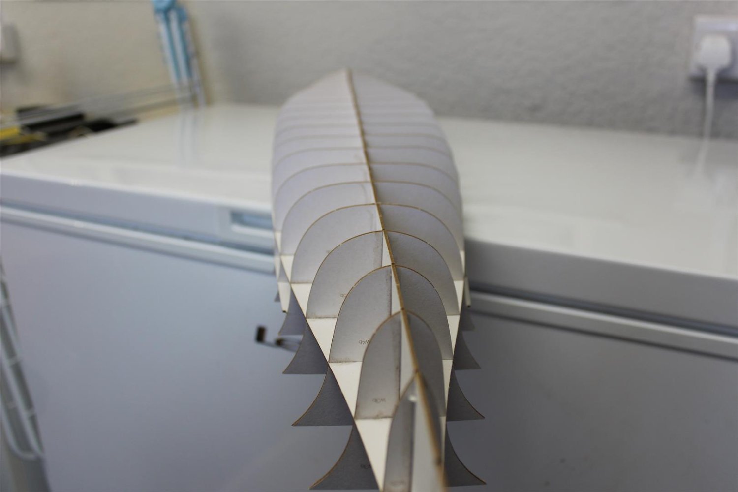
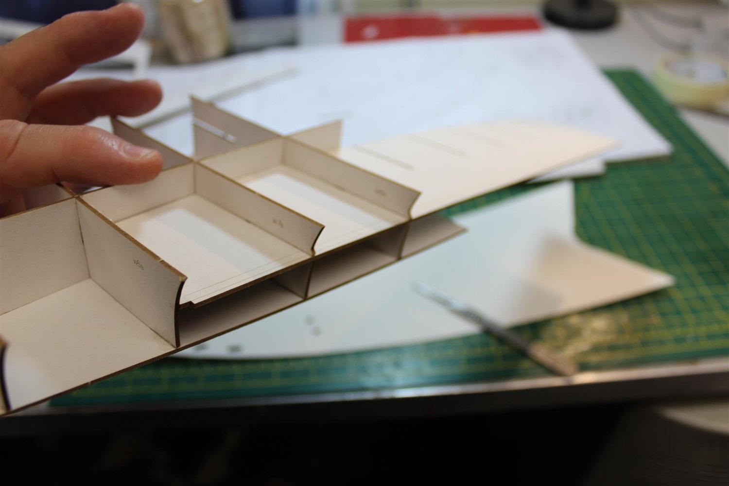
well the bottom half of the hull also went on ok, it is clearly marked where the frames go, as for the centre line, it is straighter than anything i have build before
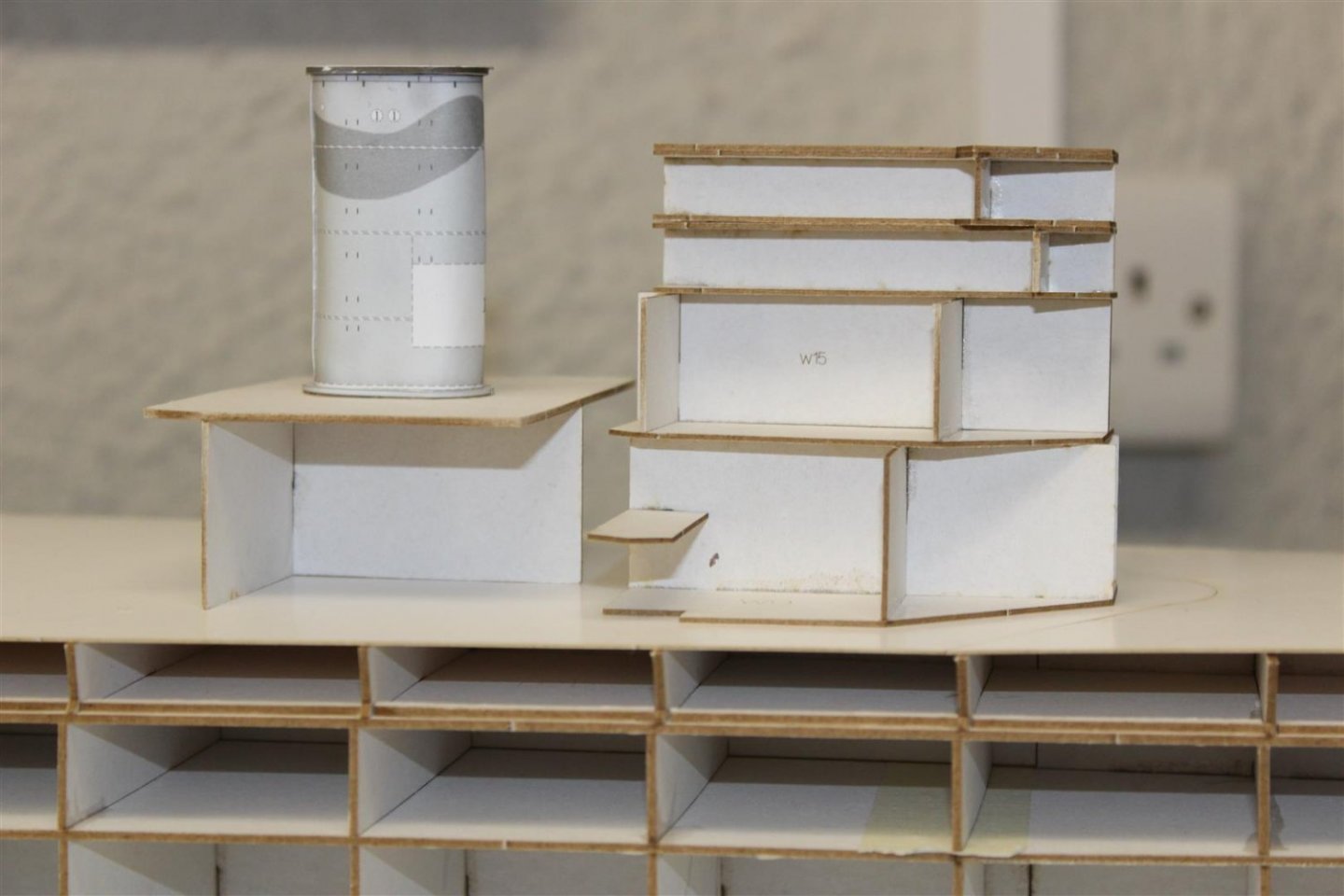
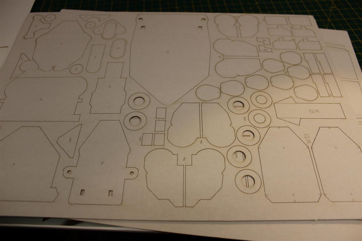
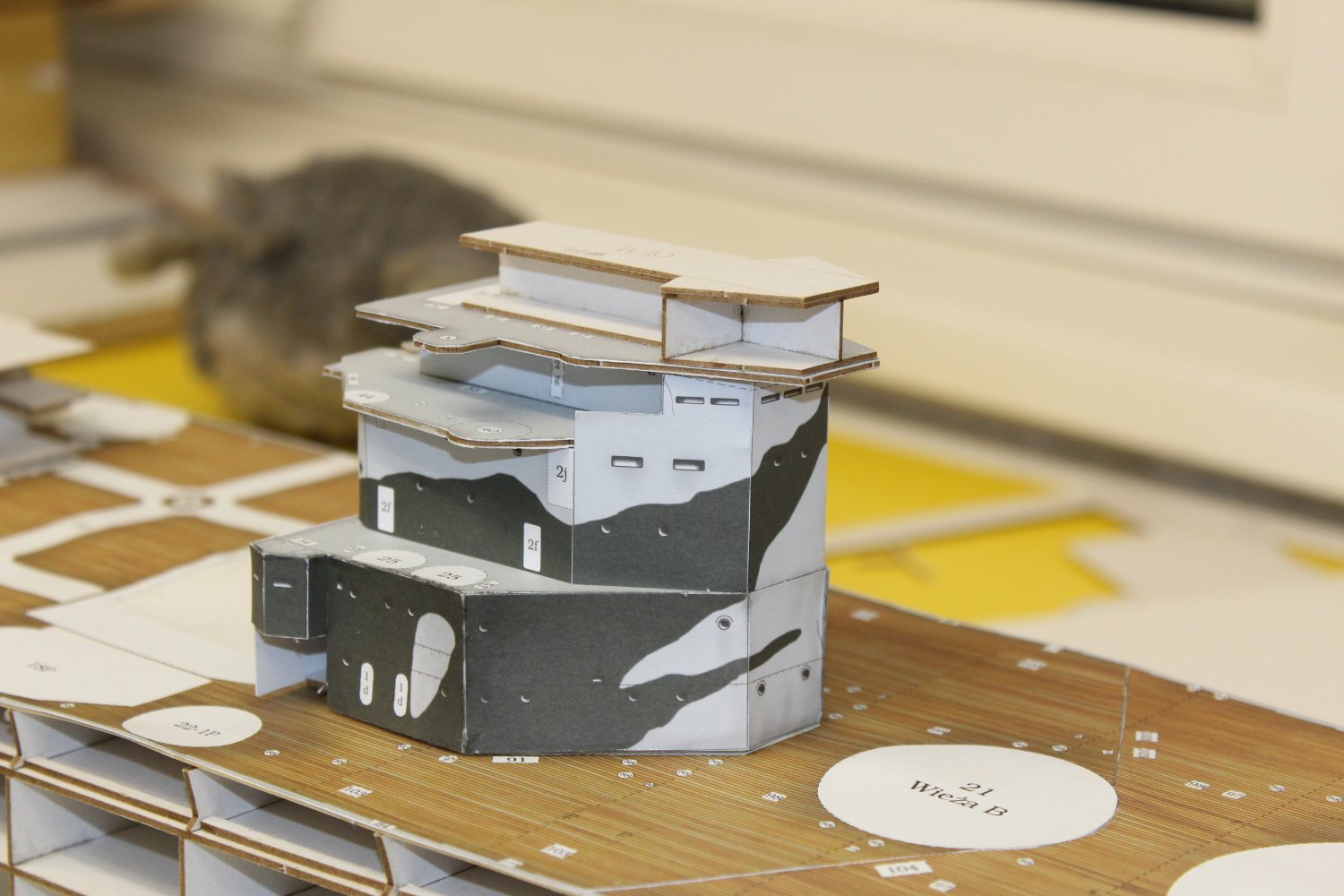
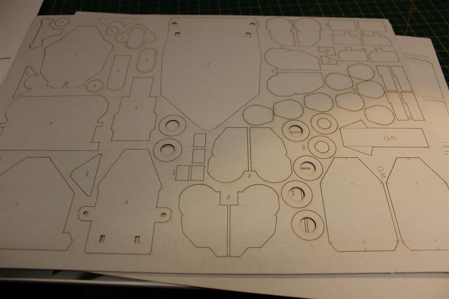
all the laser cut pieces were pushed out and filed, then i decided to use them to build up some of the superstructure,
i need to find a decent log now from somewhere and work out what to do with the upper deck, there is a card template that fits over the bulkheads and then the printed deck fits over that, i just need some guidance as to whether to fix the deck sheet to the card template , then stick the two on top or if they need to be done separately (dont suppose it matter)
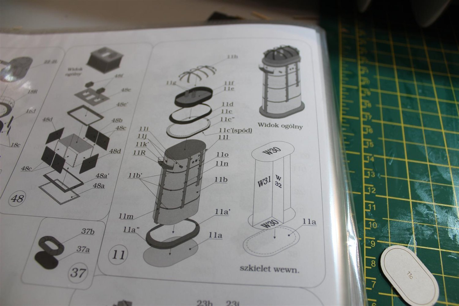
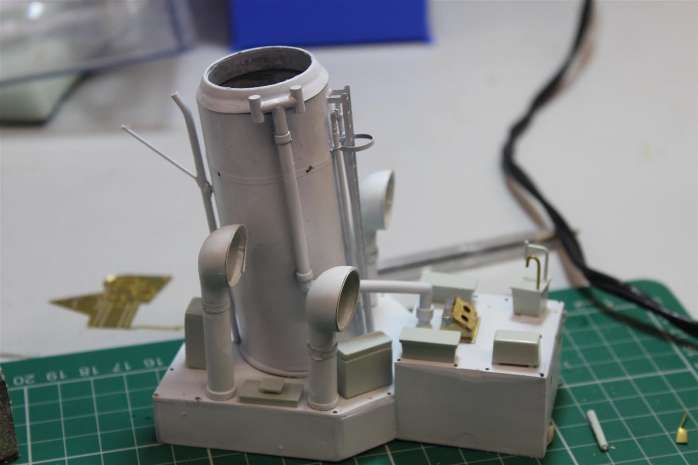
i even had a go at the funnel, its quite hard on the eyes
fun factor 10/10


laser cut superstructure
funnel instructions


-
4 hours ago, Old Collingwood said:
Based on your ability and the inherent difficulties with card kits - this could be one of your very best builds - take it steady Kevin.
OC.
thank you OC
- mtaylor, Old Collingwood and Canute
-
3
-
-
5 hours ago, ccoyle said:
Here, Kevin -- I have created a Polish-English dictionary for you based on my "extensive working knowledge" of the language:
- okrety: ship
- klej: glue
- drut: wire
Okay, that's all I know. For the rest, you're on your own. 😜
Brilliant, thats made my day thank you
-
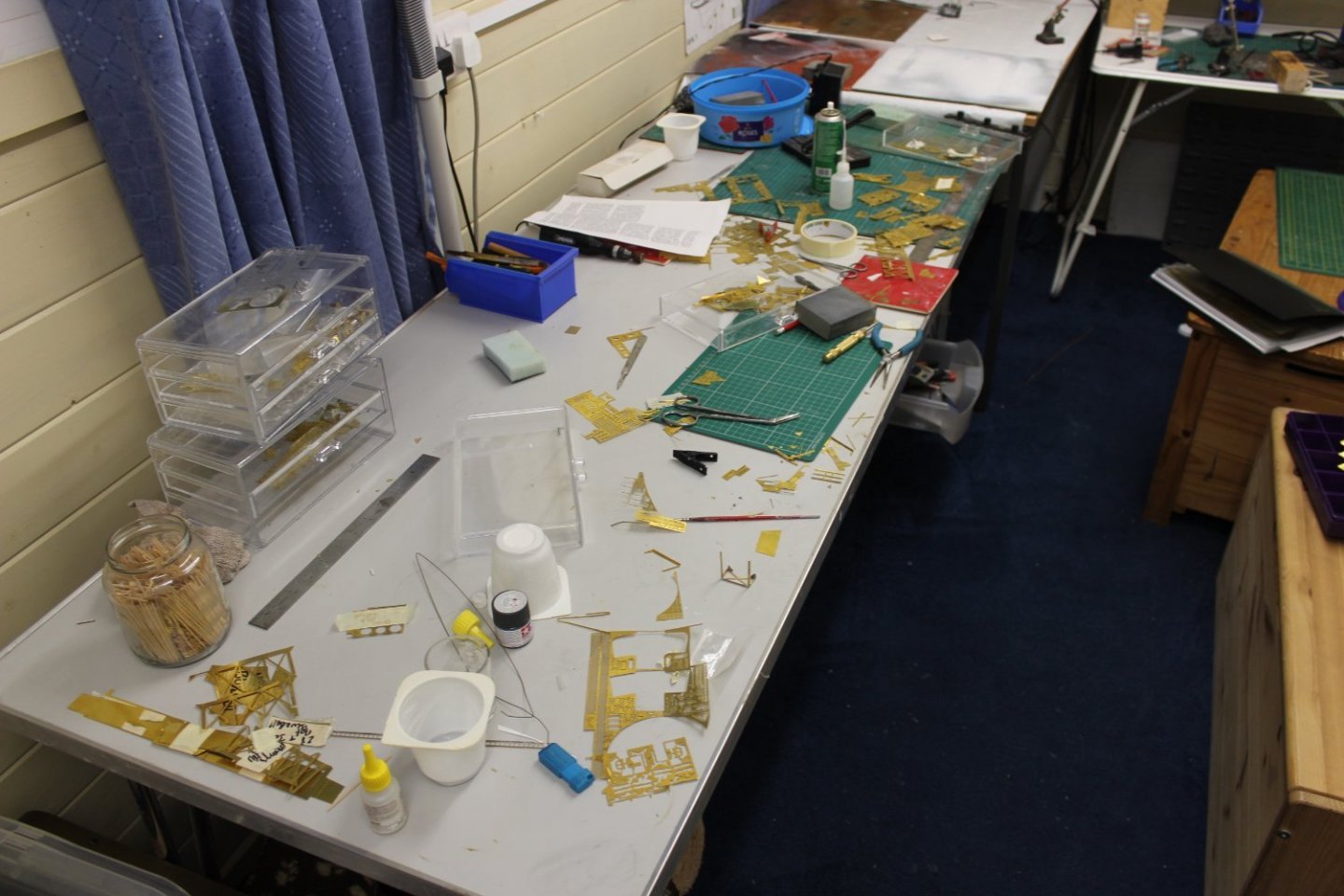
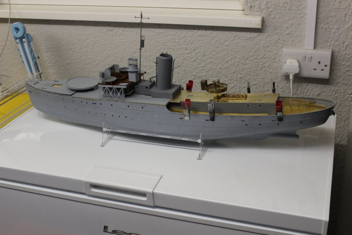
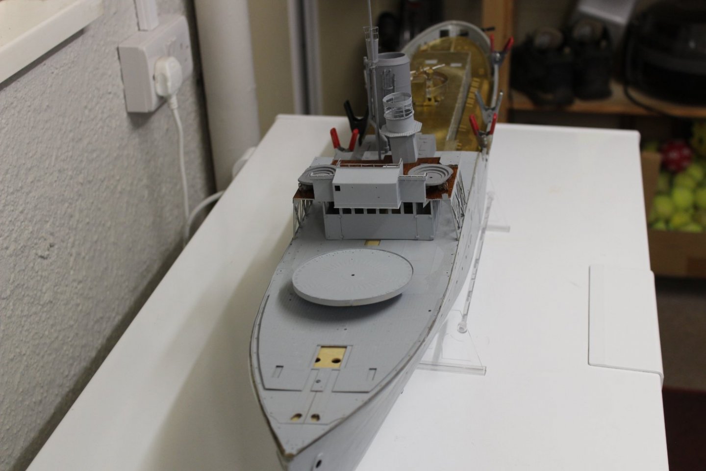
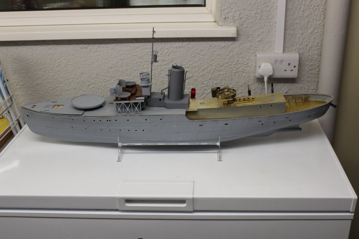
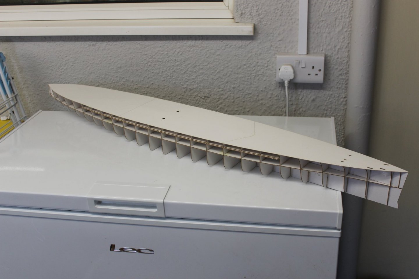
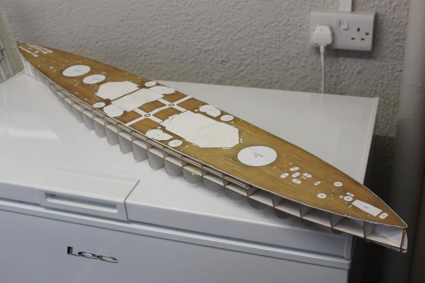
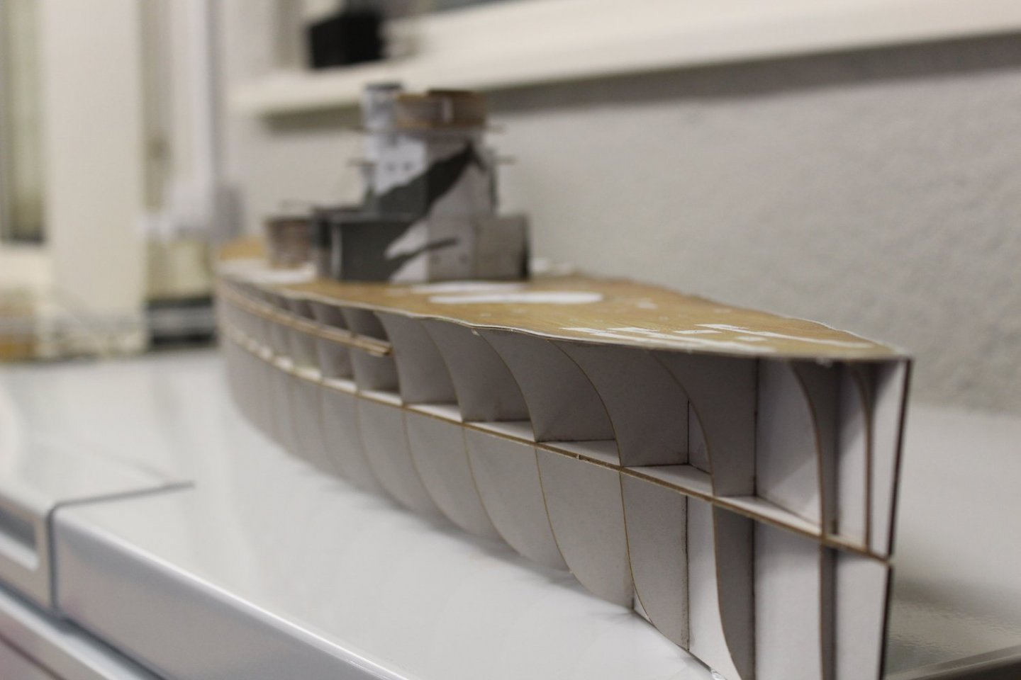
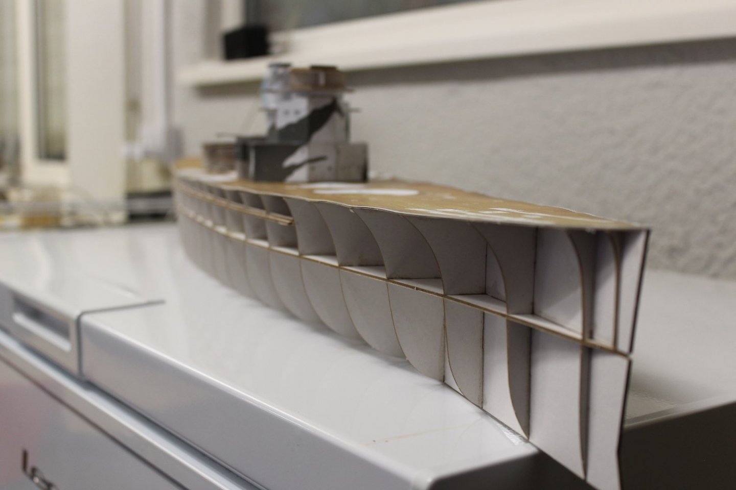
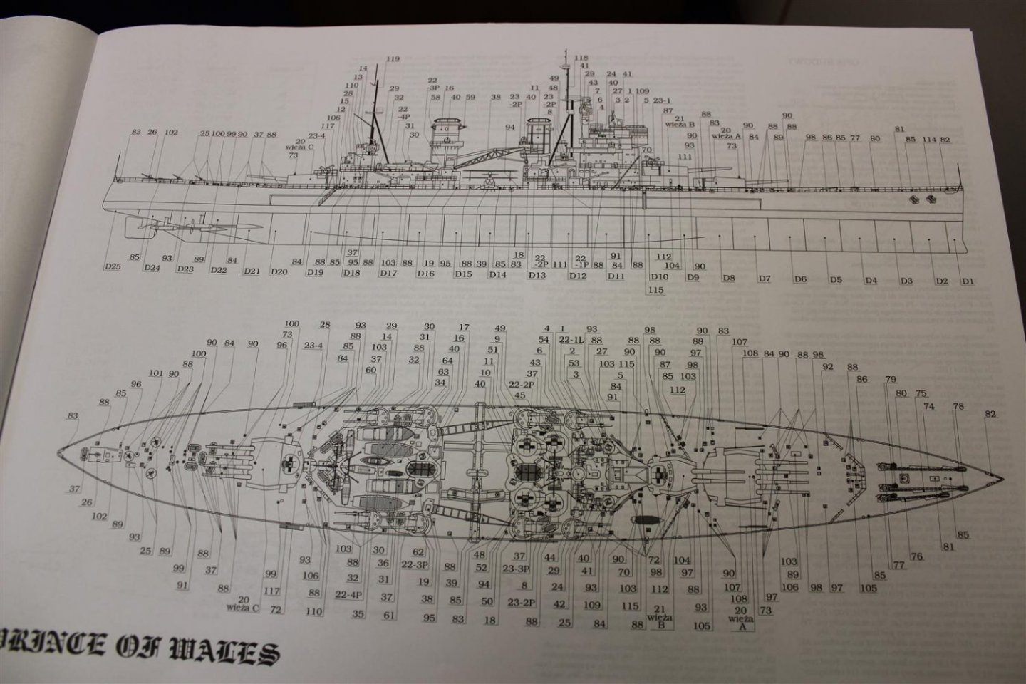
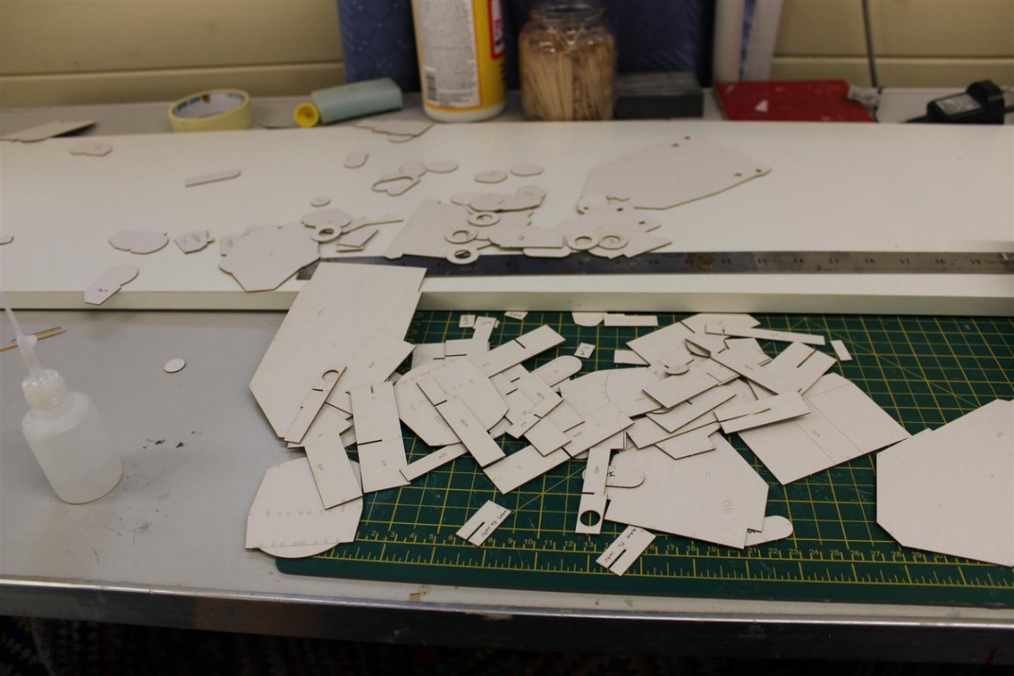
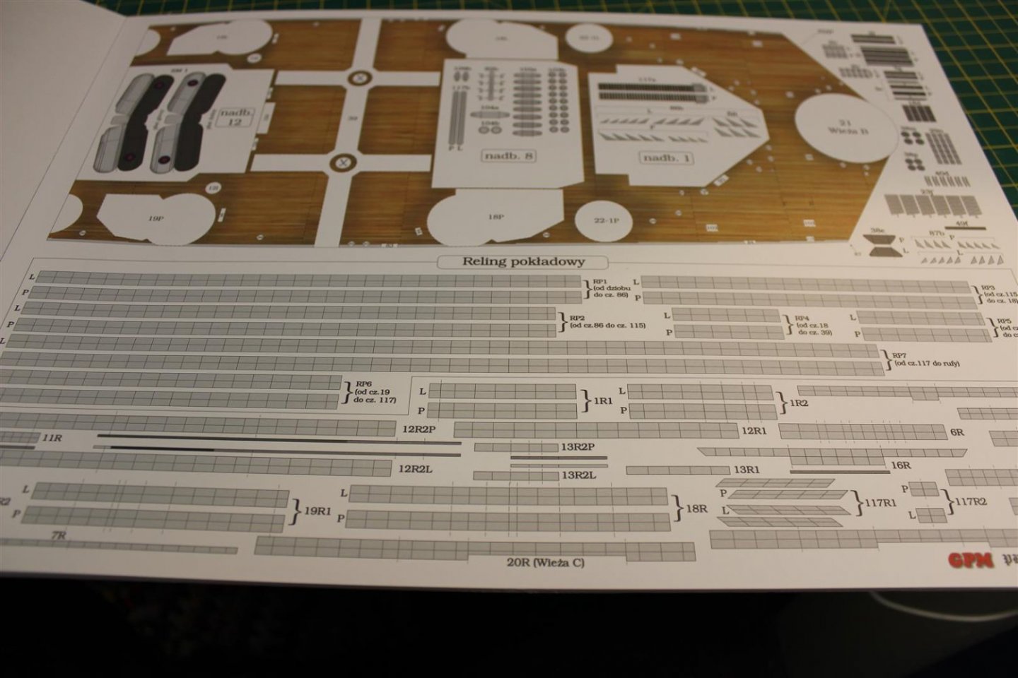
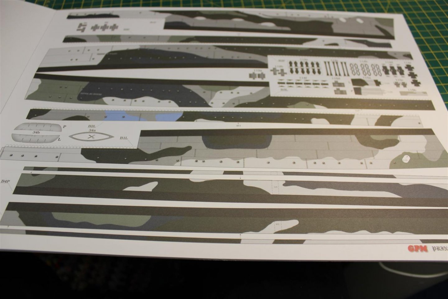
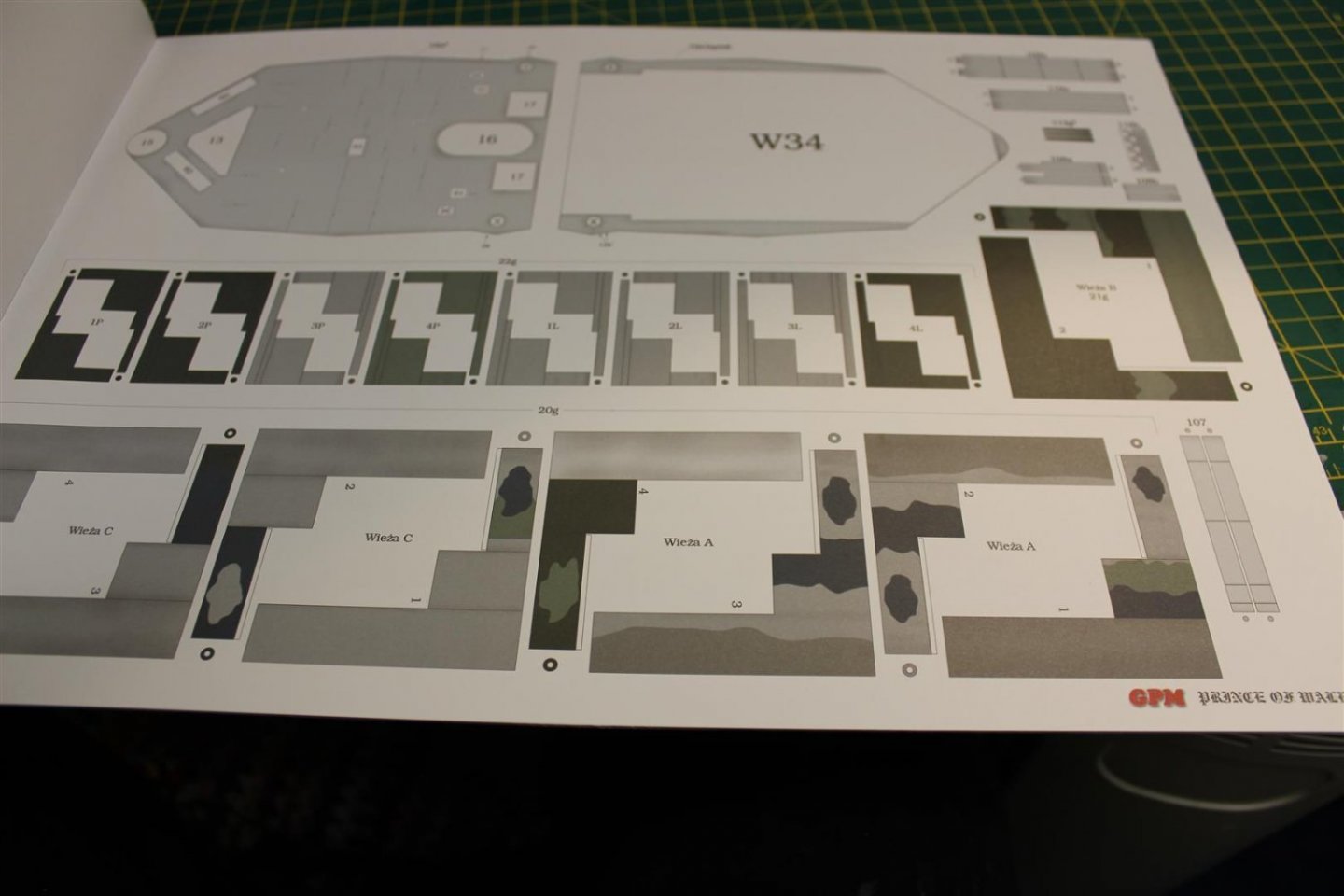
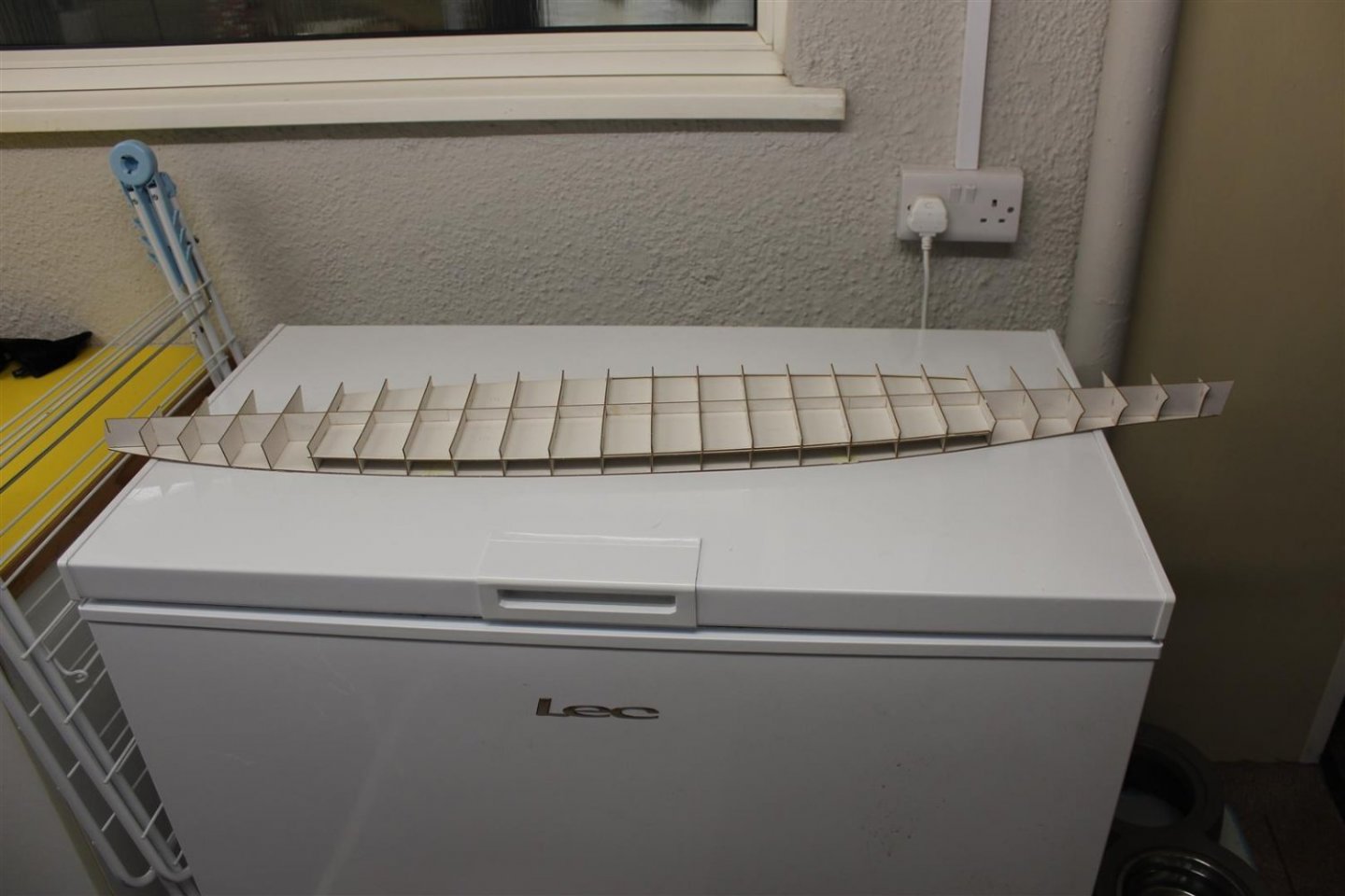
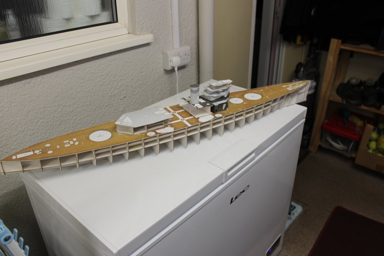
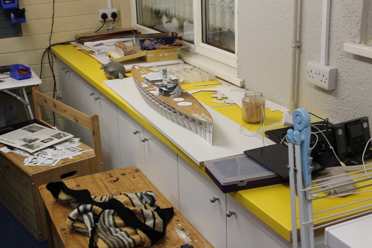
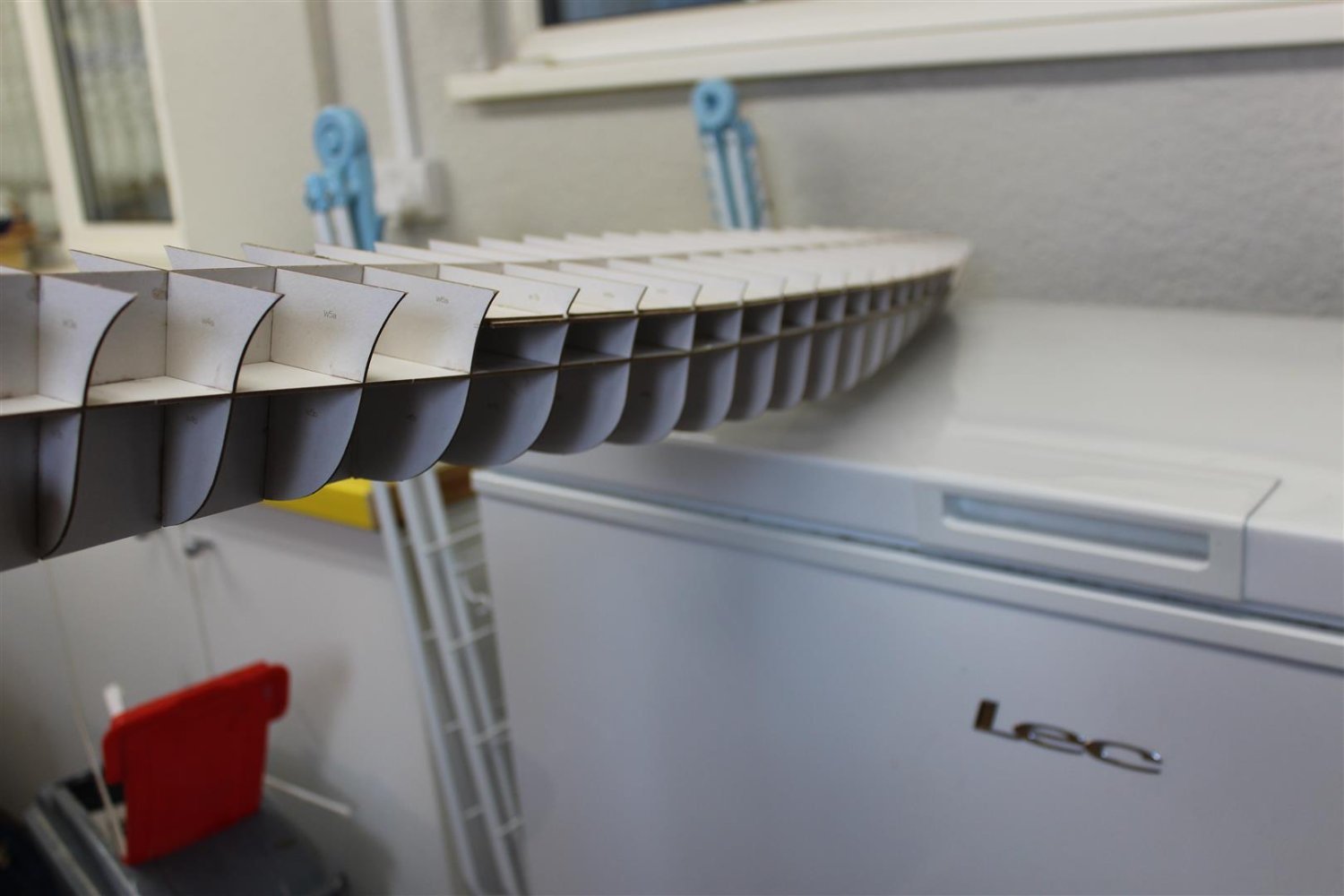
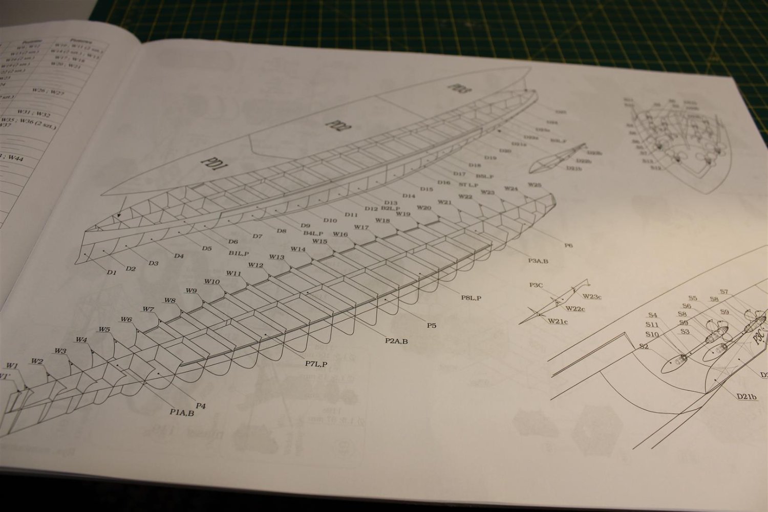
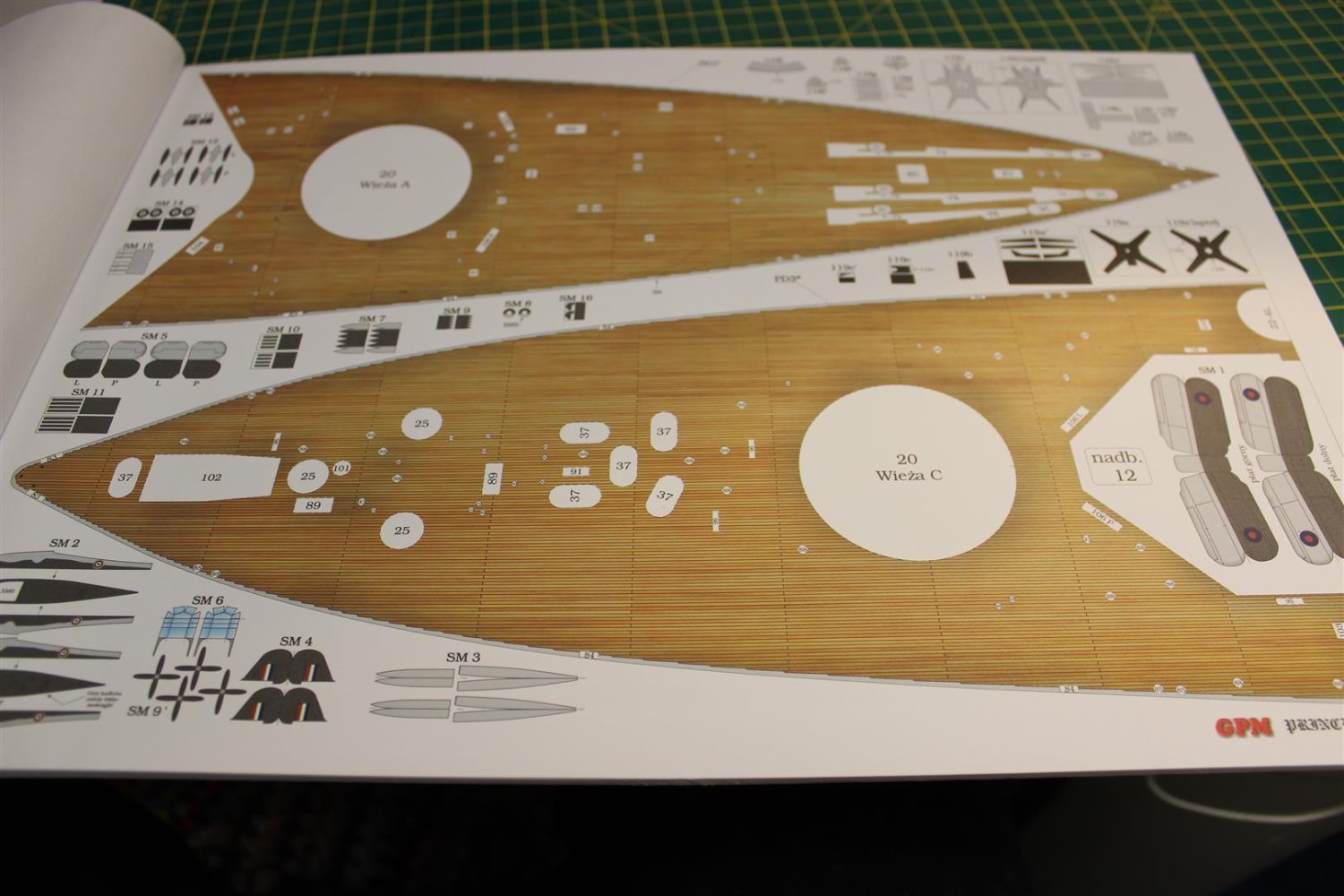
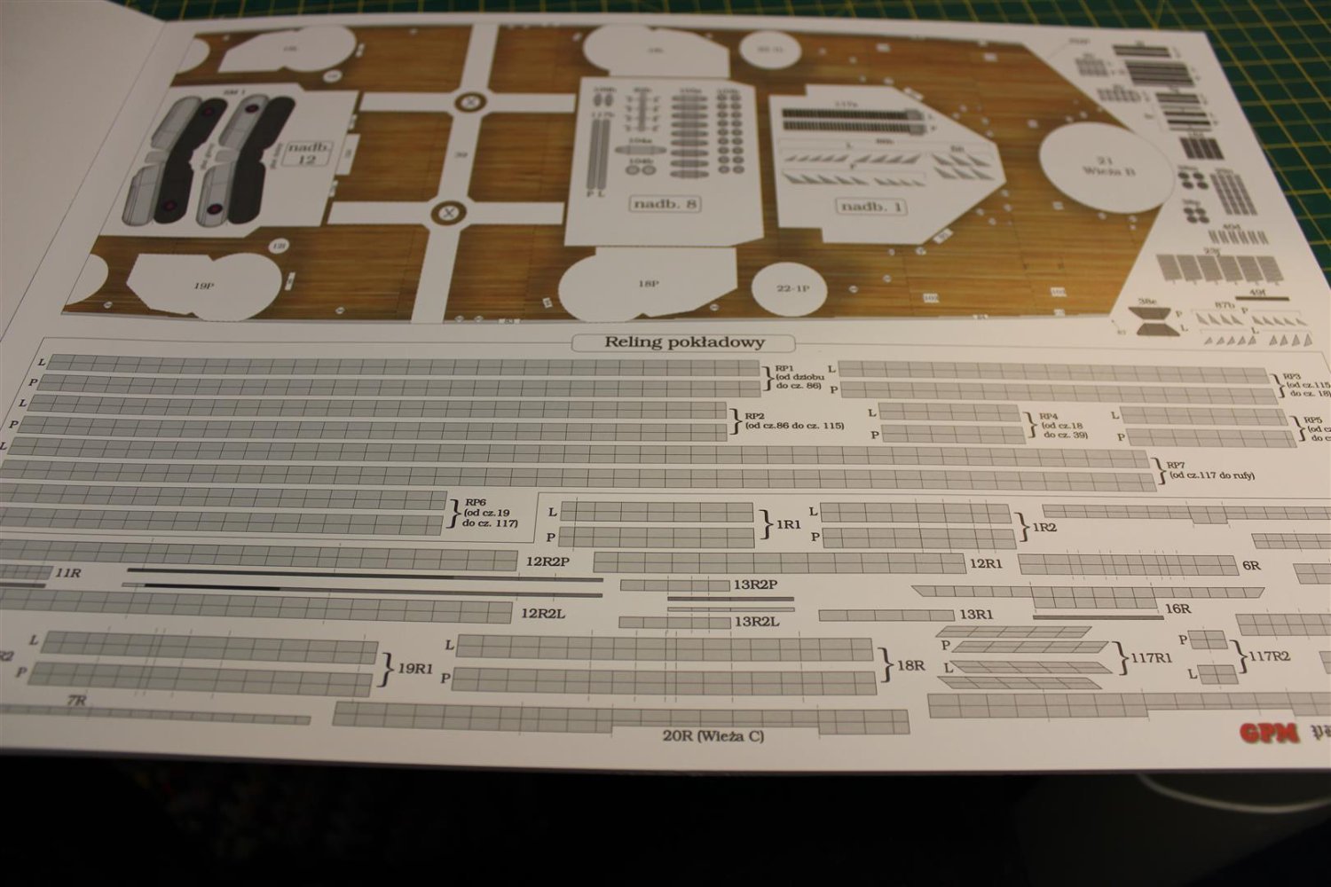
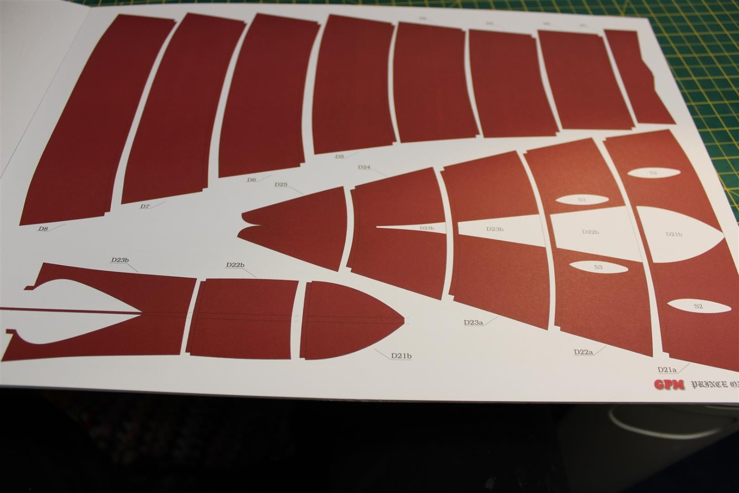
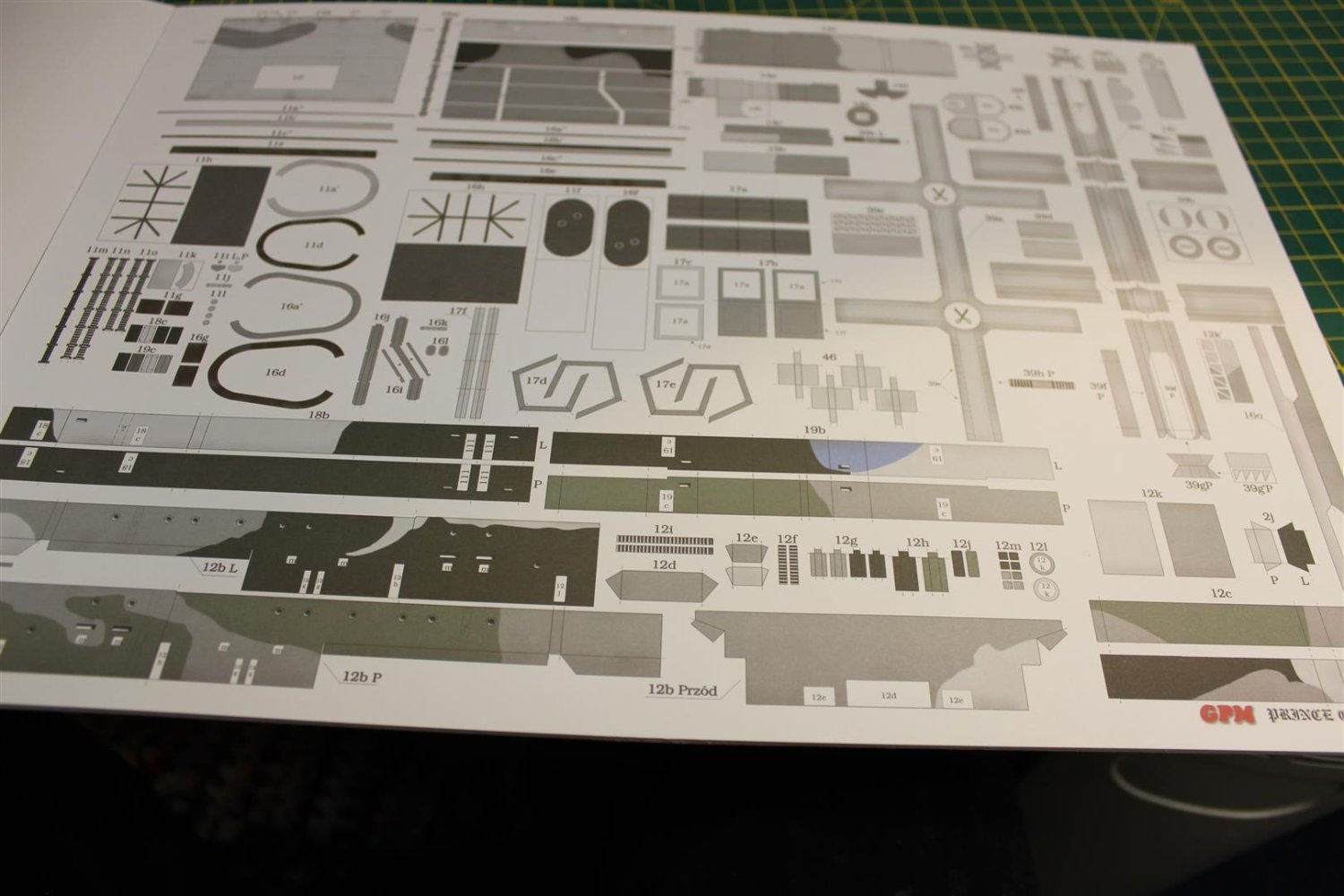
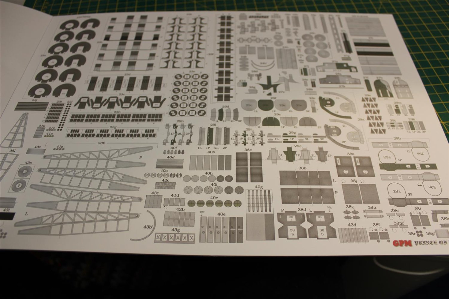
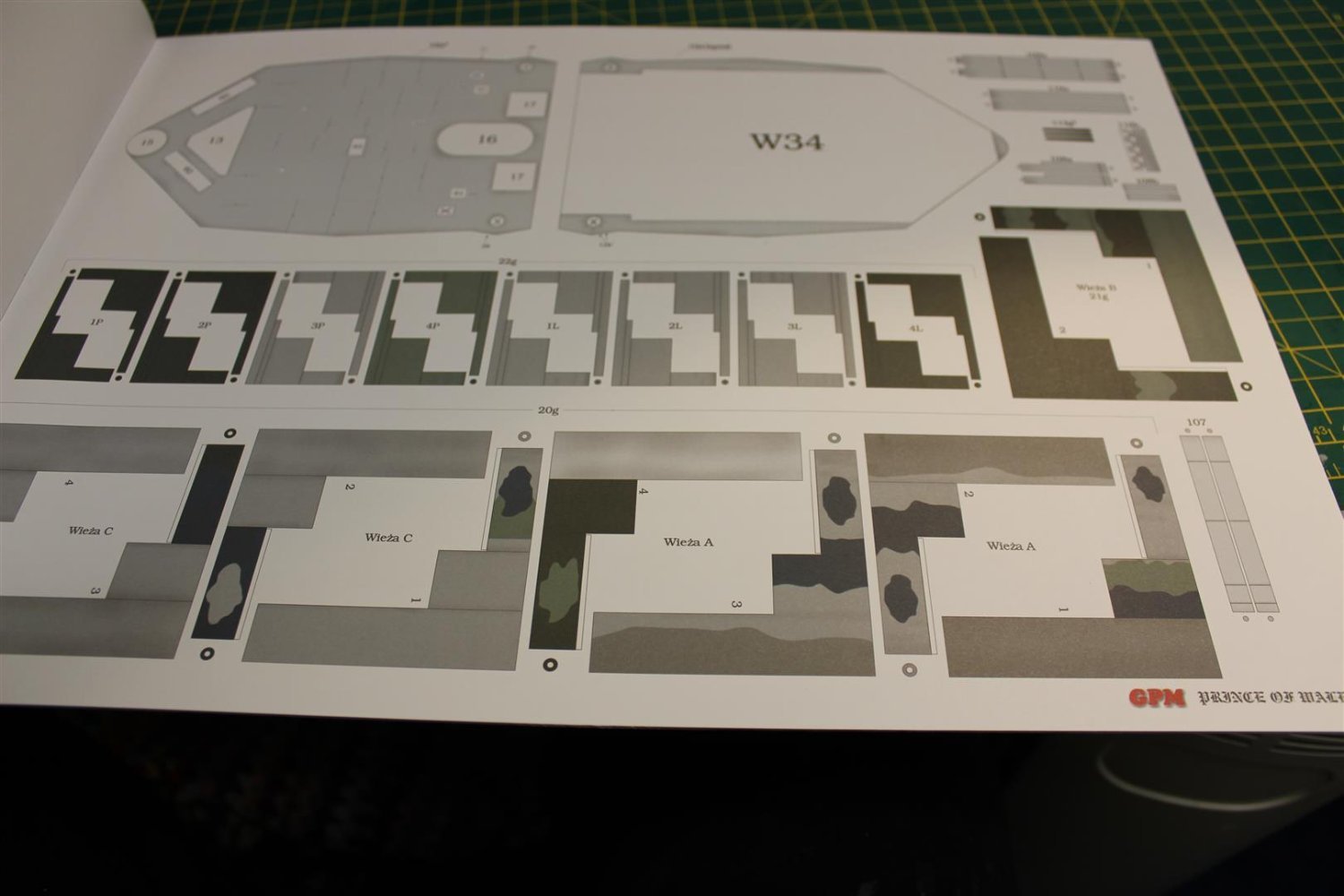
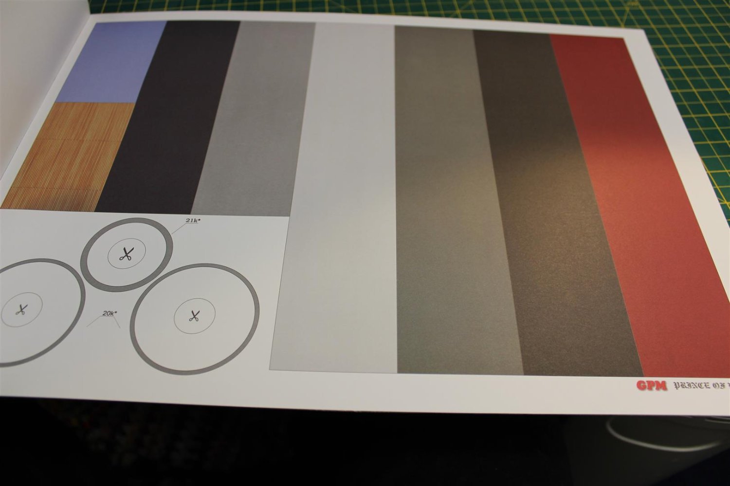
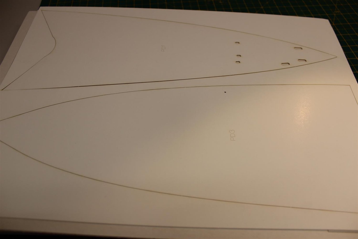
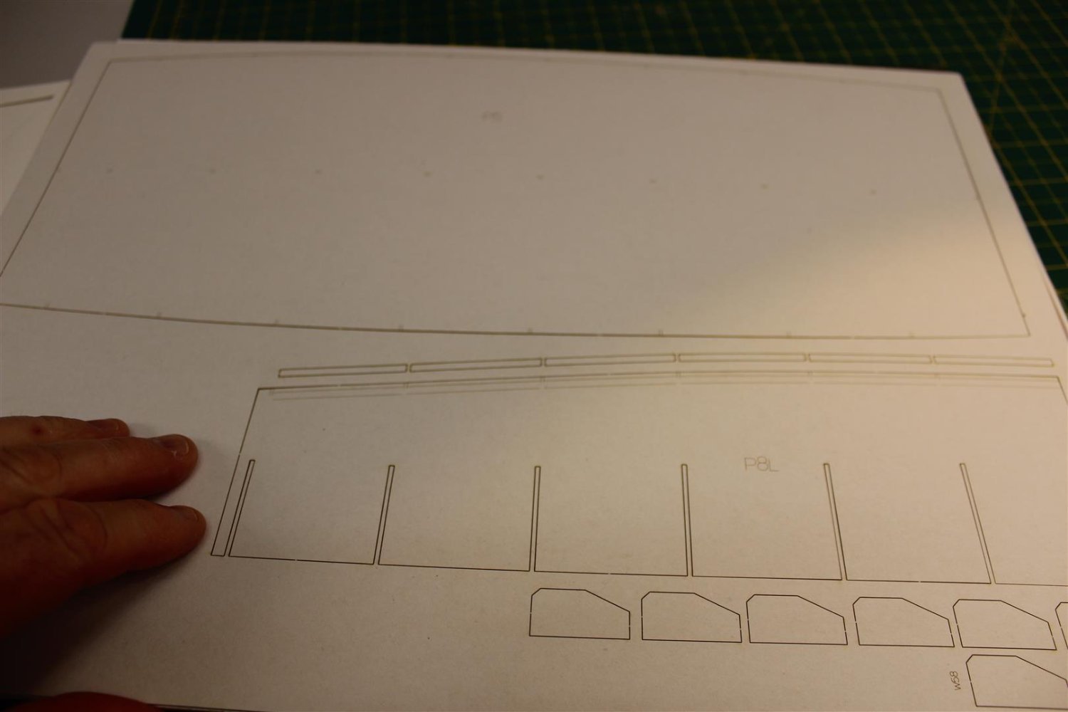
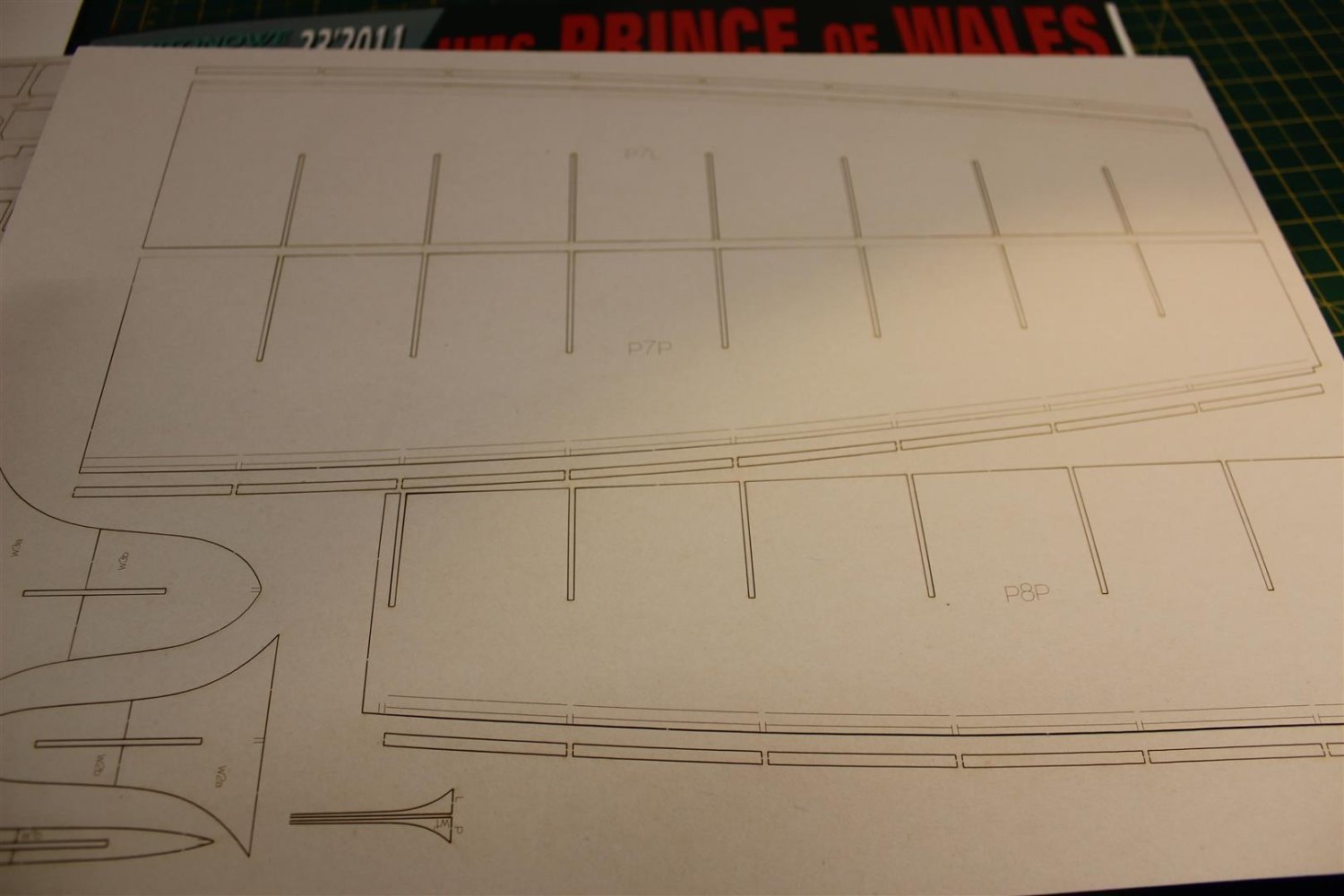
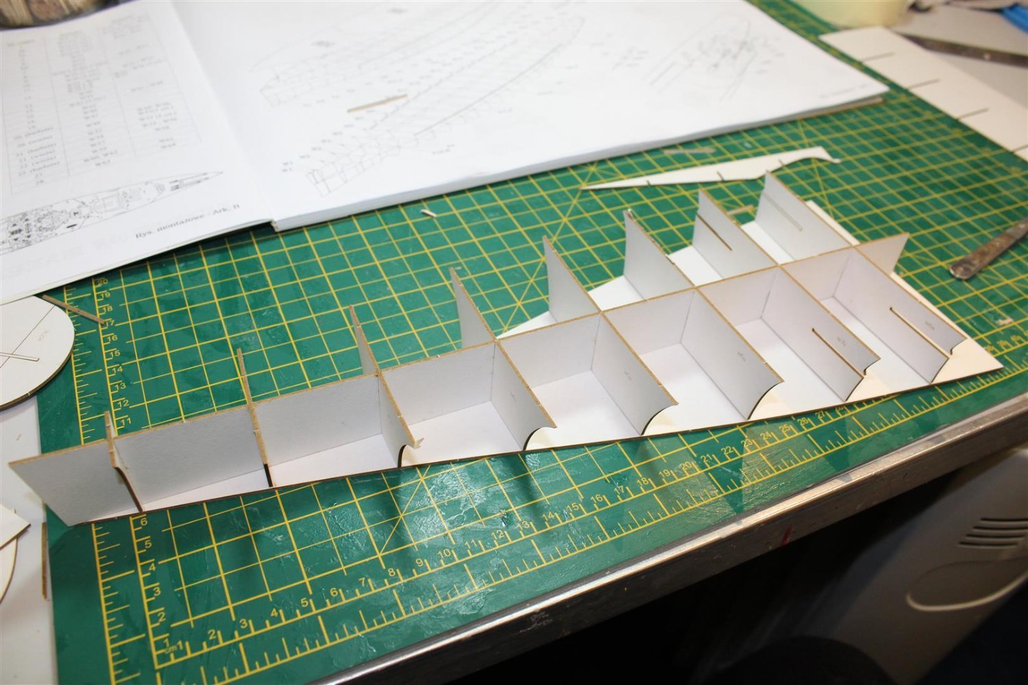
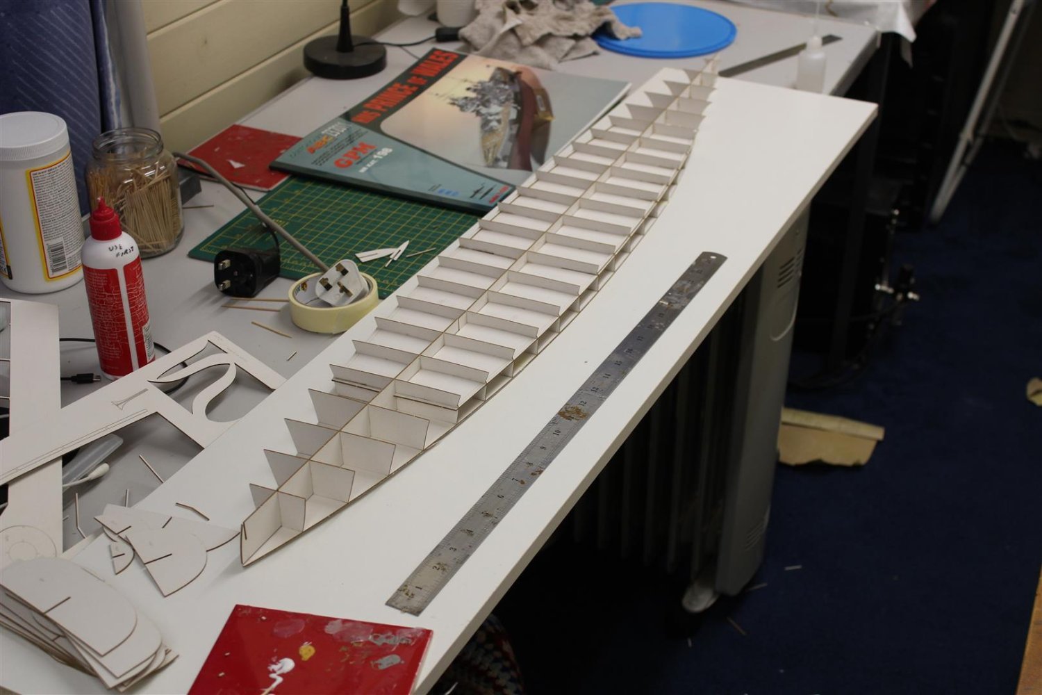
this is a 1/200 card/paper kit from GPM, it comes with the hull and superstructure in laser cut formers, which are marked very well to place the bulkheads
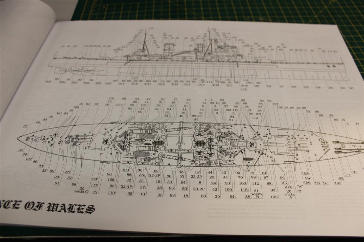
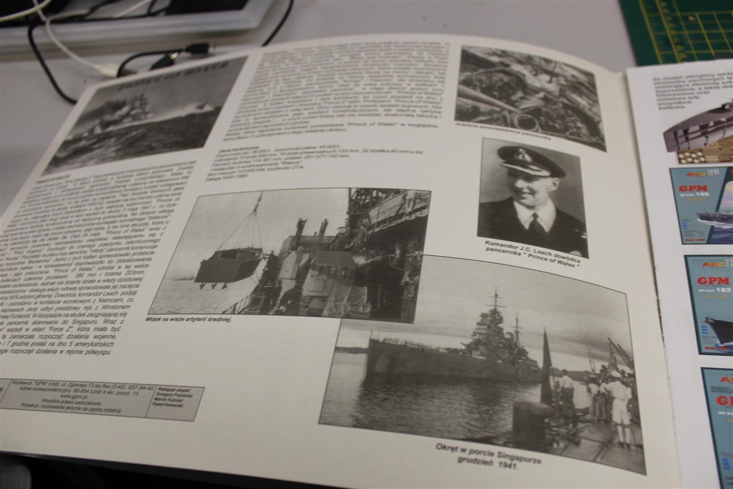
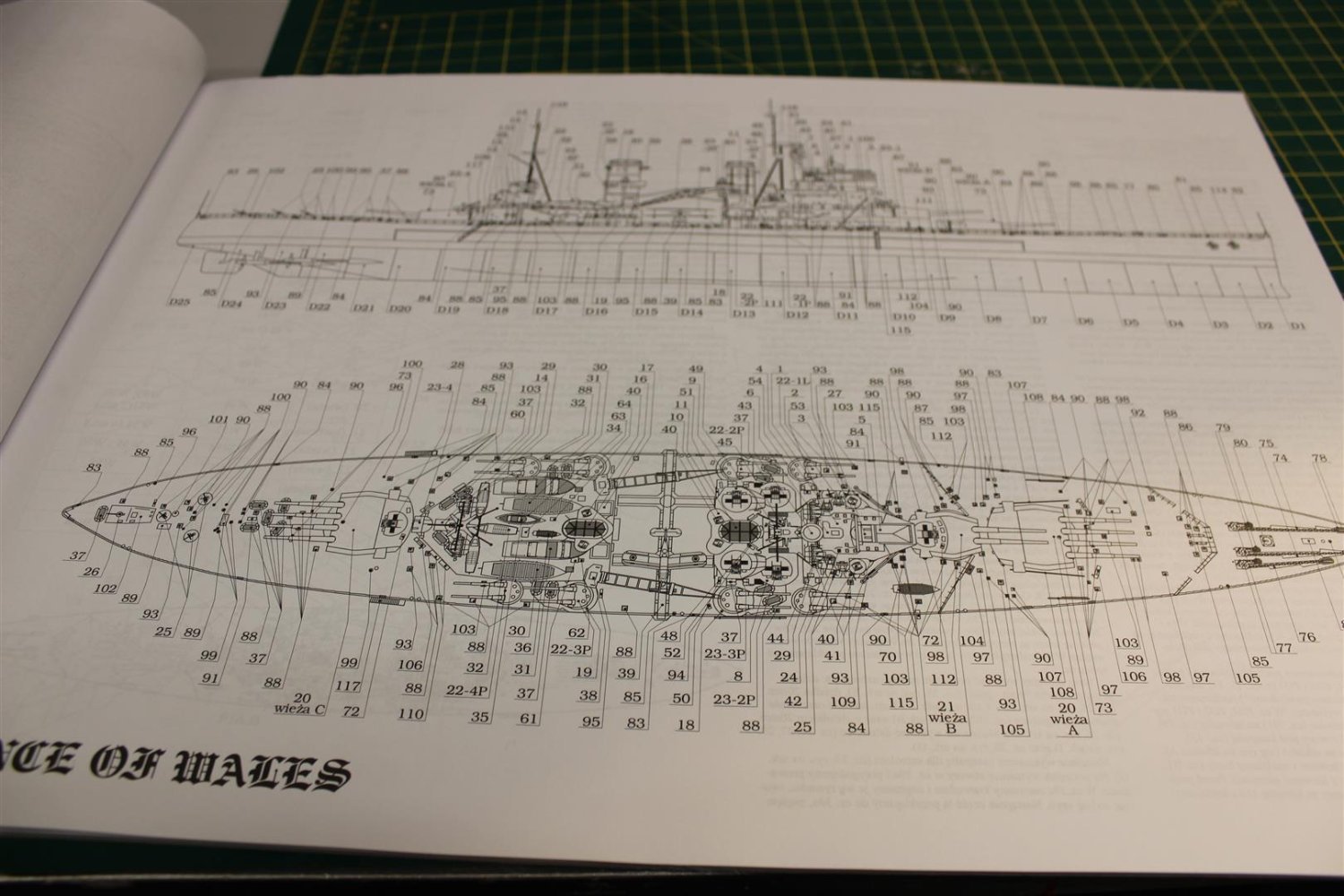
the large book contains lots of instructions (all in Polish) (which is my 2nd language NOT) and pages of identifications of the 2nd 1/2 of the book which is the actual kit
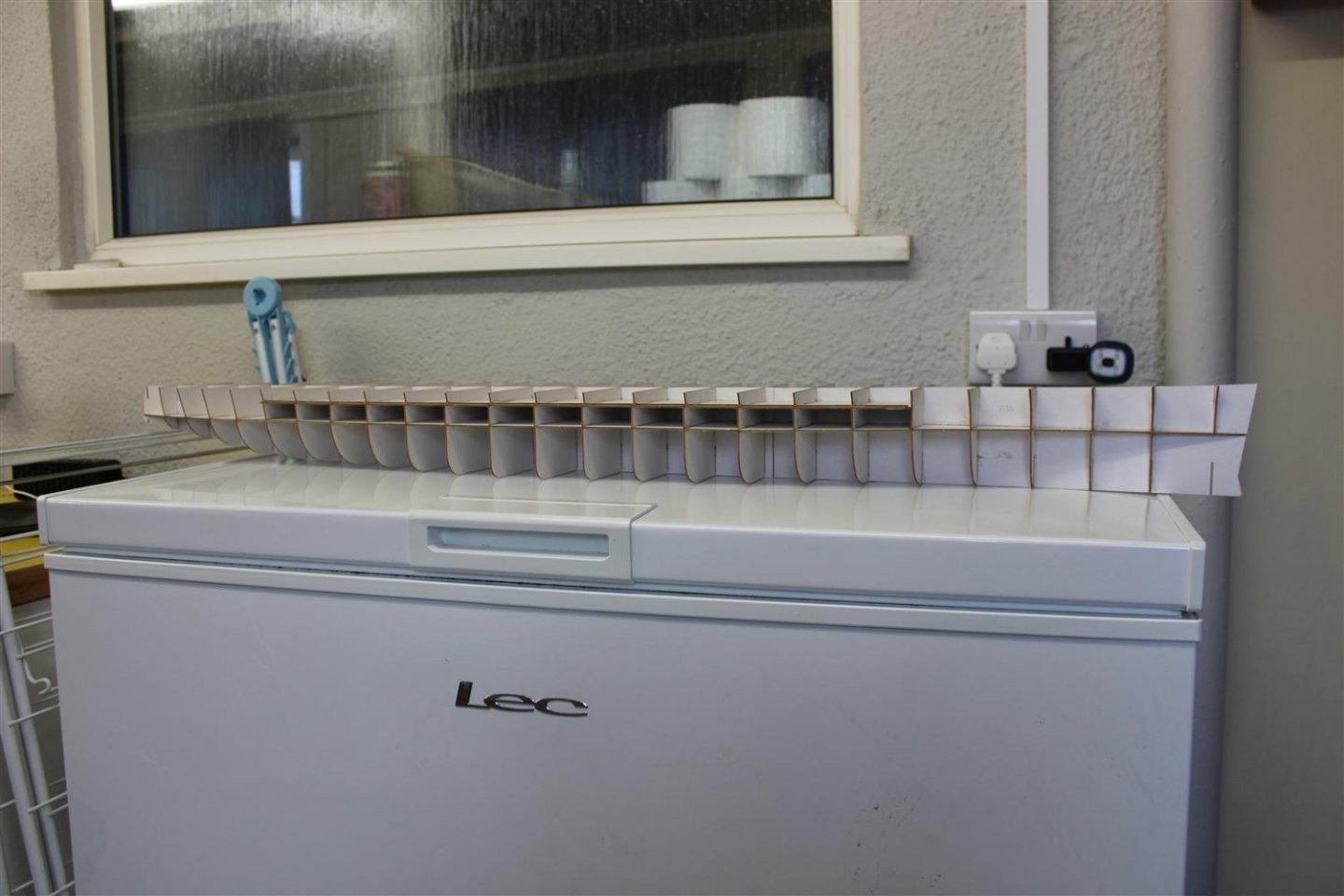
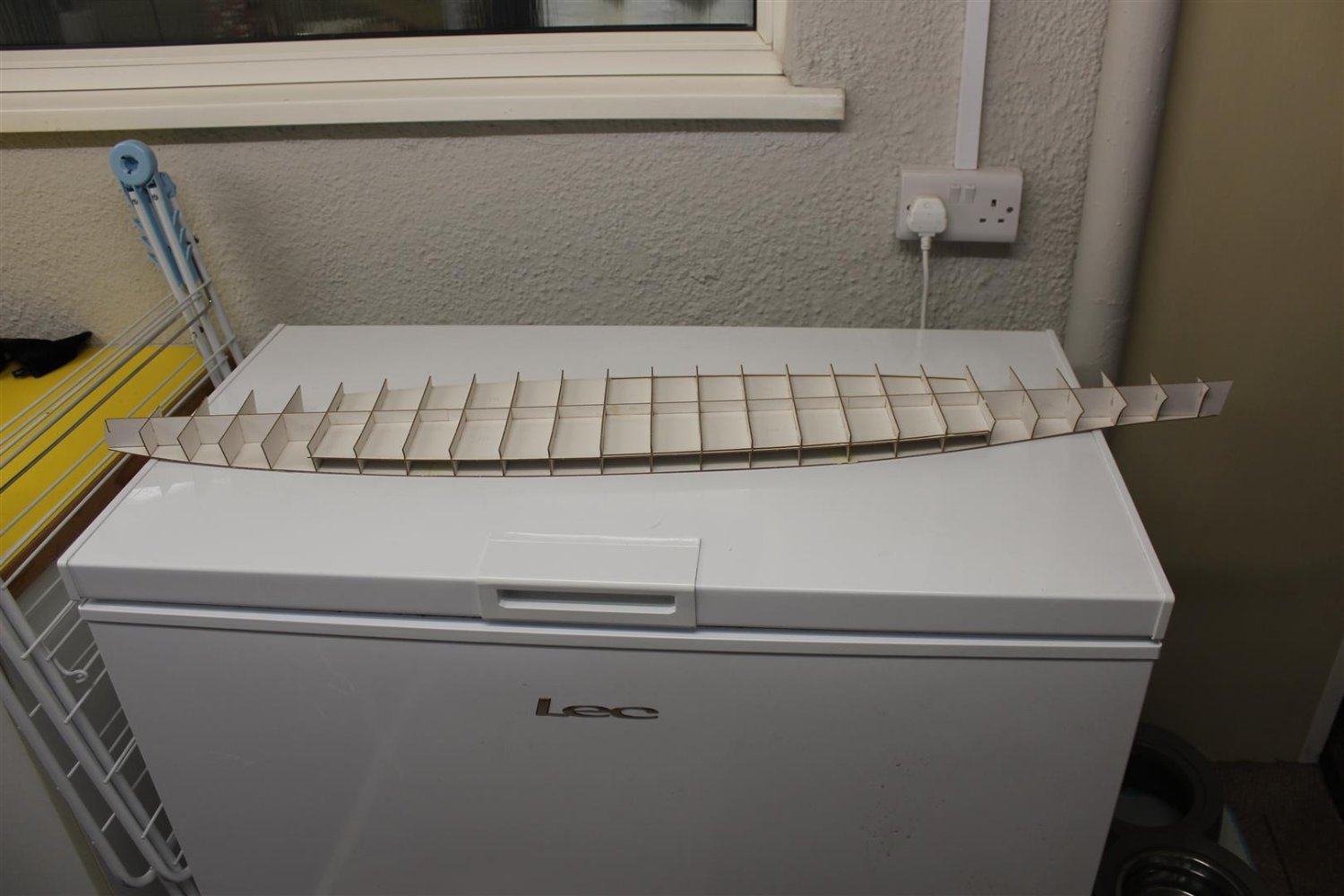
a few photos to show contents and a start has been made, yep bigger than the freezer


-
after the accident yesterday with the SD14, i still wanted to continue with the 90 day group build i was taking part in on another forum, i had bought this incase the SD14 wasnt allowed due to being a 1/3 of a kit
anyway i started it tonight and see how i get on, its not the same as the Marcle kit, this actually has some detail in it
taken from wikki

HMS Prince of Wales was a King George V-class battleship of the Royal Navy that was built at the Cammell Laird shipyard in Birkenhead, England. She had an extensive battle history, first seeing action in August 1940 while still being outfitted in her drydock when she was attacked and damaged by German aircraft. In her brief but storied career, she was involved in several key actions of the Second World War, including the May 1941 Battle of the Denmark Strait where she scored three hits against the German battleship Bismarck, forcing Bismarck to abandon her raiding mission and head to port for repairs. Prince of Wales later escorted one of the Malta convoys in the Mediterranean, and then attempted to intercept Japanese troop convoys off the coast of Malaya as part of Force Z when she was sunk on 10 December 1941, two days after the attack on Pearl Harbor.
She was sunk alongside her consort, the battlecruiser HMS Repulse, by Japanese bombers when they became the first capital ships to be sunk solely by air power on the open sea, a harbinger of the diminishing role this class of ships was subsequently to play in naval warfare. The wreck of Prince of Wales lies upside down in 223 feet (68 m) of water, near Kuantan, in the South China Sea.
-
just watched, very interesting


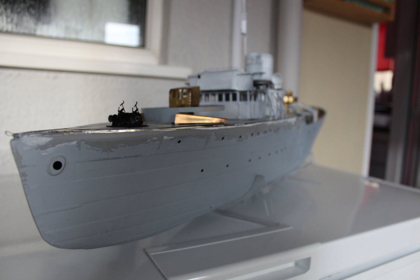
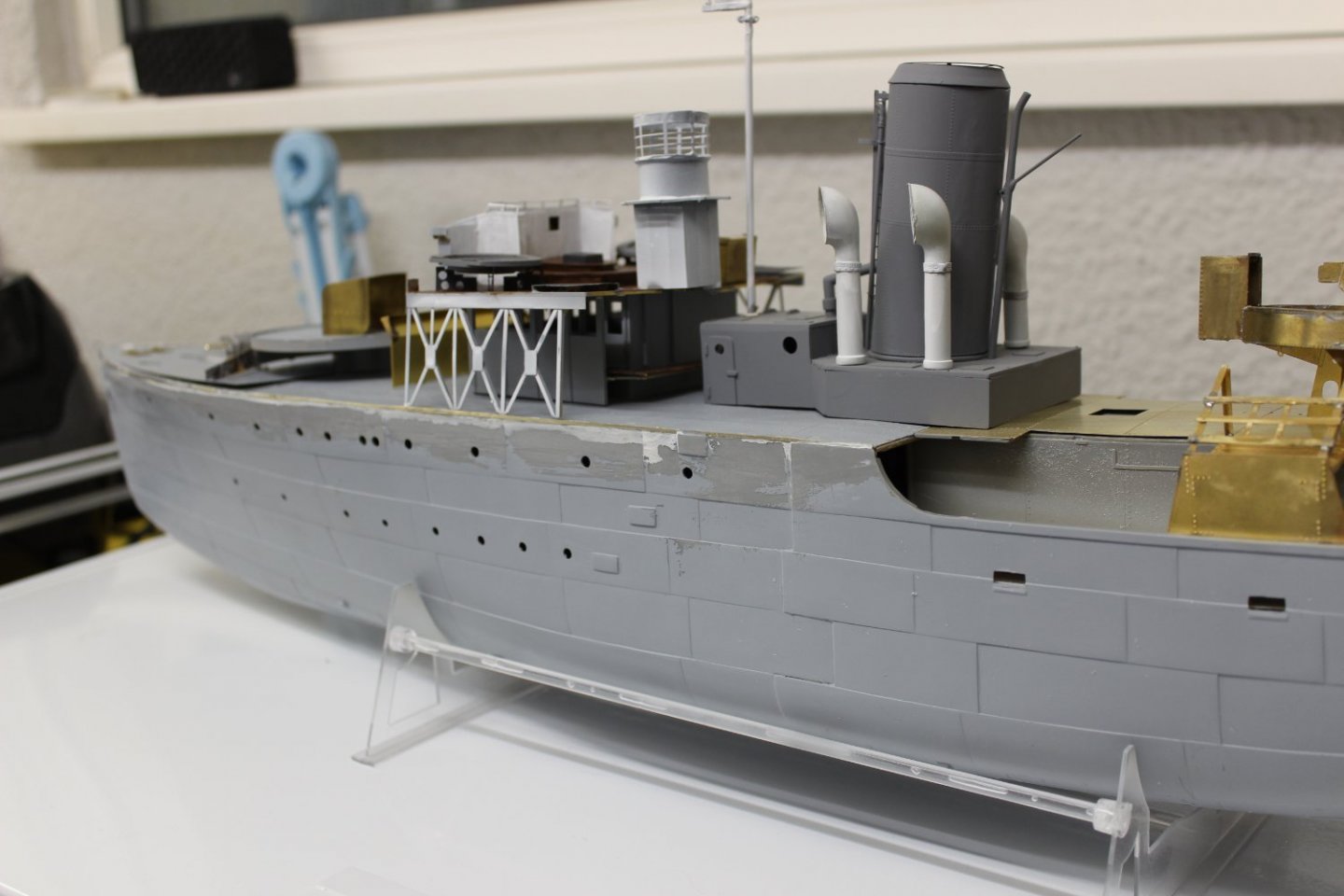
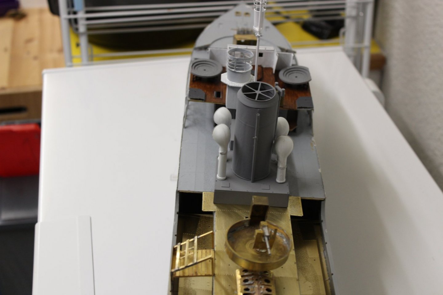
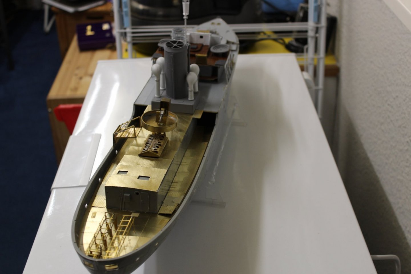
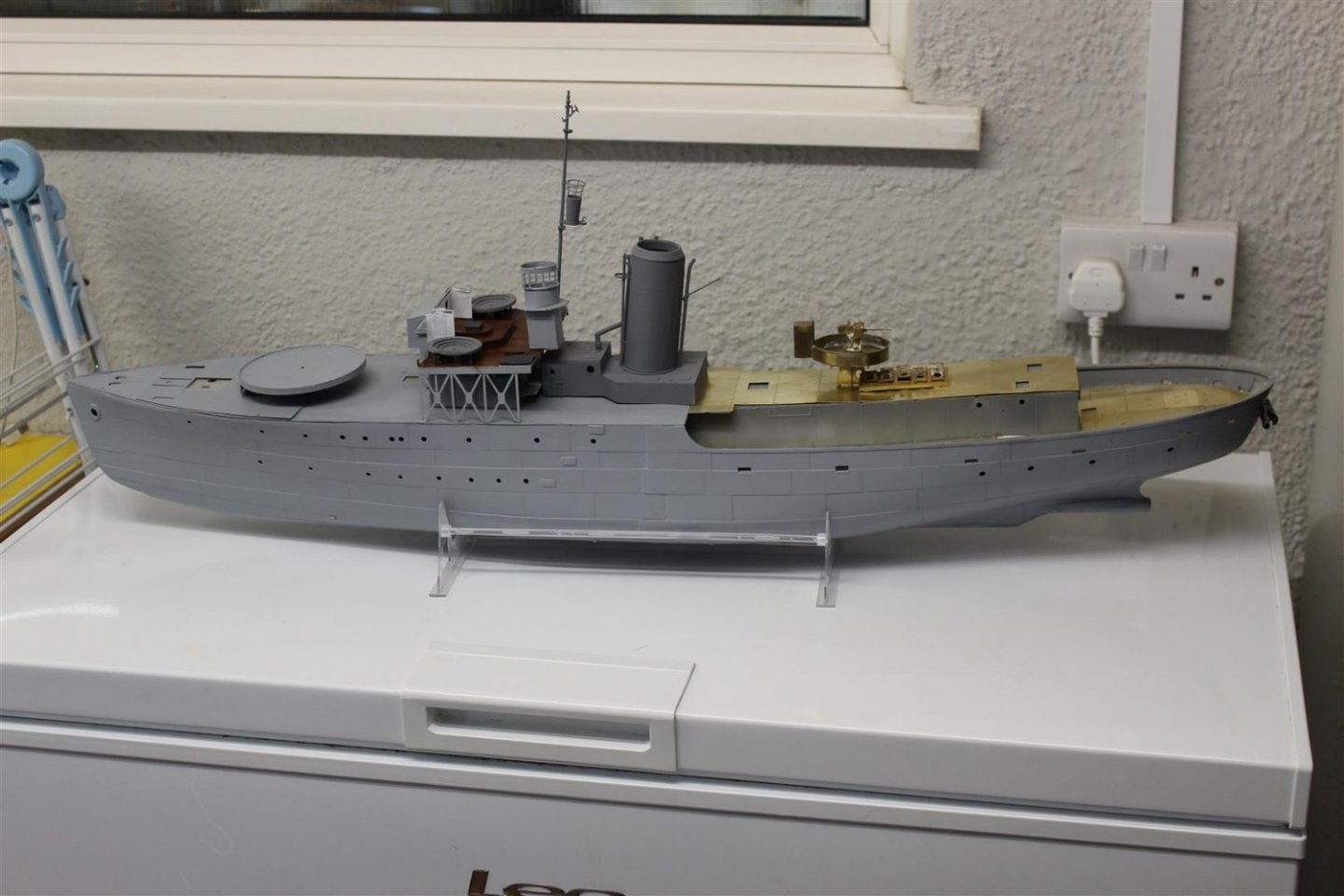
Bluebell by Kevin - Revel - 1/72 - PLASTIC - Flower-class corvette with GLS upgrade - restarted Jan 2022
in - Kit build logs for subjects built from 1901 - Present Day
Posted · Edited by Kevin
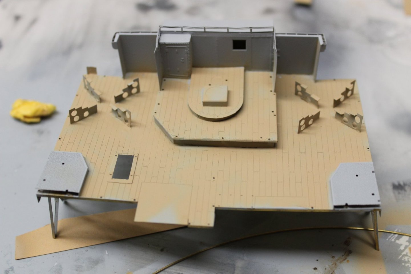
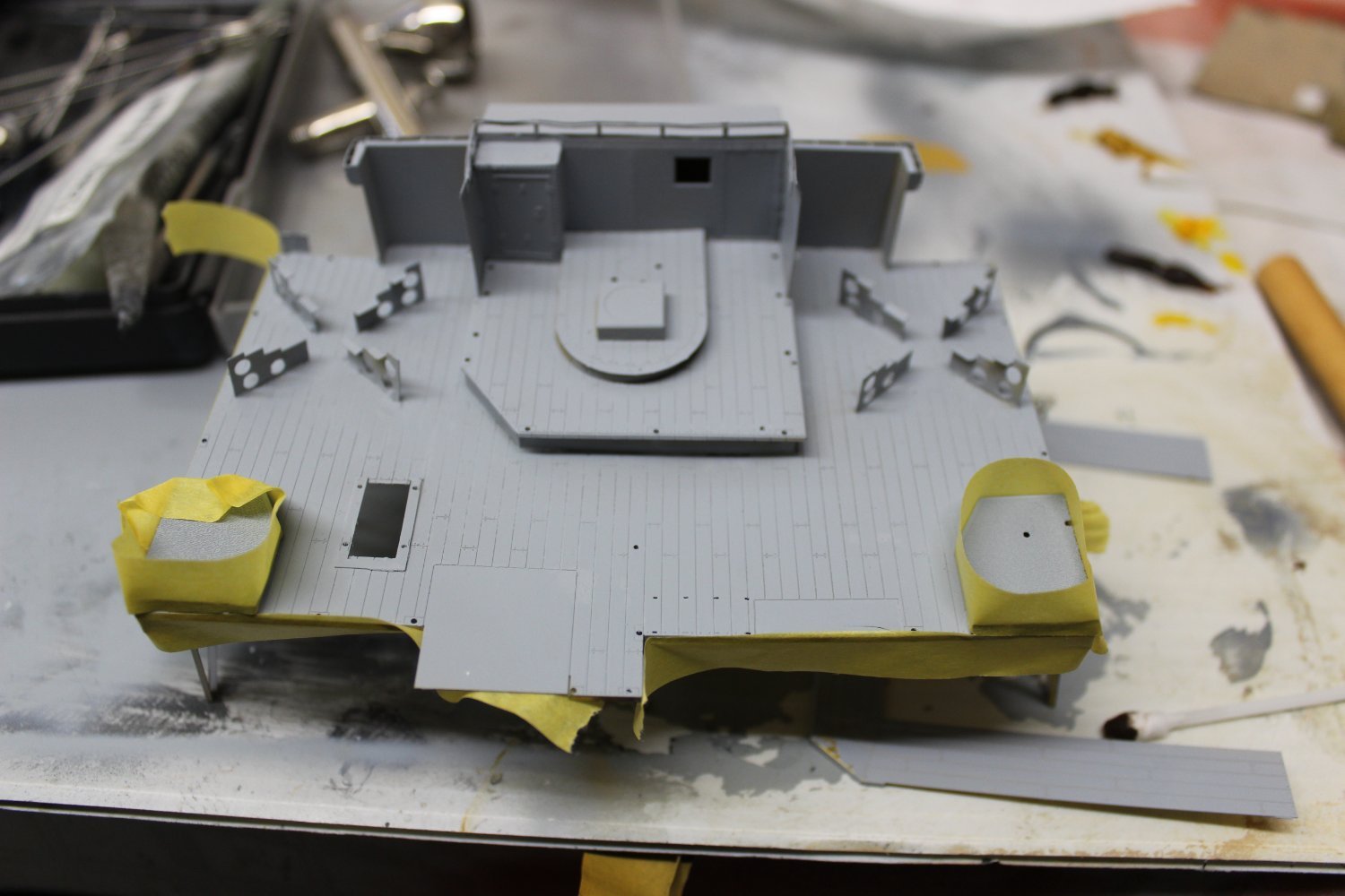
good evening everyone
thank you for comments and likes
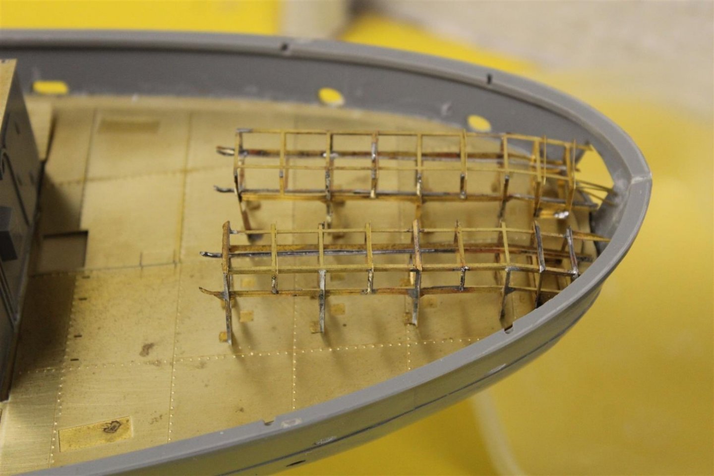
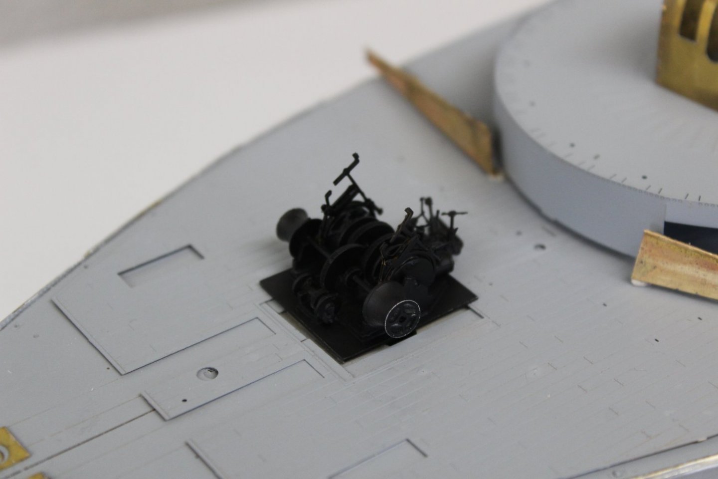
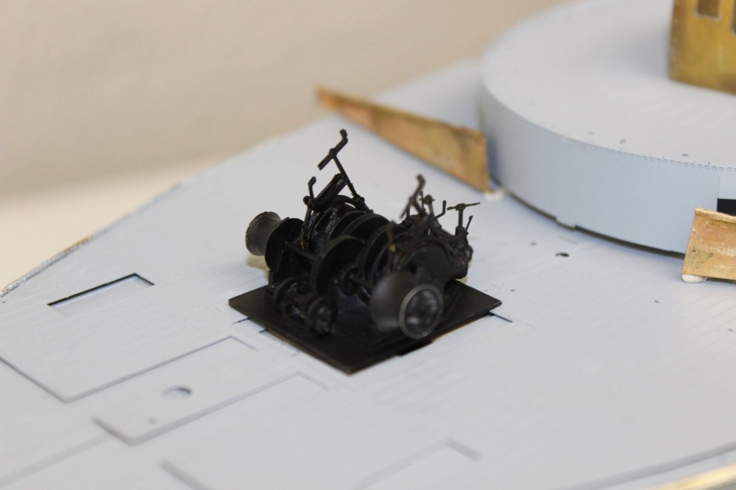
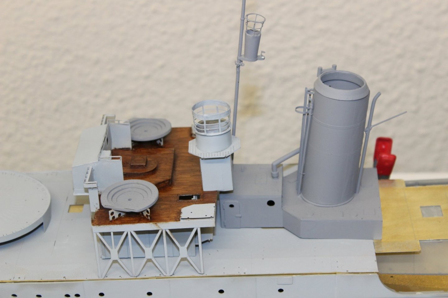
the depth caharge racks, i primed in red, thinking (incorrectly) that they are finished in a dark colour, they were redone in white primer
the lockers are from the kit with the exception of the skylight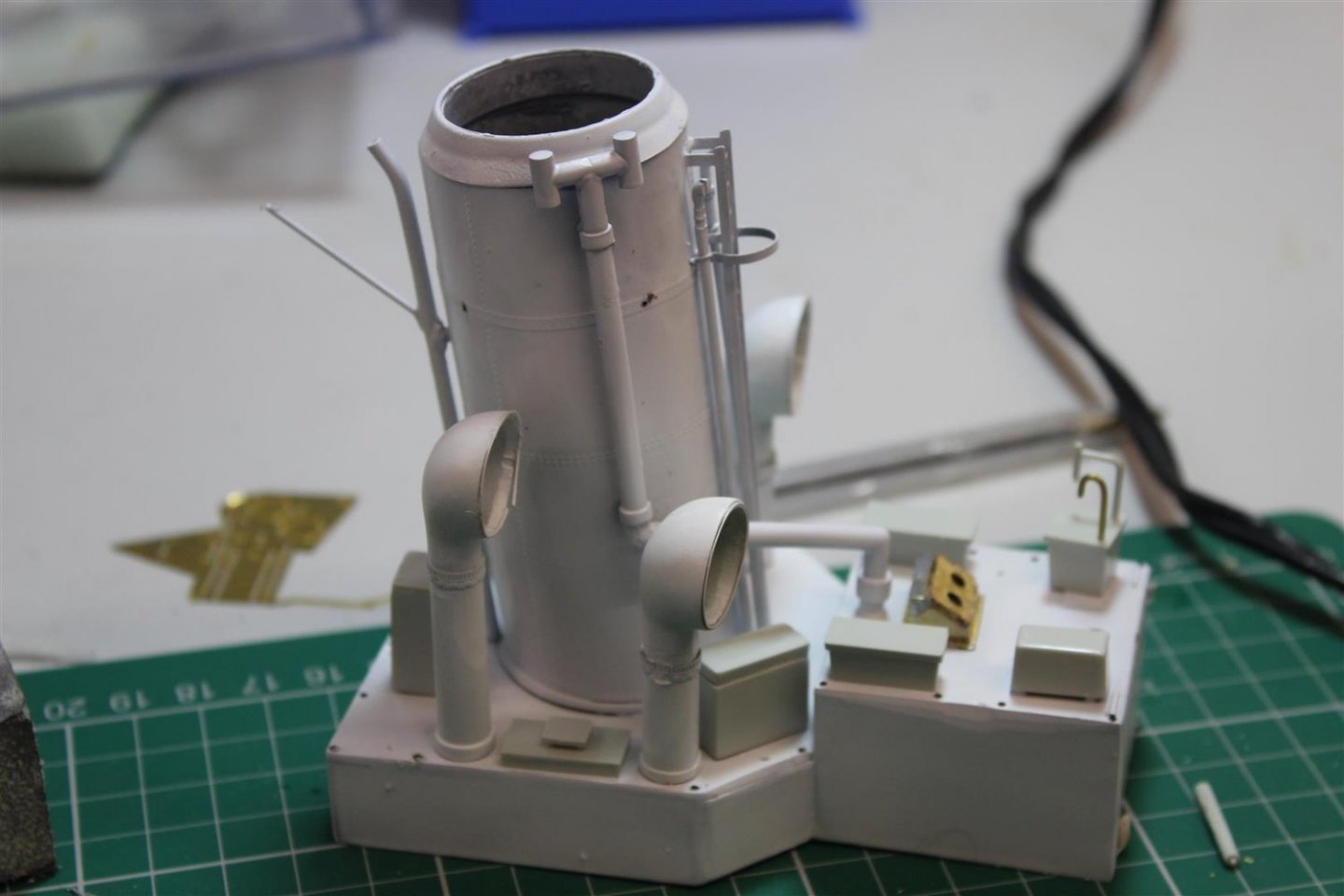
i continue to remove the hull to top deck seam line, but it is going