Maury S
-
Posts
1,490 -
Joined
-
Last visited
Content Type
Profiles
Forums
Gallery
Events
Everything posted by Maury S
-

Echo by Maury S - FINISHED - Cross-Section
Maury S replied to Maury S's topic in - Build logs for subjects built 1751 - 1800
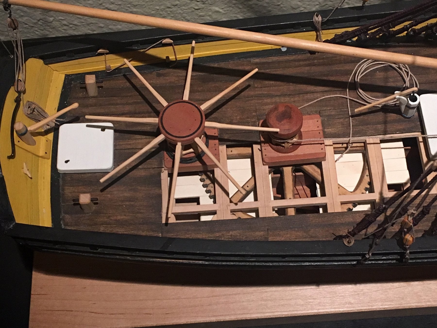
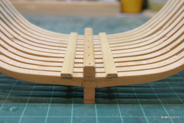
After sanding and sanding I finally got rid of all the pencil marks. Some filler pieces cut, other high spots sanded down. Final result seems that some sections of the frames seem very thin. Finish sanding with 220 grit, then 320. Keelson sanded to 12" x 12", and top corners sanded to a 45 degree angle. The center at every other frame was marked, tapped with an awl and drilled wtih 0.002 drill (#75?) for the bolts. The bolts are actually 0.0018" black monofilament line (thanks to EdT). Limber strakes sanded to 4" and boards cut to 12". The rabbet had to be cut...blade on my Proxxon saw set to just about 1" (@ sacle) and then the piece run thru. Good result. The other top corner sanded to a 45 degree angle (how do you type the little 0 forthe degree symbol?). Spacers cut to 11" and the limber strakes sanded to 320 and glued in place. The dark marks under the ends of the keeson and strakes are shadows from a very slight overhang that needs to be sanded down. The entire model has taken a very rigid setting...not nearly as flimsey as it was before the lastest additions. Maury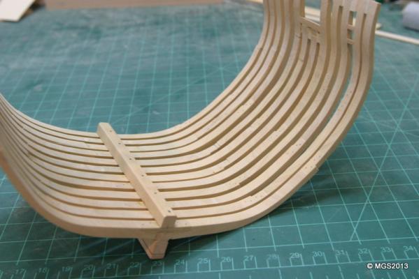
-
Echo by Maury S - FINISHED - Cross-Section
Maury S replied to Maury S's topic in - Build logs for subjects built 1751 - 1800
More rough fairing. The glue on the spacers of some frames has popped loose a few times. Delays things while new glue dries. So far I'm mostly faired down to 120 or 150 grit. Next round is 220 then 320. I'm thinking about how I'm going to trim the tops of the frames to the final level. Rough sanding creates too much vibration. After I re-mount it on the building board and mark the proper lines of the tops of frames, I'm leaning to my razor saw, then finish sand. Maybe that should wait 'til there are some battens installled up high? Maury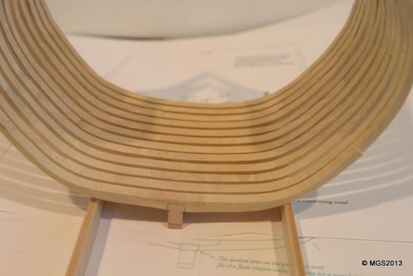

-
I used Aspen (from Hobby Mill) for the hull and deck planking on my Fair American. I wanted a white wood (no paint on her) and Jeff at Hobby Mill convinced me it would be whiter than the Holly. Not sure I would use it for framing!. Color was the ONLY reason I chose it. Maury
-
Echo by Maury S - FINISHED - Cross-Section
Maury S replied to Maury S's topic in - Build logs for subjects built 1751 - 1800
Thanks Greg. There is a sound to the faired section when all is right. Maury -
Echo by Maury S - FINISHED - Cross-Section
Maury S replied to Maury S's topic in - Build logs for subjects built 1751 - 1800
I've started roughly fairing up the frames. Sanding with 80 grit, then 120 grit. I clamped a piece of 1x2 to the workbench, extending out about 8". It provides a very stable base for sanding by putting resistance on the opposite side I'm working on. Vibration is still a problem. The glue for the spacer at the top of frame 5-aft has broken loose a couple of times. I've had to build up a few low spots by cutting a piece of the same thickness material to match a frame curve, cutting it thinly on the scroll saw then glue in place. Almost impossible to find after sanding. I'm really surprised at the amount of high and low areas considering how close (I thought) I was on the framing plans. Maury
-
Echo by Maury S - FINISHED - Cross-Section
Maury S replied to Maury S's topic in - Build logs for subjects built 1751 - 1800
Installing the frame extensions on top of the gunport sill. They are fiddy things since you have to cut part off the bottom and part off the top from the pieces saved when installing the 2-a and 3-f frames. Then you have to get the bottom sanded for the proper cant to the part. The "O" mark indicates it's the outer side of the piece. The braces / spacers (out of focus ends) are the same thickness as material used as spacers below. That insures a plumb installation. One side at a time and then I'll remove the braces and cut pieces off for the temporary spacers. Careful checking of the plan reveals that a good 1/8" will have to be cut or sanded off the frame tops (see thin pencil line on ajacent frames) so I'm trying to keep the extensions close to that height. They are delicate so rough cutting or sanding has to be limited. Maury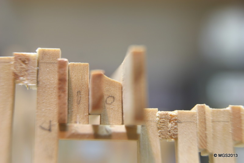
-
Echo by Maury S - FINISHED - Cross-Section
Maury S replied to Maury S's topic in - Build logs for subjects built 1751 - 1800
Greg, When do I start thinking about sanding sealer or poly fininsh? Do I finish the between sides of the frames now or wait til after the faring? Also, when I was sanding the openings for the gunport sills, there was enough vibration to loosen the piece a bit from the building board. I don't want to tear up the threads in the keel. Is it OK to take it off the board for sanding? Maury -
I have a small electronic device that emits a beeping tone that drives rodents and insects away. Seems to work since I've had no mice eating any wiring or tubing either in the garage or attic. Ebay for very little money. Maury
-
Echo by Maury S - FINISHED - Cross-Section
Maury S replied to Maury S's topic in - Build logs for subjects built 1751 - 1800
Thanks for the comments. Maury -
Echo by Maury S - FINISHED - Cross-Section
Maury S replied to Maury S's topic in - Build logs for subjects built 1751 - 1800
Thinking ahead to the time I remove the interim spacers..particularly the ones under the gunport sill...will there be a problem using isopropyl alcohol to get them out (loosening the sills)? Maury -
Echo by Maury S - FINISHED - Cross-Section
Maury S replied to Maury S's topic in - Build logs for subjects built 1751 - 1800
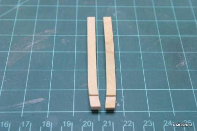
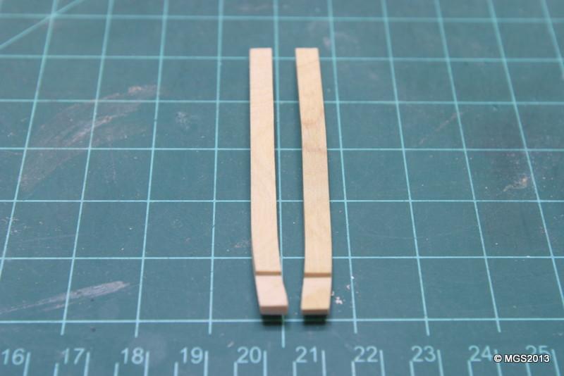
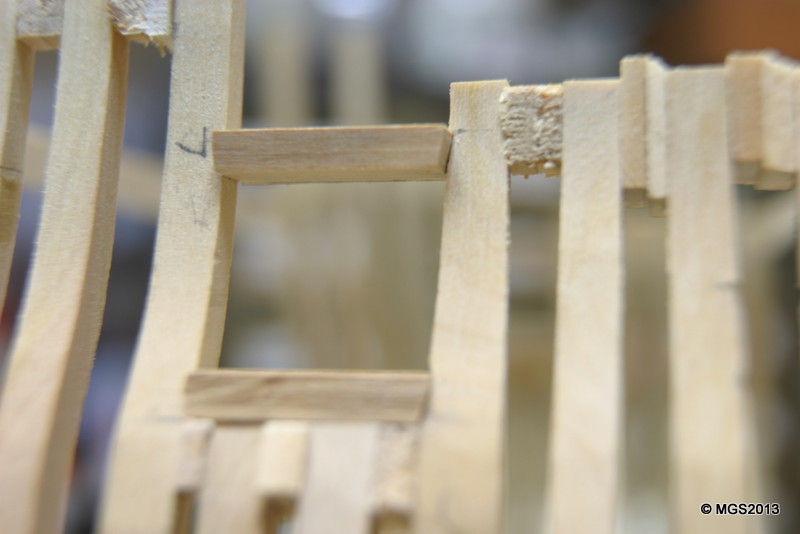
Work on the sills. I had a bit to take off the two lower frame parts so a new sanding stick with some 80 and 120 grits made short work of the job. The vibration of sanding loosened the boat from the building board a bit. Next time I sand like that I'll put a beam across the frames and clamp it down. I made a trial sill on some scrap. It went easier than I had feared. After getting the length about right, I sanded the pieces on an angle to get the two shapes. A couple of bad ones (too much of an angle, a hair too short) but two little pieces into the trash is nothing.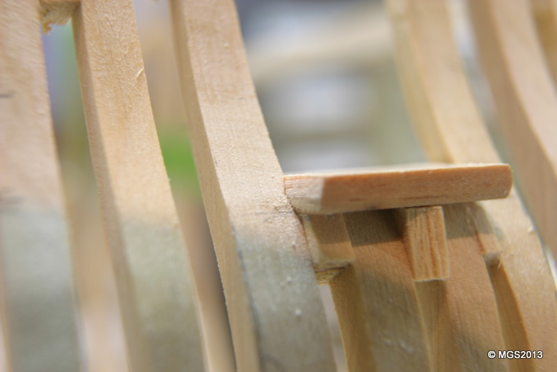
-
Echo by Maury S - FINISHED - Cross-Section
Maury S replied to Maury S's topic in - Build logs for subjects built 1751 - 1800
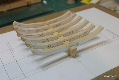
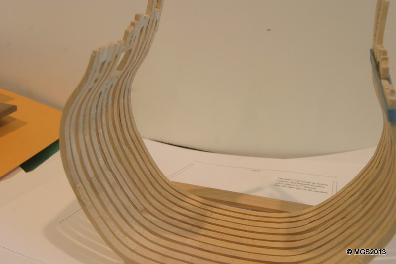
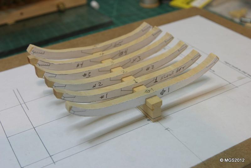
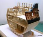
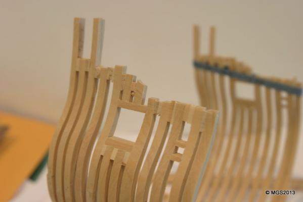
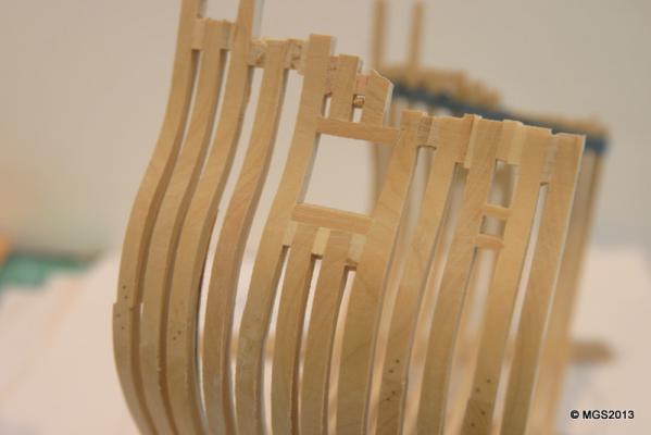
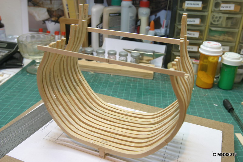
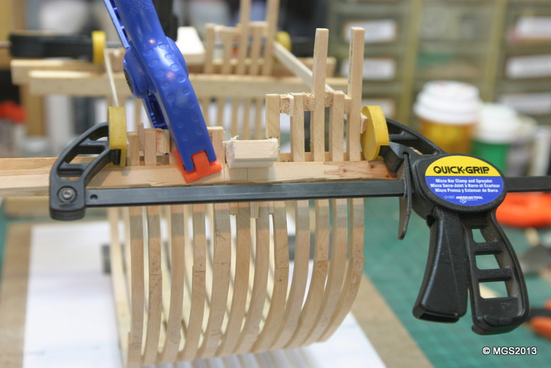
Frames all raised, plumb, square, even. First shot is with all the cross-braces still in place. The next is with all intermediate braces removed. The ones on the fore and aft ends are left in place being used to insure the frames at the ends are plumb. Last shot shows the carefully measured spacers between the frames being glued. I did the first four frames, then moved to the aft and did four spacers moving toward the center. Then I filled in the remaining. I held the frames fairly even with each other by running some stringers inboard and out (held with the blue clamp). I could slide the frames fore and aft without pushing them in or out. They are not faired yet, but it kept them in close position. Next up are the port sills. Very challenging. I suspect a lot more pieces for the scrap box. Maury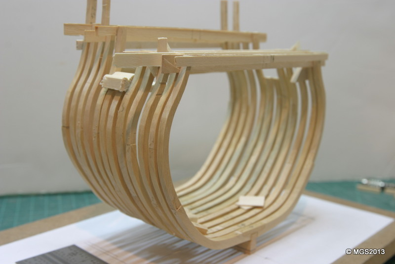
-
Echo by Maury S - FINISHED - Cross-Section
Maury S replied to Maury S's topic in - Build logs for subjects built 1751 - 1800
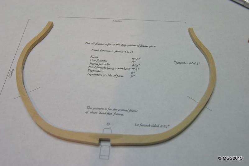
Frame 3-Aft repaired and raised. Spacing is set versus the 3rd frame forward (2-fore) so the gun port is the proper width. The frame was temporarily set, notches marked to match the heights of the forward frame and then removed so the notches could be cut. Now glued, braced and drying. Maury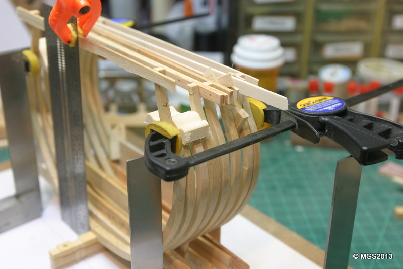
-
Echo by Maury S - FINISHED - Cross-Section
Maury S replied to Maury S's topic in - Build logs for subjects built 1751 - 1800
While linig up the (temporary) cross support on top of frame 3 Aft, I found it not lining up with the plan. Seems when I accidently broke it at the lower chock and re-glued, it wasn't lined up properly. Rather than re do the whole frame, it seemed like just the sections above the lower chock were out of line. Part of a paper towel, soaked in 91% Isopropyl Alcohol then wrapped with Saran Wrap for and hour and it cape apart easily. Trimmed one side and re-glued. Maury -
Very nice planking! Maury
-
Echo by Maury S - FINISHED - Cross-Section
Maury S replied to Maury S's topic in - Build logs for subjects built 1751 - 1800
Greg and Druxey, Thanks for the input. I cut the notches for the port sills while the frames were flat on the building board (Fore frame first, then temporarily install the aft frame and mark carefully) and thought I'd do the same for the scuppers. I'll hold off for now. More progress last evening...two more frames raised...no pictures since the alignment process is the same as the last pictures posted. The Byrnes thickness sander is real handy for getting the frame spacers to the exact thickness. Maury -
Greg, I know you poste a pic. of Speedwell all framed up. I can't locate it. Can you provide a lnk or reference? Thanks Maury
-
Echo by Maury S - FINISHED - Cross-Section
Maury S replied to Maury S's topic in - Build logs for subjects built 1751 - 1800
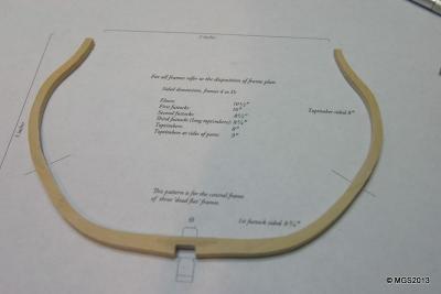
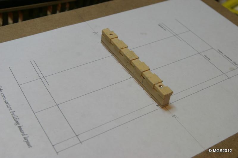
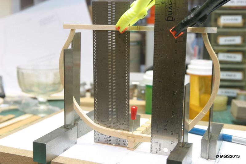
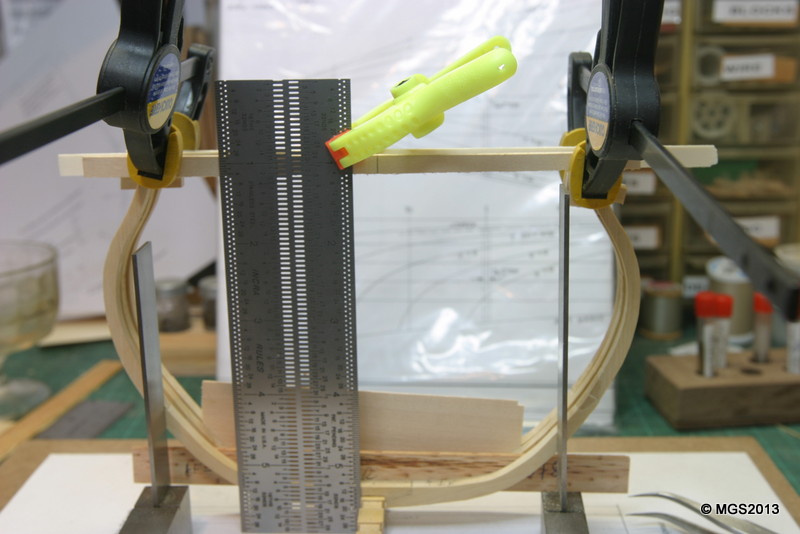
The frames are now set to be erected. A temporary cross member is glued across the top edge of the frame with marks lined up with the edge of the rising wood. Several squares are used to align with the building board and my Incra rule provides a plumb line from the rising wood to the mark on the cross member. Once the first (DF) frame is in place and the glue dry, I can procede with DF1, 1Fore and 1aft. I cut the notches for the sweep ports on DF1 and after it was in place, I dry-fitted 1fore and marked the tops and bottoms of the notches. THe frame was then removed, notches cut and replaced on the keel. Specially-sized spacers are inserted between frames while the glue dries. Greg, on the framing plan, there is a horizontal line above the scupper-support "boxes". Does this define the inboard top of the scupper support? It's a pretty big angle so I want to be sure before I notch the next frame. Maury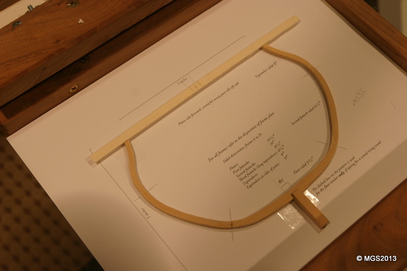
-
I searched quite a bit when building my Emma C. Berry. Tough to find, but I bought a set of "workers" from some rail road site...info lost when the log disapeared with the MSW server crash. You want a Guage One figure but if you find 1:35 that would be better. People were smaller 150 years ago. I have several figures left over. Send me a PM and I'll send pics. I'll give you any one you want. Maury
-
Yves, Nice work so far. You might want to sand off the laser burn from the deck frames, etc. You don't want that showing if you do not fully plank her deck, and it may impact the strength of the glue. Maury
-
Echo by Maury S - FINISHED - Cross-Section
Maury S replied to Maury S's topic in - Build logs for subjects built 1751 - 1800
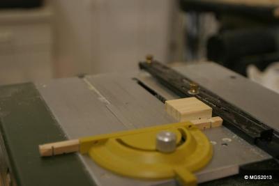
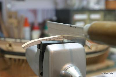
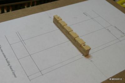
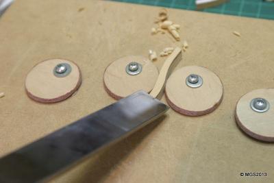
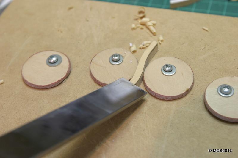
Slow progress. Frames now glued up. I'm tree-nailing thru all chocks for added support. I suspended a block off the end of the work bench to create a rigid support while "center-punching" the layout for the tree nail holes. Then they were all drilled (#76 drill bit). I recall an earlier discussion (I think Toni at the Echo Workshop) where the tree-nail layout was customarilly the upper nail was forward of the bottom of each pair. Now I have to pull a bunch of bamboo. Maury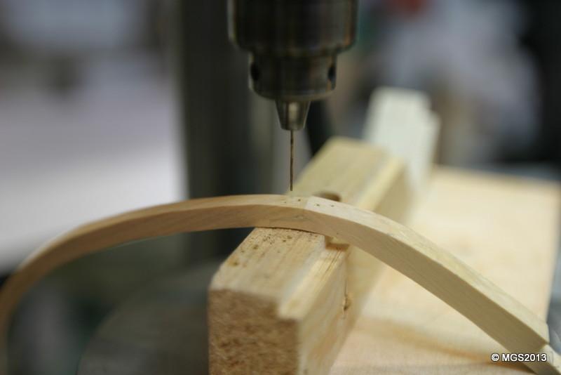
-
Echo by Maury S - FINISHED - Cross-Section
Maury S replied to Maury S's topic in - Build logs for subjects built 1751 - 1800
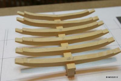
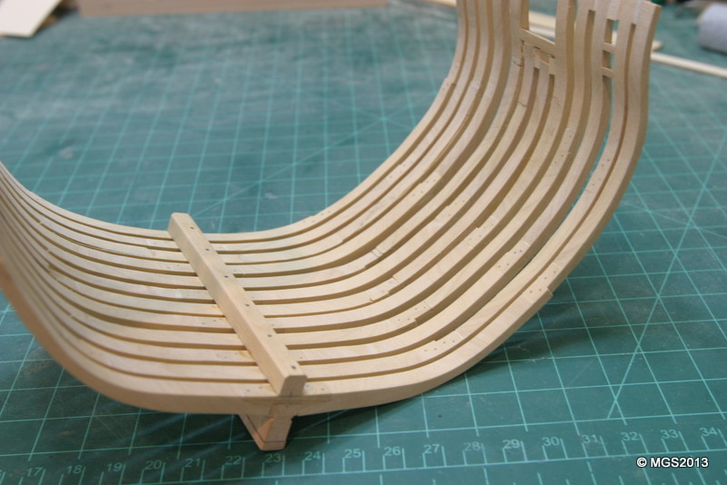
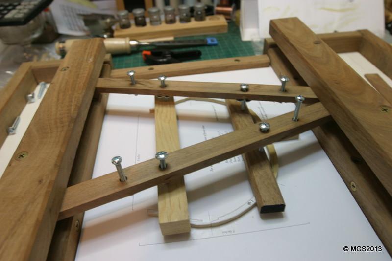
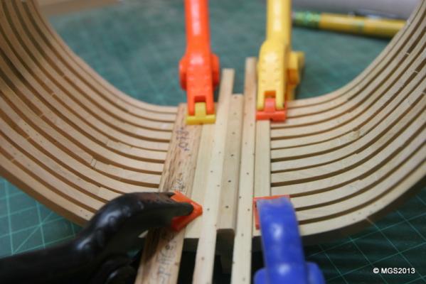
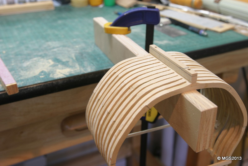
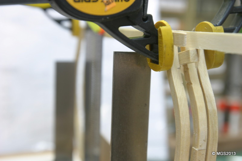
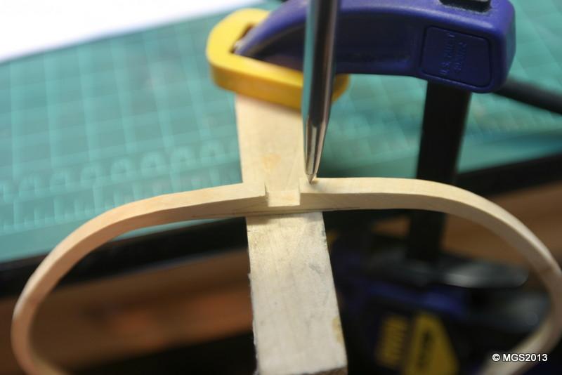
Druxey, The jig is right out of Ed Tosti's log. The upper parts on the two sides are fixed, providing resistance when the "battens" are inserted in the slots and the screws tightened, pushing down on the lower braces thus holding down the frame parts while the glue dries. Maury -
Echo by Maury S - FINISHED - Cross-Section
Maury S replied to Maury S's topic in - Build logs for subjects built 1751 - 1800
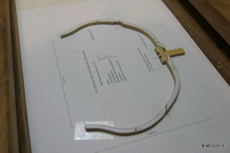
Here are some of the early pics. Just getting used to the new system...Boy I miss the lost files! Maury