fmodajr
-
Posts
869 -
Joined
-
Last visited
Content Type
Profiles
Forums
Gallery
Events
Everything posted by fmodajr
-
 Thanks Michael! I should have the davits installed by next weeks post. I've been following the very interesting discussions on your log! Clark, Mark, Kirill4 --thanks for the likes! Frank
 -
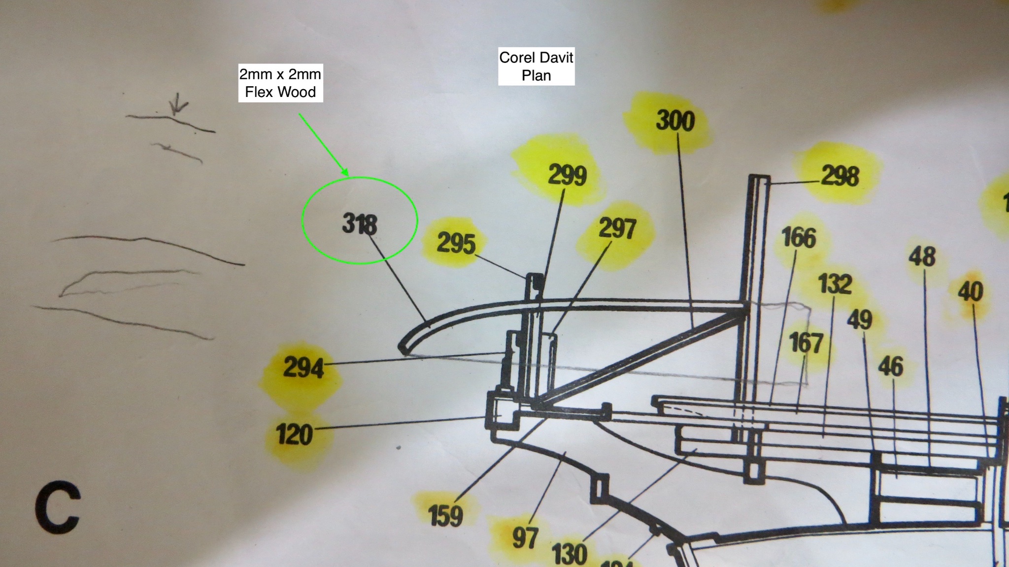
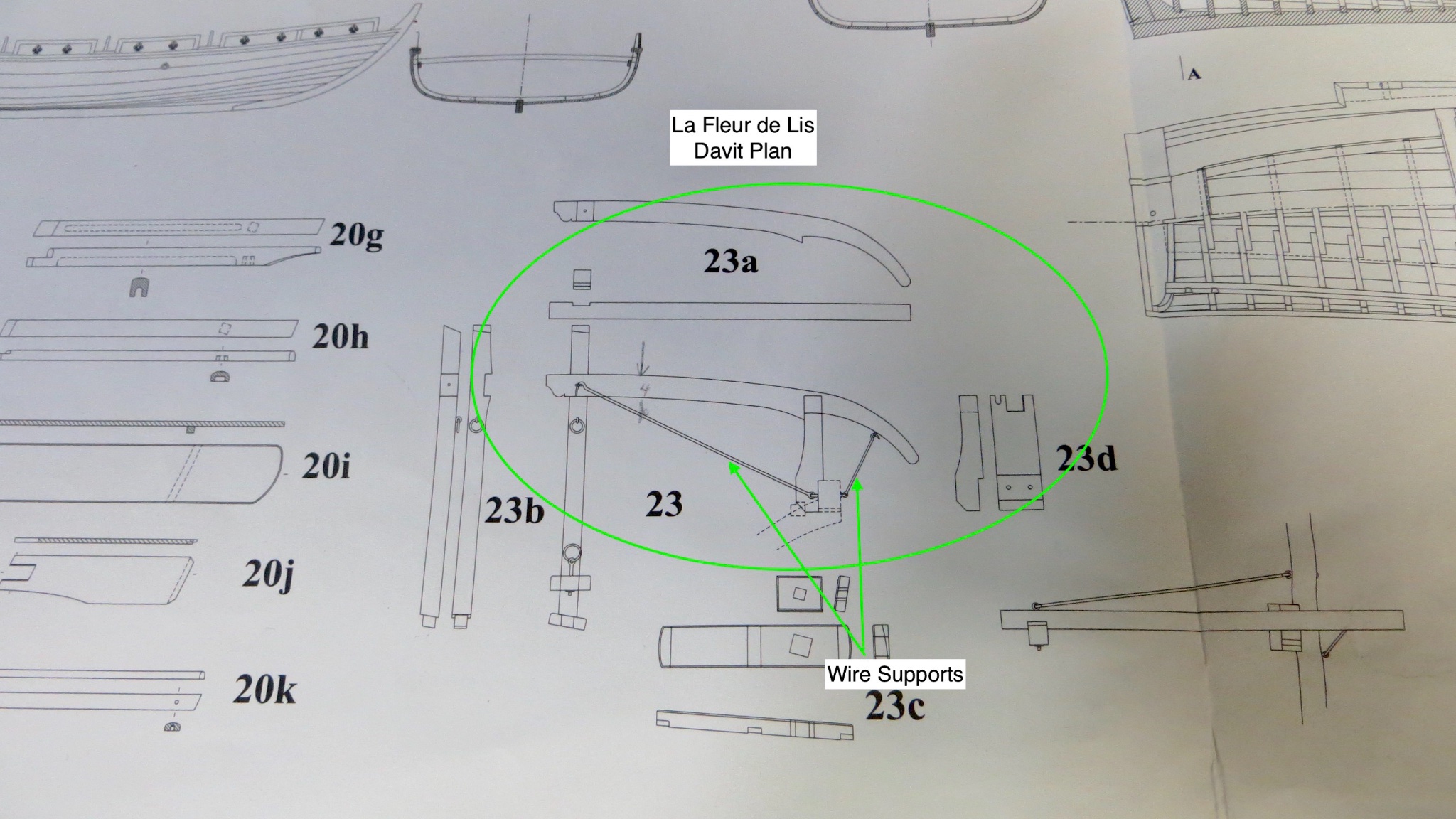
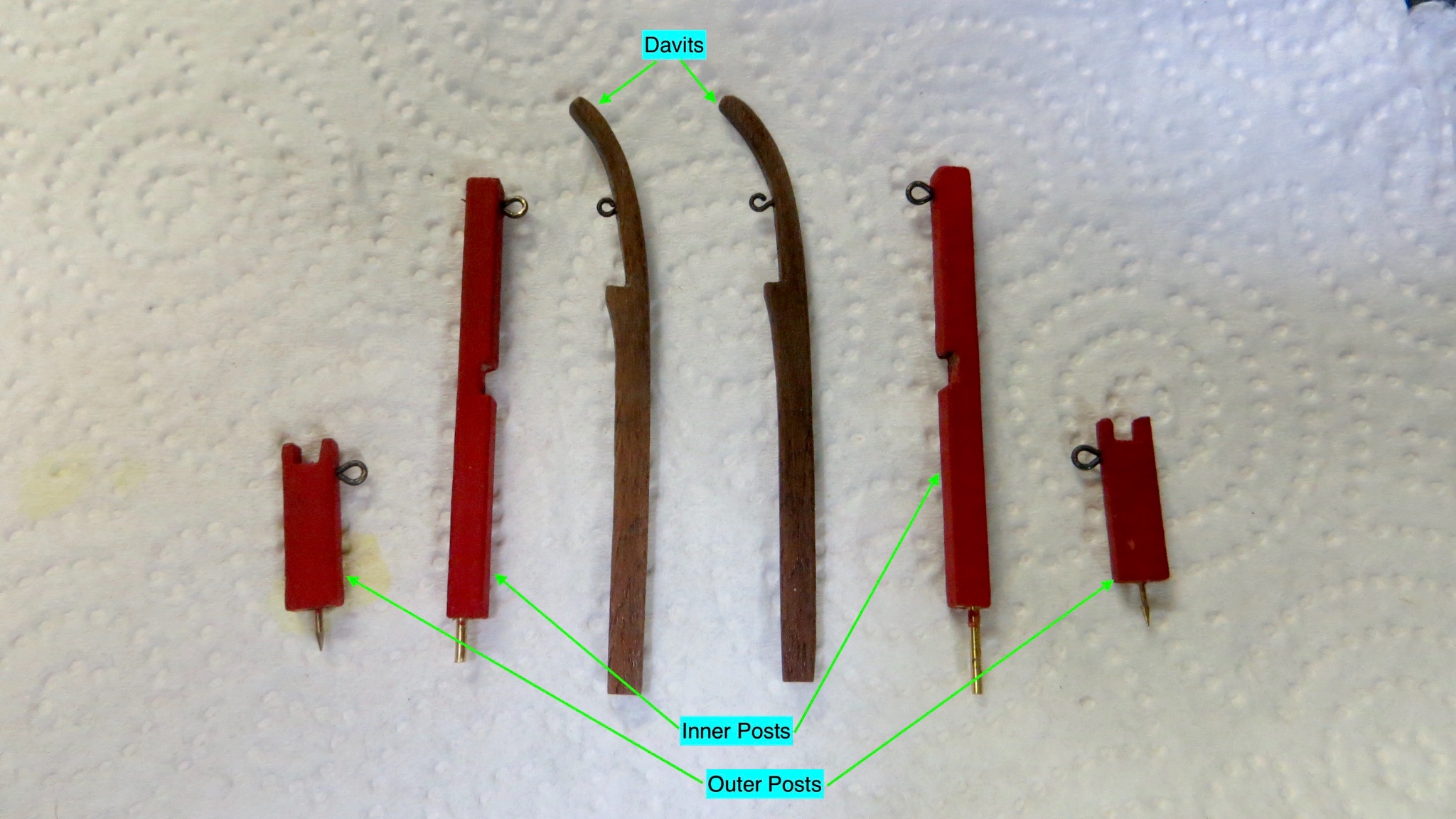
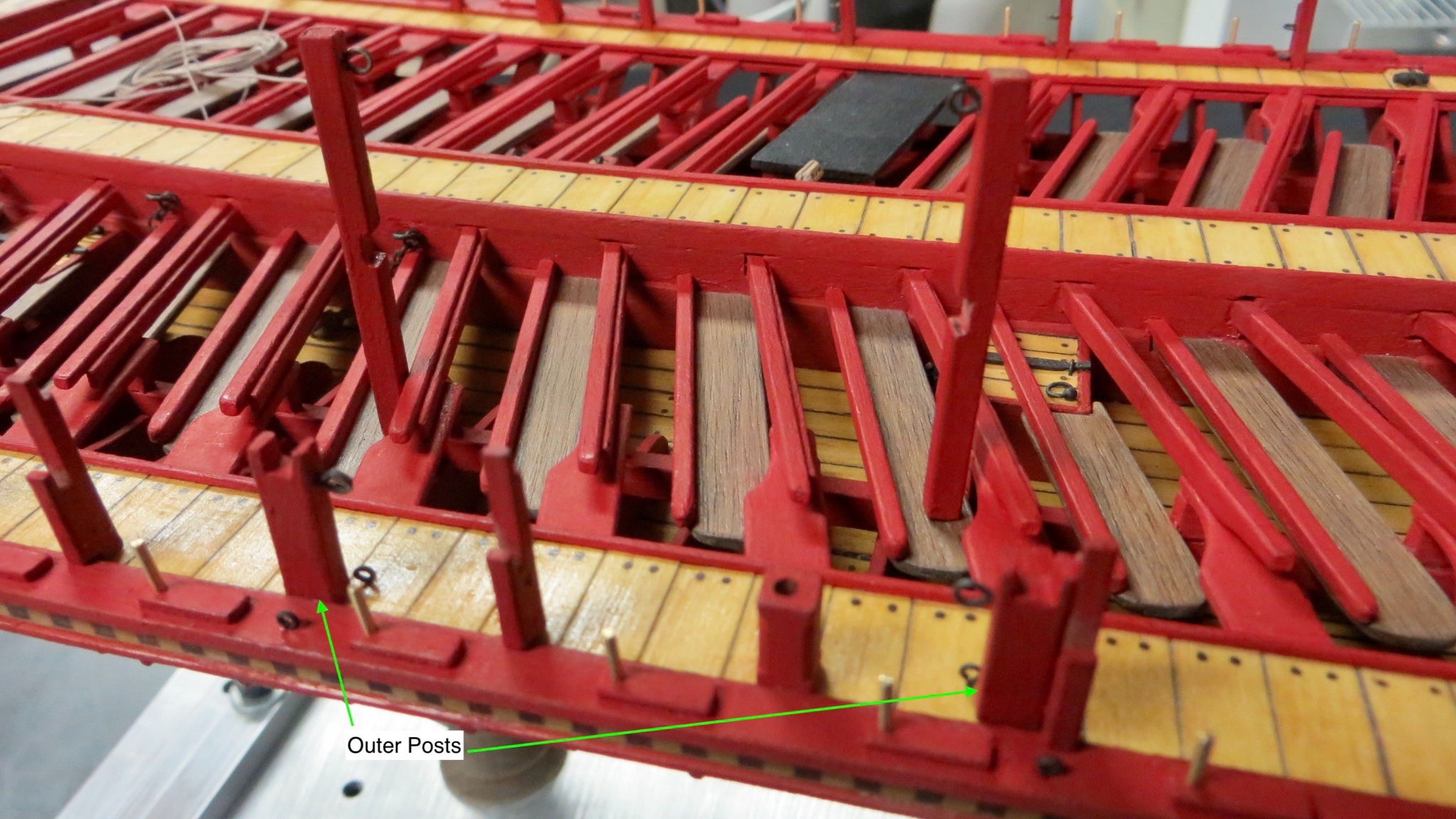
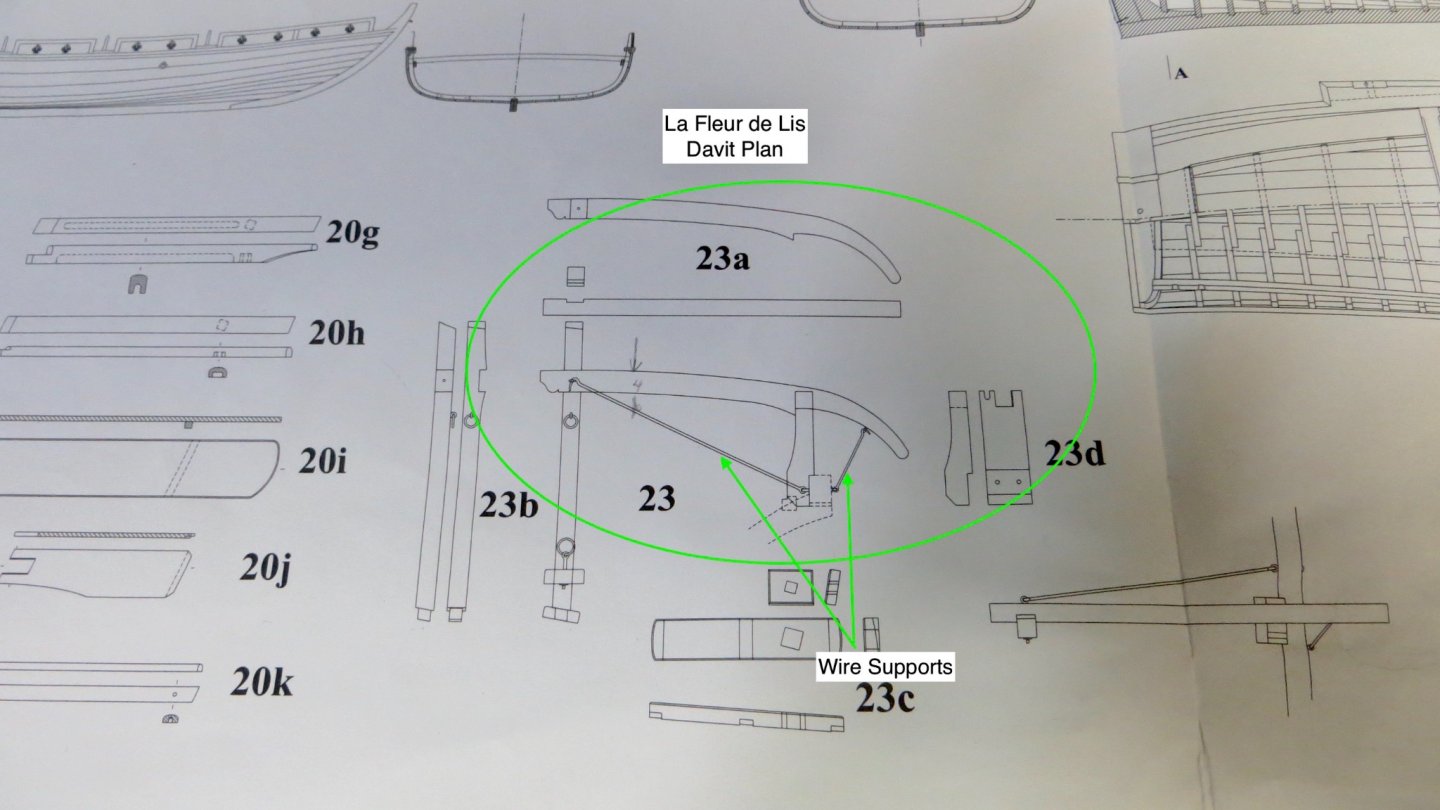
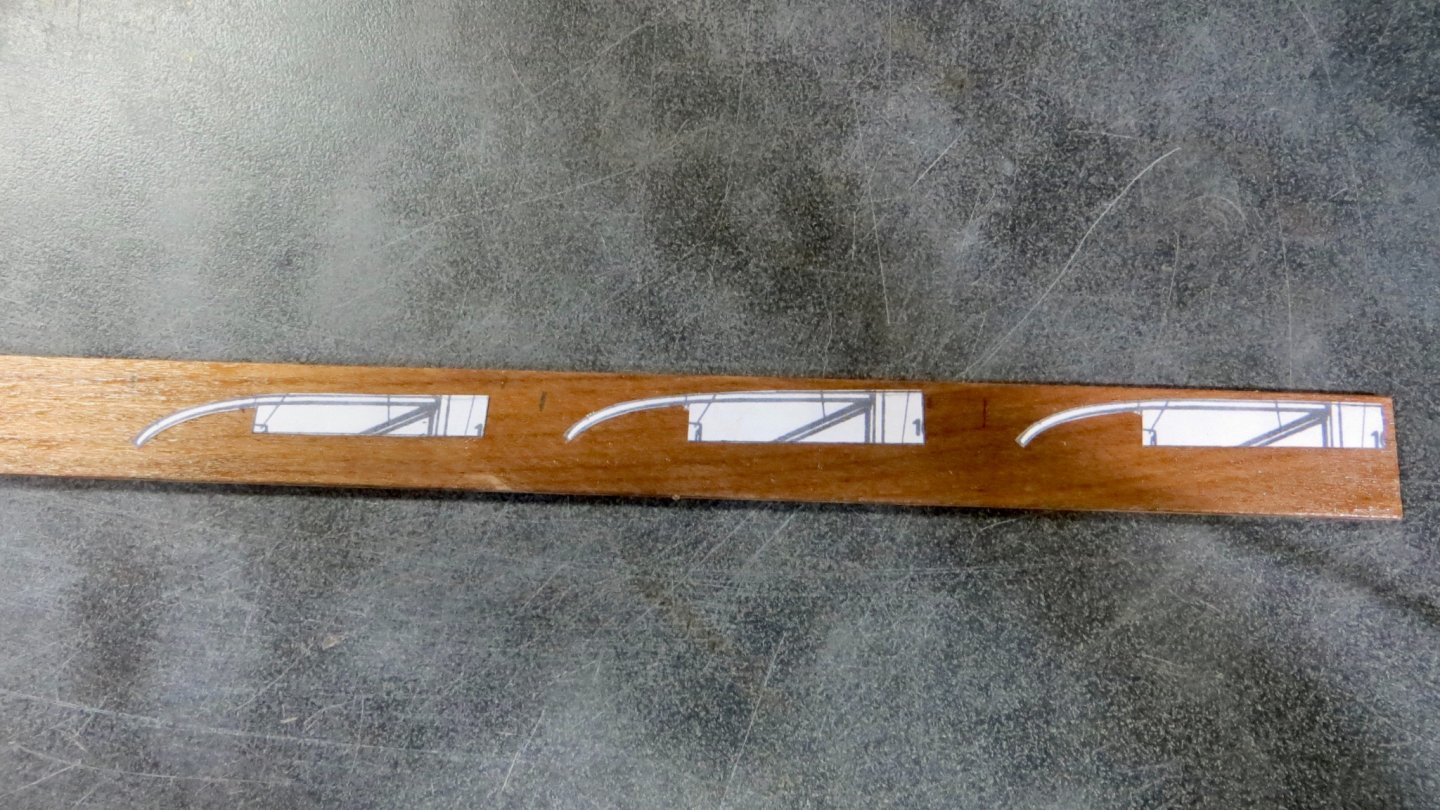
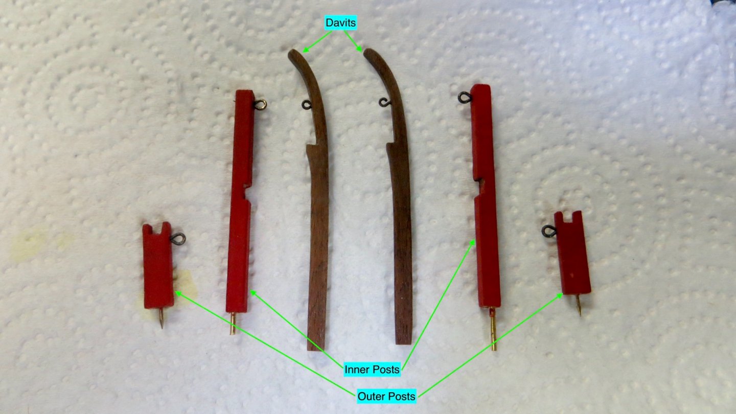
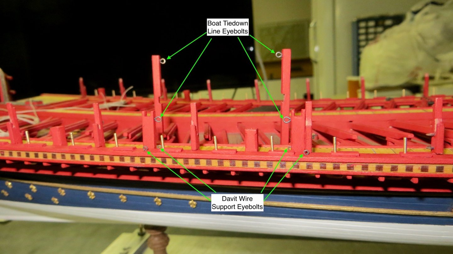
Hello, I have started to look at the davit area and davit posts on the starboard side of the model. The Corel plan, as shown below, shows a pretty simple plan. 2 Vertical posts (298 and 297) supported by a cross beam (300). Then the plans call to use a piece of the flexible wood in 2mm x 2mm size for the davits. The "La Fleur De Lis" davit plan is a little more complicated, detailed, and interesting. The davits are fitted onto the posts 23b and 23d. The davits are thicker for most of its length and are held onto the posts with what looks to be rods that are removable. I have tried to use elements of this plan. A piece of walnut was thinned to 2 mm thick and the curved section from the Corel plan used as a guide. The taller inner posts were cut and slotted to accept the davits and and the outer posts slotted for the outer end of the davit. The davits themselves were made to look a bit more like the plan on "La Fleur De Lis" The Inner and outer posts are attached to the model. The large eyelets shown are for the tie down lines of the long boat. The other smaller eyelets will be used for attaching the rods to hold the davits (As talked about in the photos above) My next steps will be to add a few deck cleats and rigging chains. Then attach the lower rail on the starboard side before adding the davits. Thanks for stopping by for a look!! Frank


- 510 replies
-
- 9
-

-
- reale de france
- corel
- (and 1 more)
-
The wood effect came out nicely! As did the chain plates. They were a pain for me to install. I barely made the slots big enough for the chain link to pass thru!! Frank
-
Thank you for your thoughts and for stopping by! Frank
-
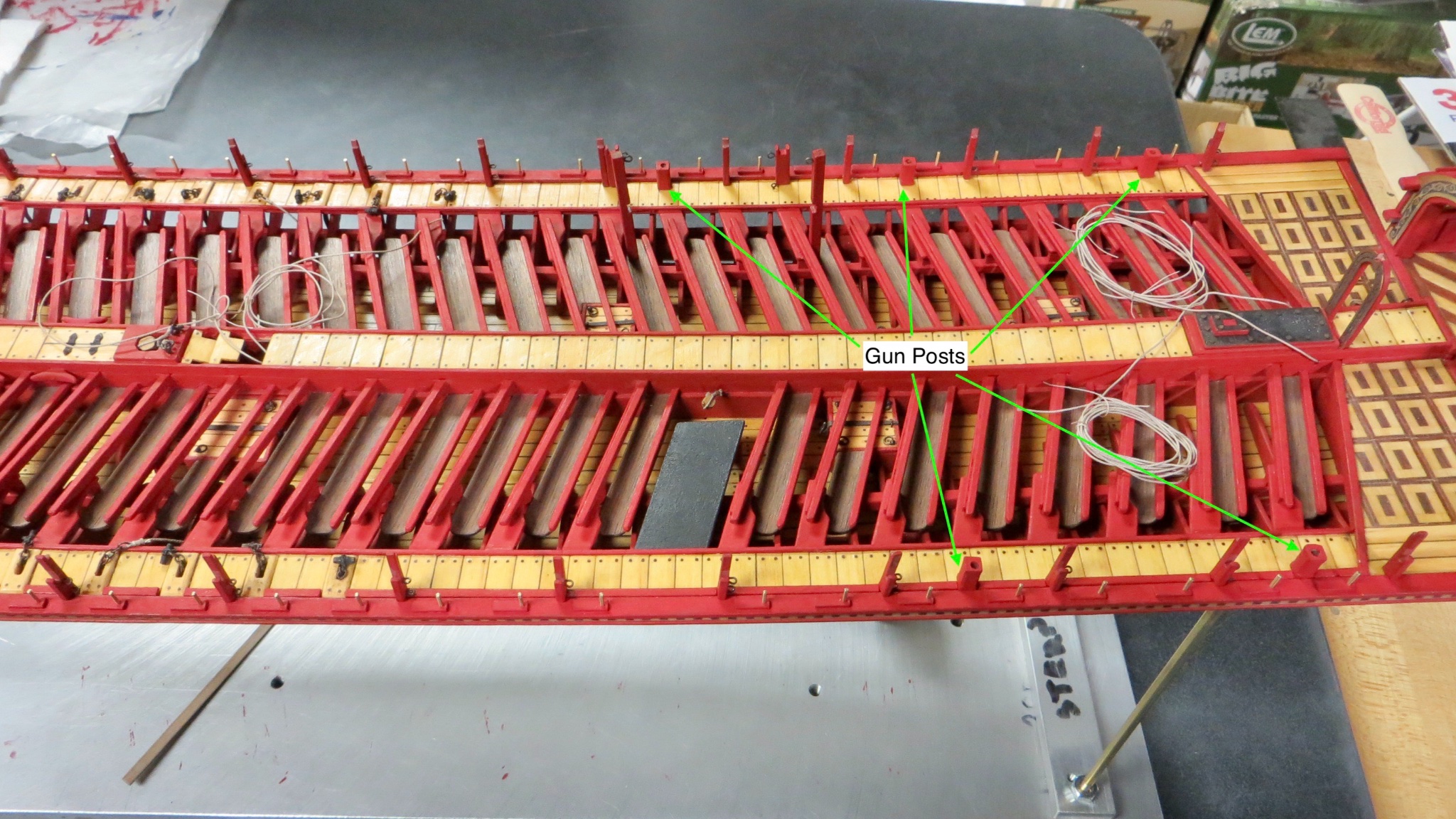
Hi Clark, thanks for your post. Yes, I checked each gun post to make sure the guns fit between the 2 railings. The posts are actually a lot smaller height wise than they seem on the Corel plan. Thanks for the warning! Frank
- 510 replies
-
- 1
-
-
- reale de france
- corel
- (and 1 more)
-
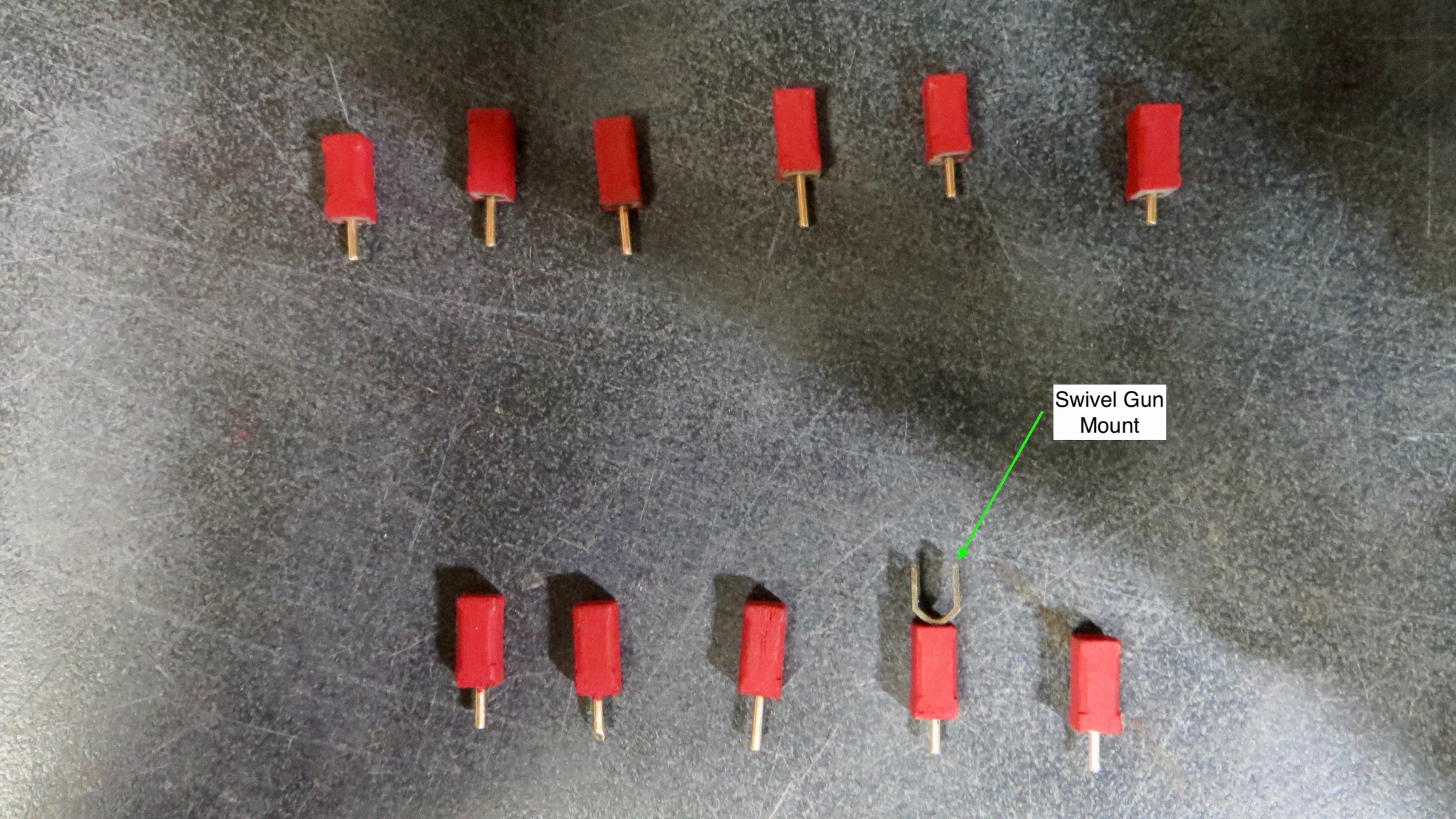
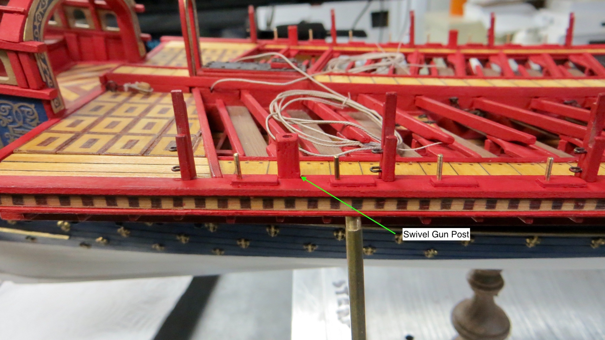
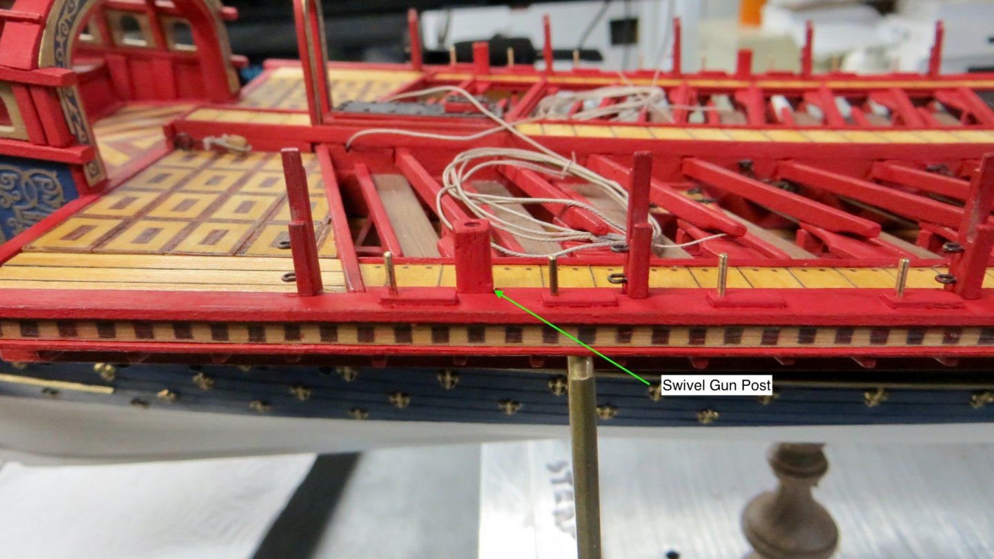
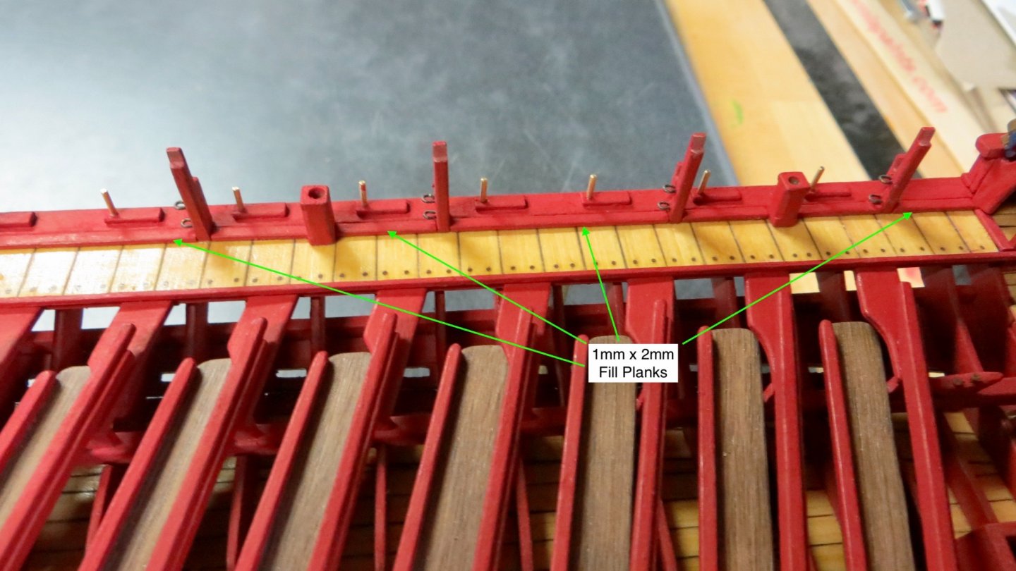
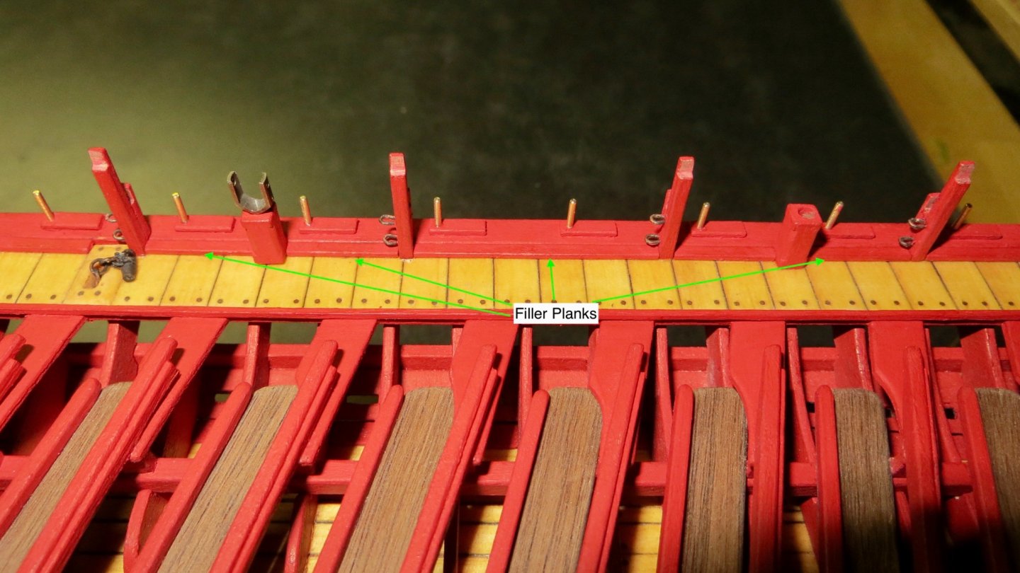
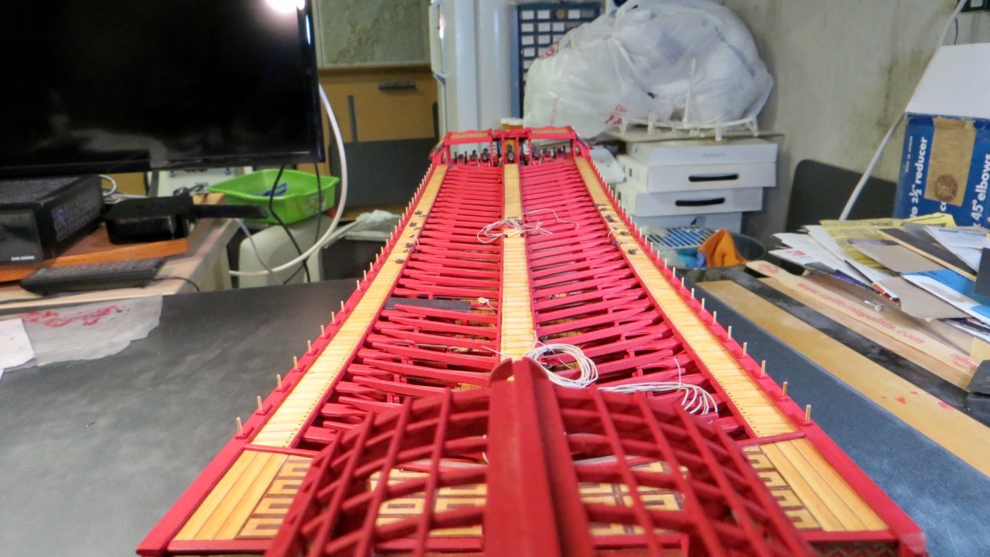
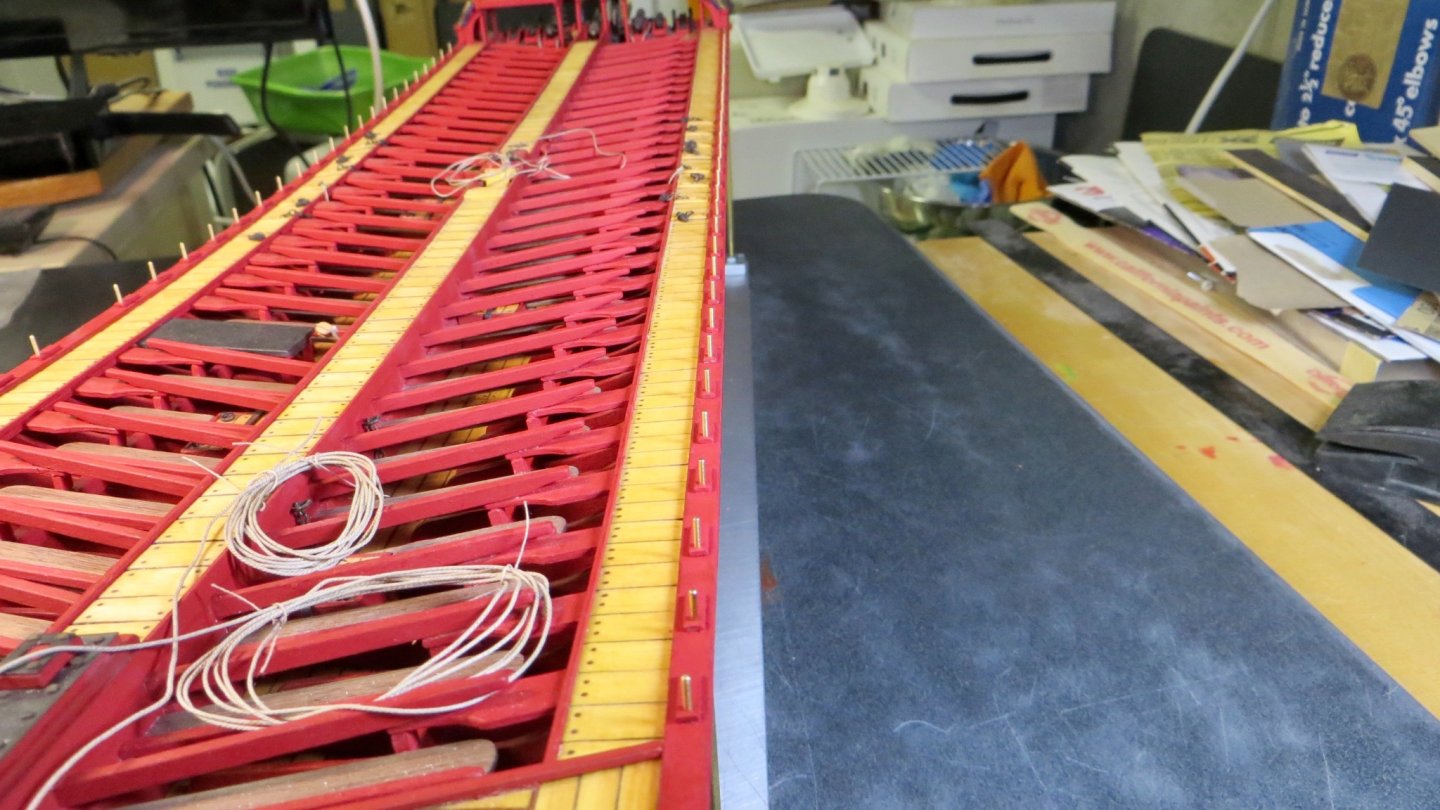
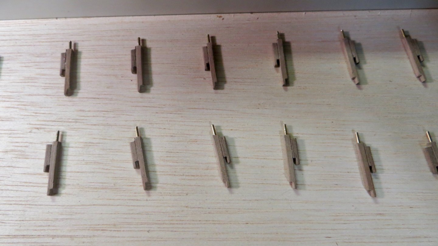
Hello, Small update. Slow, but steady progress! There are 11 swivel guns to be installed. Six on the starboard side and five on the port side. The mounts (posts) for the swivel guns are made. One of the swivel gun posts installed. 5 of the posts shown here. On the port side, where the cooking station will be, a swivel gun is omitted, thus 5 on the port side. In between all the railing posts and gun posts, there are 1mm x 2mm filler trim pieces installed. Work has begun on the davits for the launch boat. I will be modifying the davits to look a little bit more like those shown on the wonderful "La Fleur de Lis" plan by Gerard Delacroix. Photos to follow soon. Thanks for checking in! Frank


- 510 replies
-
- 10
-
-
- reale de france
- corel
- (and 1 more)
-
Beautiful work Mark! What does the piece of furniture fwd of the wheel represent? I ask because I notice the hole on top. Is something to go on top? Frank
-
I meant to say Proxxon Lathe in the post above. Damn auto-correct! Frank
- 510 replies
-
- 1
-
-
- reale de france
- corel
- (and 1 more)
-
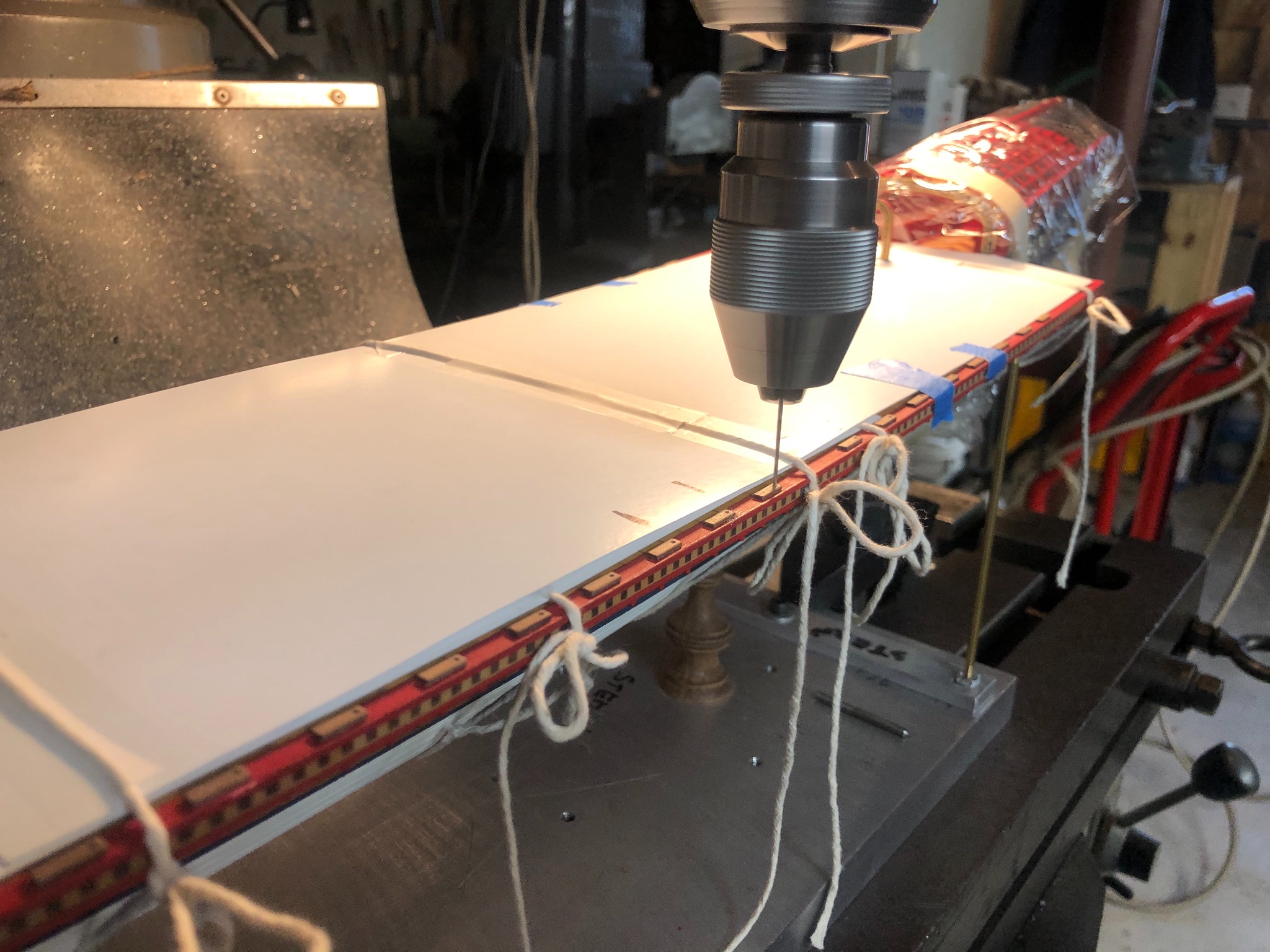
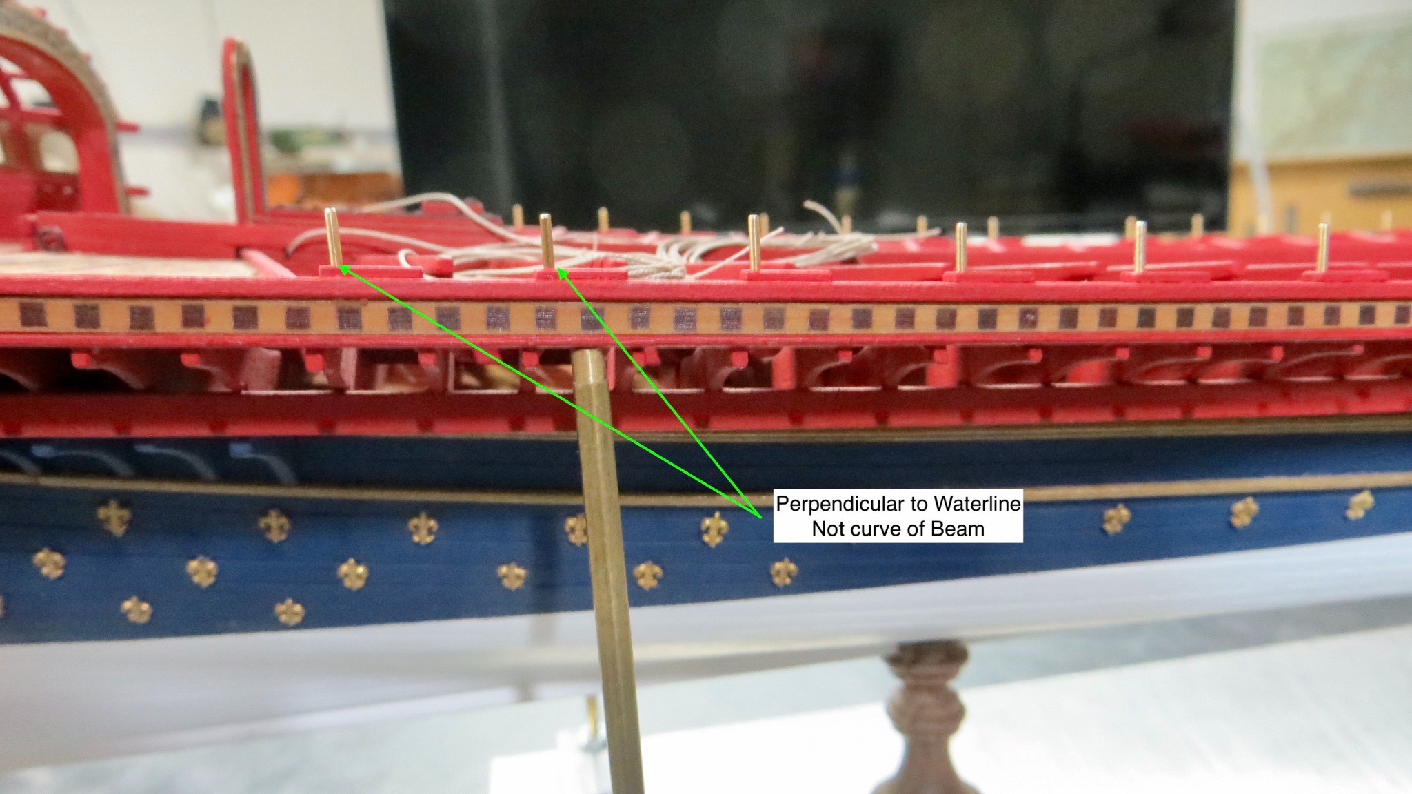
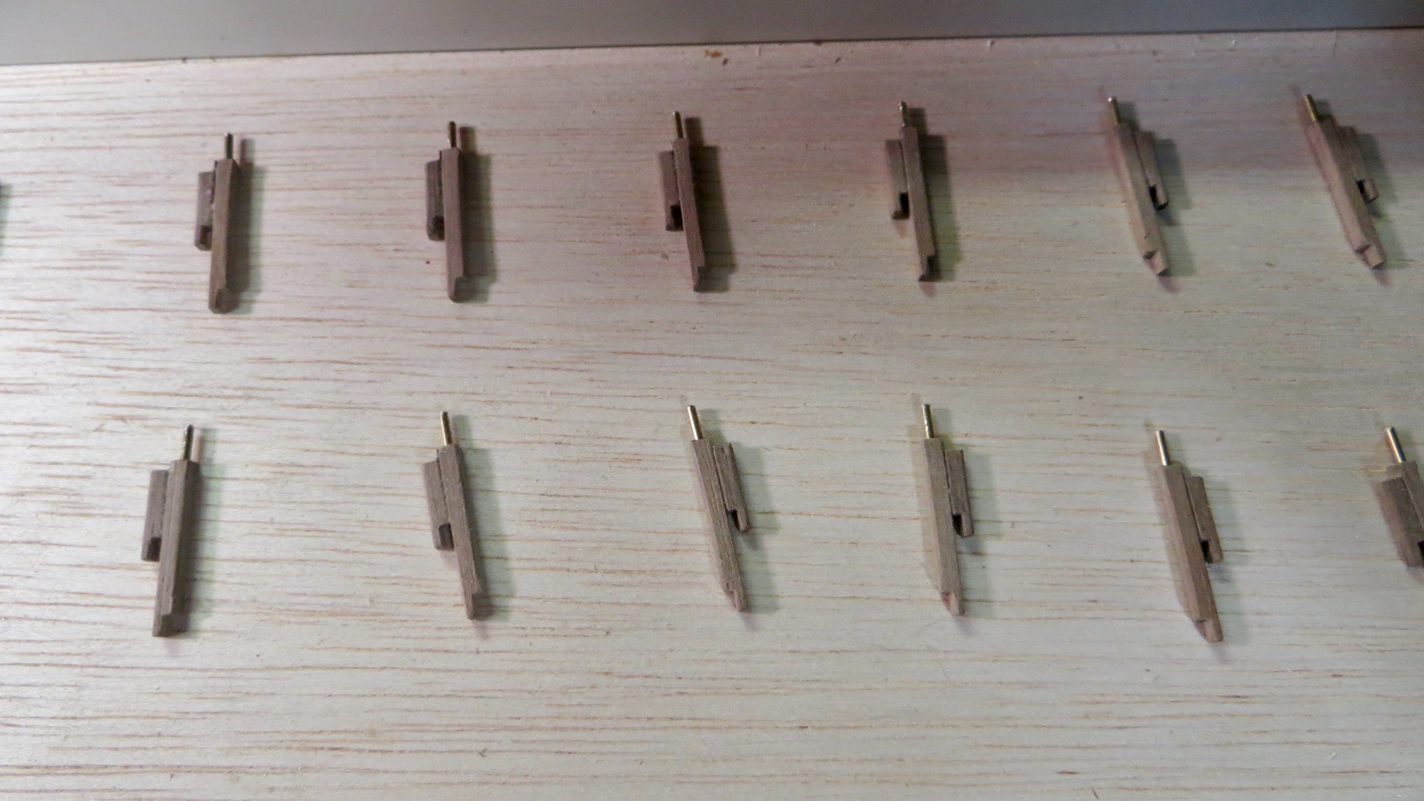
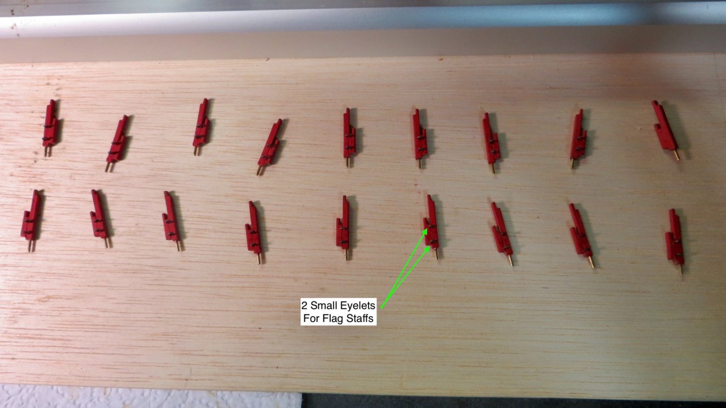
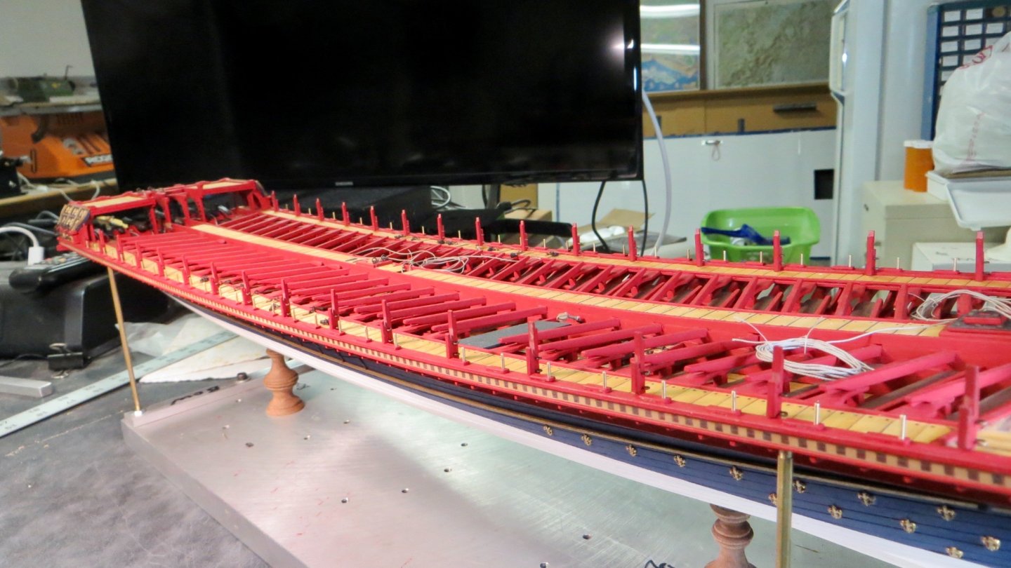
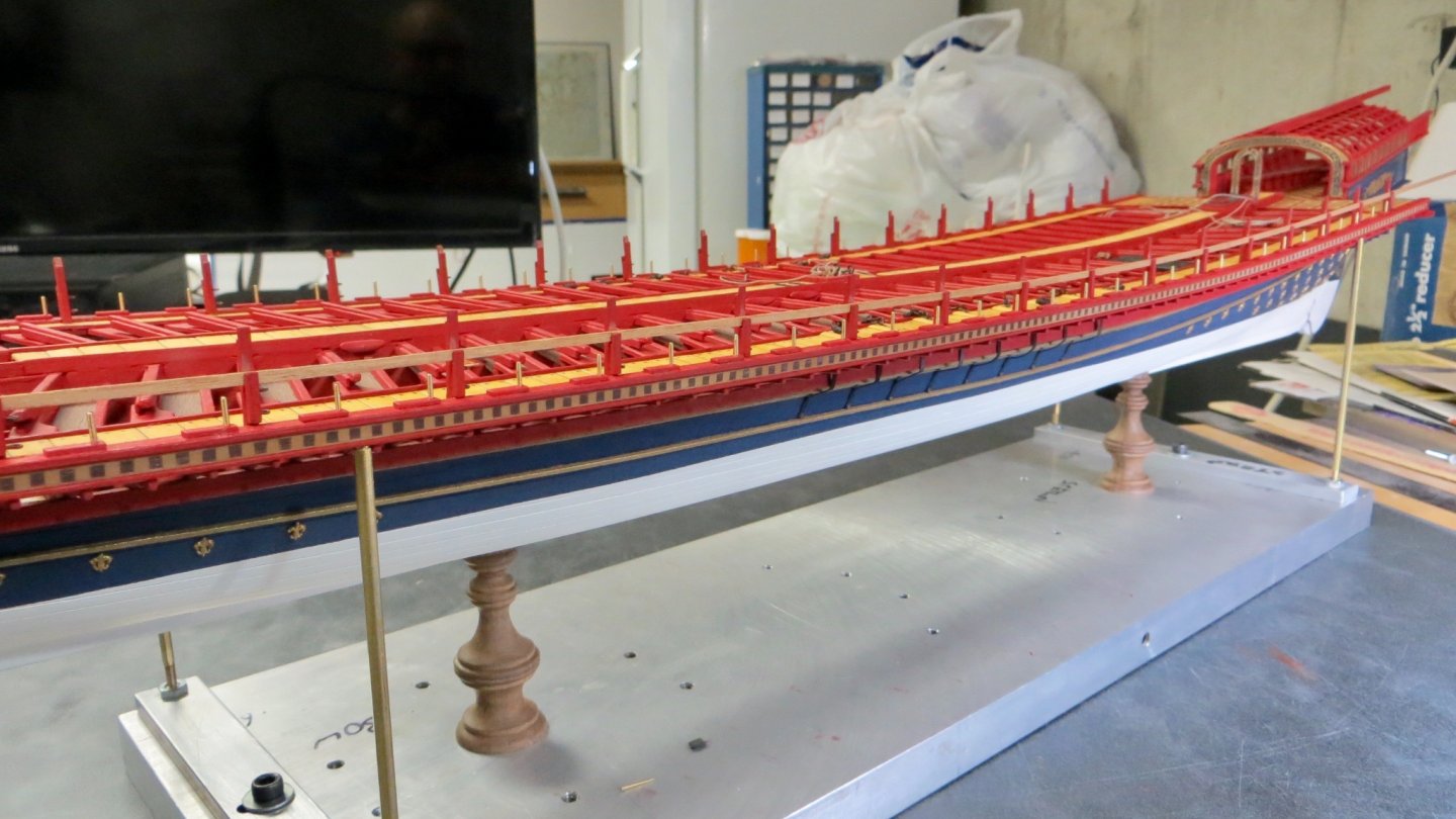
Hello, I was finally able to make it to my friend's house to borrow his large Bridgeport milling /drilling machine. With his guidance, I finished drilling the holes for the Thore-pins perpendicular to the waterline or table. The drill depth went about halfway into the main beam. Thore-Pins installed. 30 on the starboard side and 29 on the port side. Thore-Pins at 90 degrees from the waterline Next step was to start work on the railing stanchions. Since the stanchions are square (4-sided) I purchased a 4 jaw chuck for the Proton lathe. It worked nicely for drilling pin holes to support the stanchions on the deck. Upper and Lower Stanchions Attached with pins Each Stanchion will have a flag pole attached to the aft side. I added 2 small eyelets to support the flag staffs (which I will add later) Railing Stanchions fastened to the deck. Similar to the Thore-pins, the stanchions are perpendicular to the waterline, not the curve of the beam of deck. One of the hazards of working off of two different plans (Corel and Fleur di Lis) is positioning of details might have to be altered. Because I used the Fleur di Lis plan and raised the deck pieces, where the chain for the shrouds come thru the deck, I had to slightly shift where the Corel plan says the stanchions should be. Lower railing trial fitted (will be installed later). Final touchup on on red paint will be done after I finish the swivel gun mounts. Also just realized that the eyelets will have to be removed on 3 of the stanchions on the starboard side. There are no flag poles where the long boat davits will be located. Next steps will be making the swivel gun mounts and working boat davits. Thanks for stopping b for a look! Frank


- 510 replies
-
- 10
-
-
- reale de france
- corel
- (and 1 more)
-
All those little details you are adding make for a very fine model! Congrats! Frank
-
Great! Thanks for assisting Clark. Appreciated!! Frank
- 510 replies
-
- 1
-
-
- reale de france
- corel
- (and 1 more)
-
Hello Ogun, I hope all is well. Yes, I have the instructions and parts list. Give me a day or so to clean it up. (I penciled thru all the parts that I have installed in the parts list and crossed out all the directions I have completed). I will erase my pencil markings and get the instructions to you. The instructions come in English, French, and what I believe is German. You want the English instructions correct? Thanks, Frank
- 510 replies
-
- 1
-
-
- reale de france
- corel
- (and 1 more)
-
Looking nice Mark! How is the quality of the Carronades that come with the kit? From the photo, they look to be cast? I hope all is well, Frank
-
Nice touch with the use of different woods. You’re moving quickly!! Frank
- 112 replies
-
- 1
-
-
- corel
- reale de france
- (and 1 more)
-
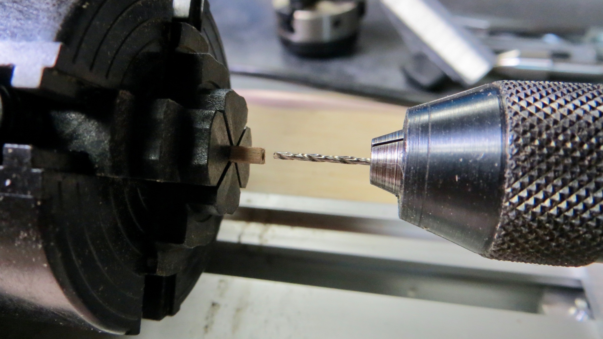
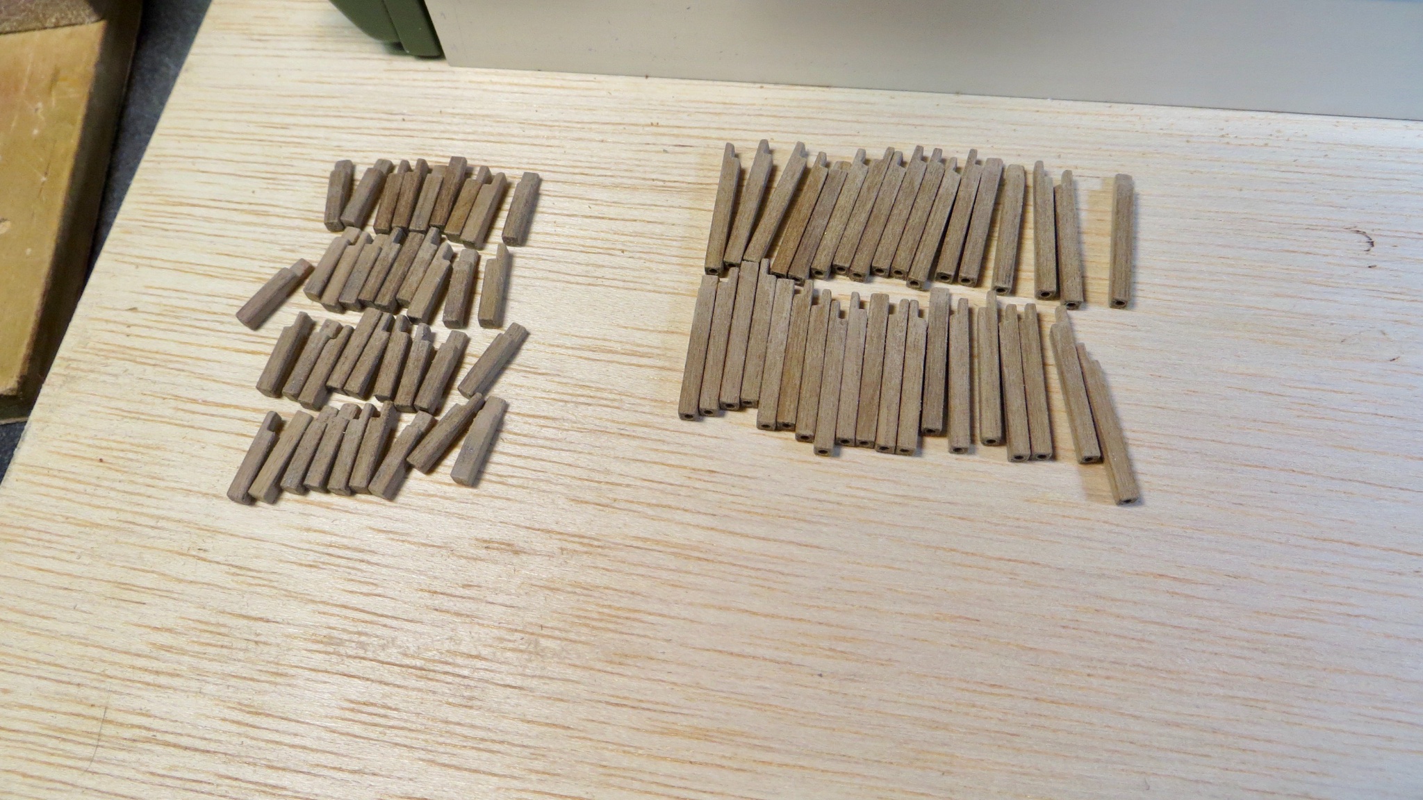
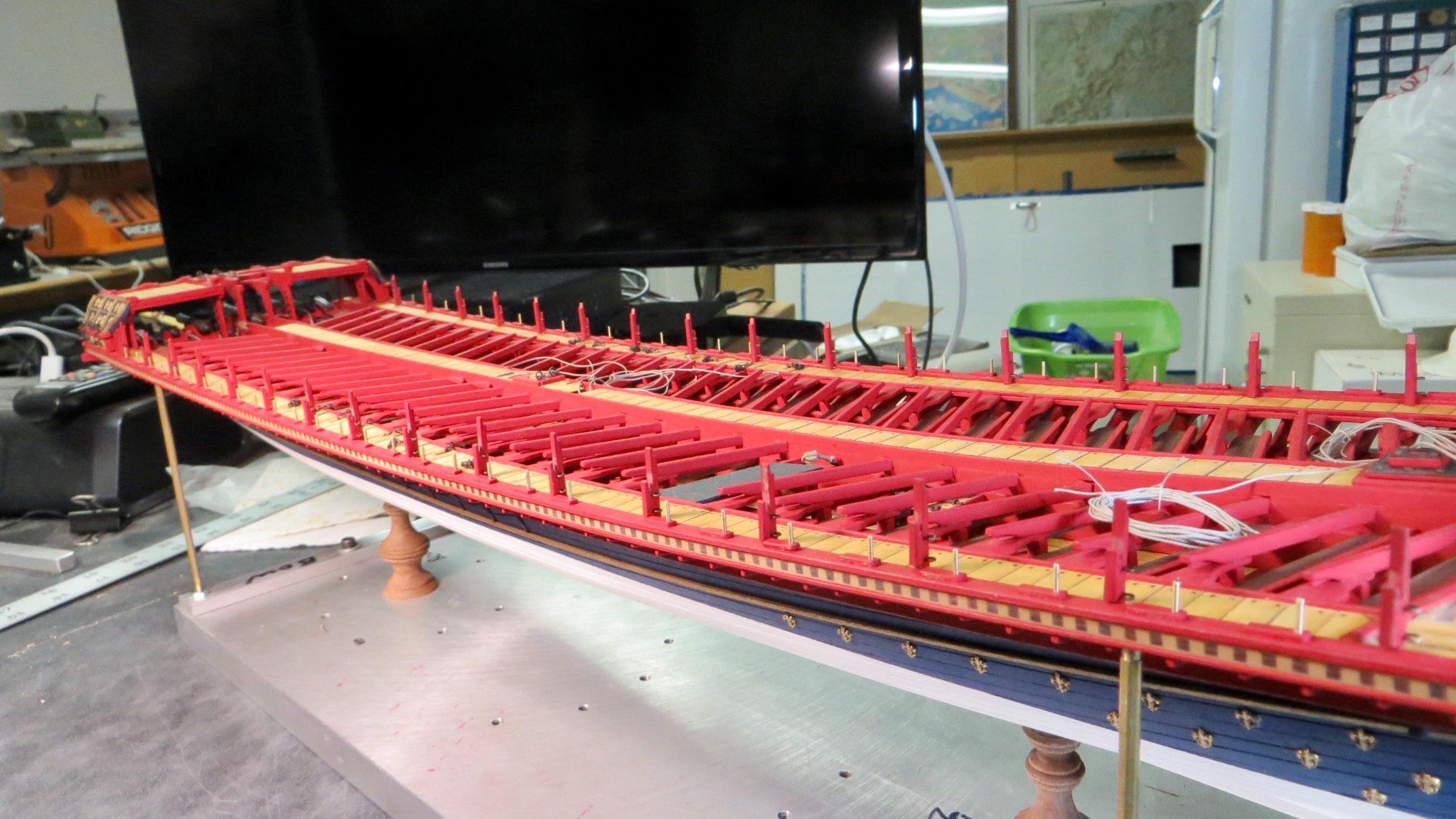
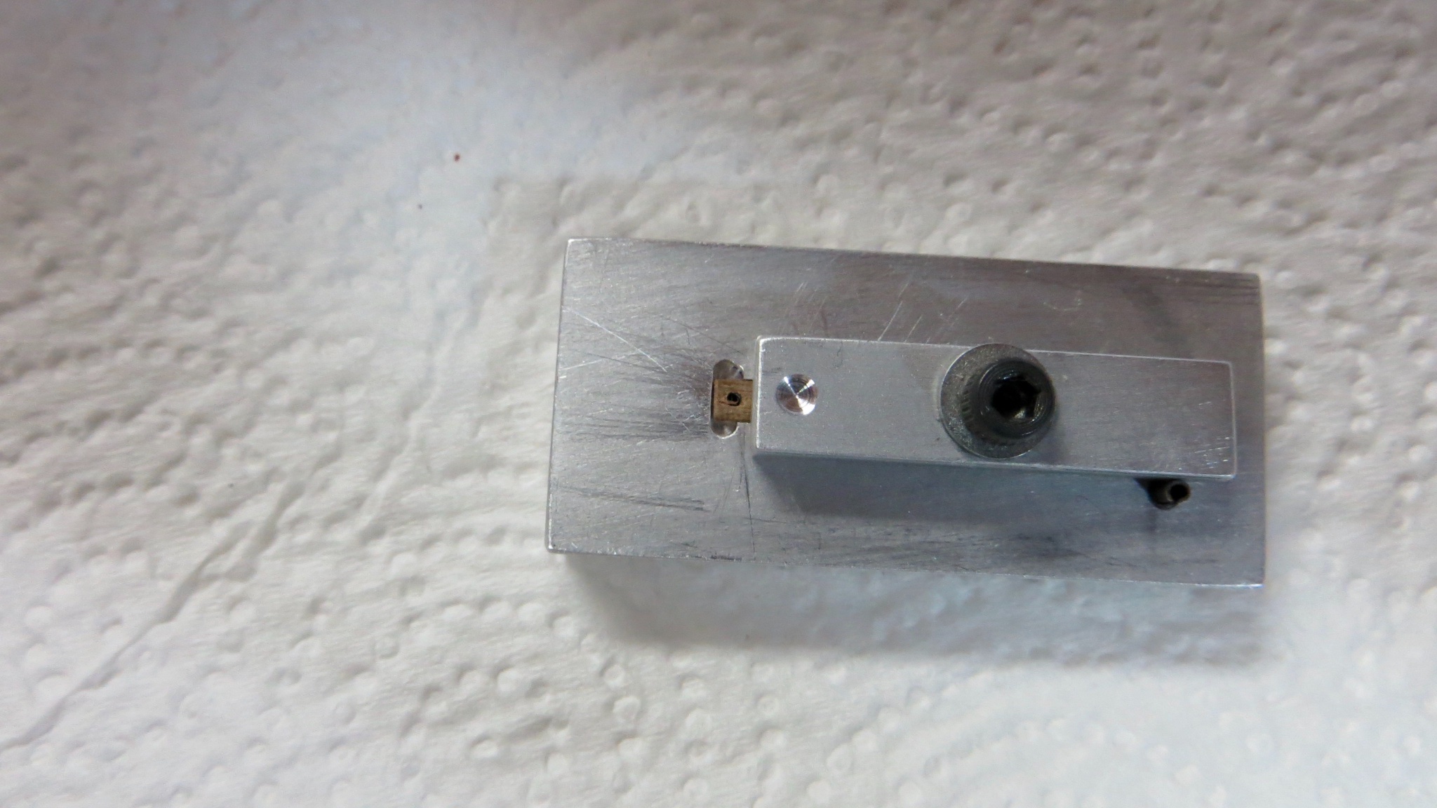
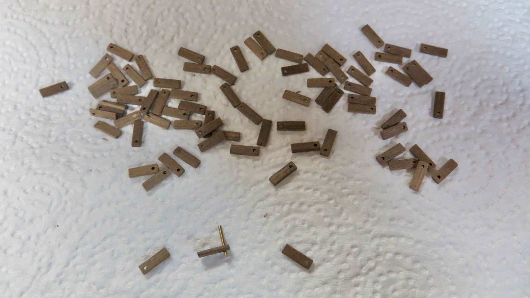
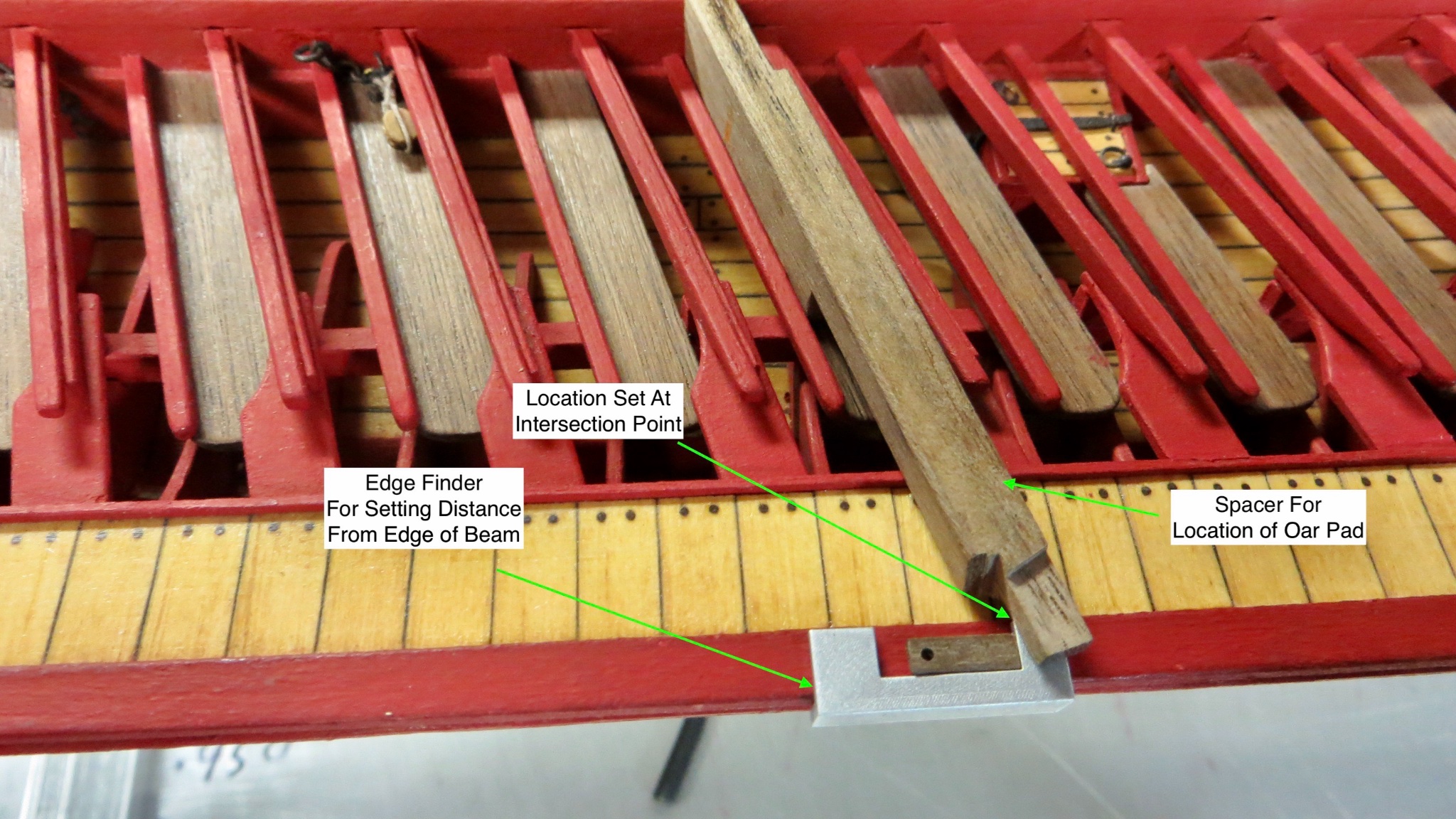
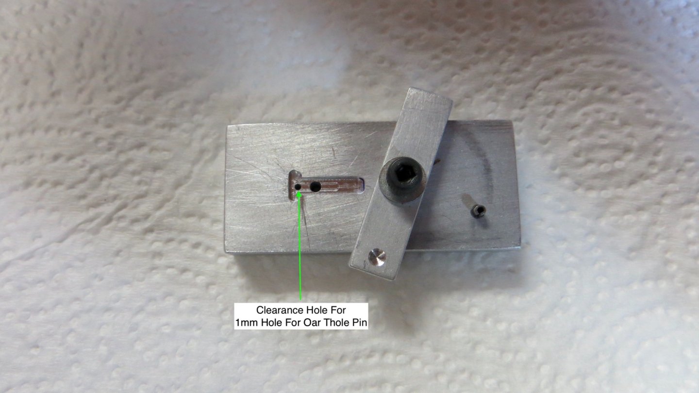
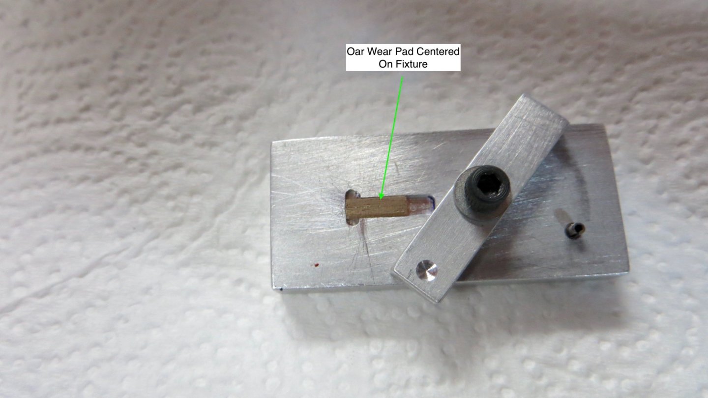
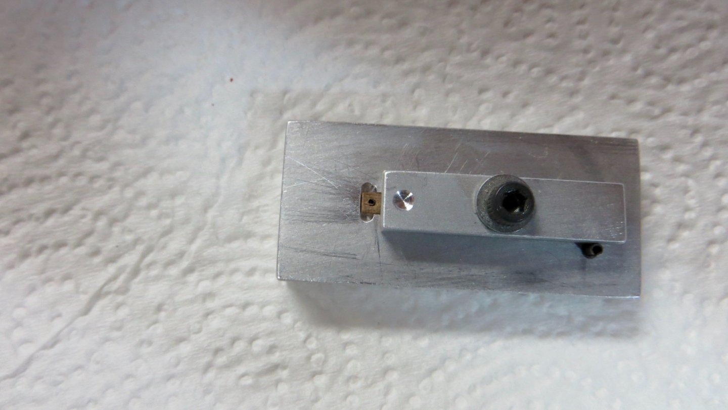
Hello, Small update: My next step is to make the oar pads and drill for the 1 mm pin that makes, what the Corel plan calls, the thore-pin. There are 59 of these. The plan calls for the thore-pin to sit right behind the oar pad, but I modified this a little. I made the oar pad a little longer and will incorporate the pin into the pad. The reason I did this is so a starter hole could be drilled onto the pad. Then when the pad is attached to the beam, the final drilling into the beam can be guided by the starter hole in the pad. (Yikes, I hope this makes some sense!) The reason for all this is that the pins need to sit perpendicular to the waterline and NOT perpendicular to the curve of the beam. (At least this is what the Corel plan calls for). Probably over-kill, but I took the time to have a small fixture made (helped by my friend with his equipment). This fixture will hold the oar pad for the drilling of the 1 mm hole Oar pad located on fixture. Thore-pin hole (1 mm) drilled thru on center of oar pad All oar pads drilled and ready to attach to the beam. In order to get the positioning correct on the side beams, a couple of simple fixtures were made. The first metal fixture sets the correct distance of the oar pad from the edge of the outer beam. The second wood made fixture sets the position of the oar pad along the length of the beam relative to the rower benches. I made it so the point where they intersect is the correct position as shown in the photo. Oar pads installed on the starboard beam. After I finish installing the pads on the port side beam, I will bring the model to my friends house, where I will set it on his large Bridgeport mill / drill machine. Using the existing holes on the pads as a guide, the 1 mm hole will be drilled perpendicular to the waterline into the beam and the thore-pins installed. Then the pads will be painted the ship's red color. Probably over-thinking things, but having fun! Thanks to all who have stopped by for a look! Frank


- 510 replies
-
- 13
-
-
- reale de france
- corel
- (and 1 more)
-
Nice job Michael! Good luck picking which plans to use for the rigging. Yikes! Lol! Frank
-
Hello Michael! Happy New Year! And thanks for stopping by for a look (and kind words) at my progress. Appreciated! Best, Frank
-
Hi Clark, Thanks for stopping by. Happy New Year. The only reason I added the Rudder chain is because I saw it on The excellent Fleur De Lis plans by G Delacroix. I am assuming his plans are more accurate than the Corel plans!!! As far as the figurines, I do have enough to add to the remaining areas. Some of them, as you know, are in bad shape and not fully cast. But I believe I have enough good ones for the remaining areas! Thanks, Frank
- 510 replies
-
- 3
-
-
- reale de france
- corel
- (and 1 more)
-
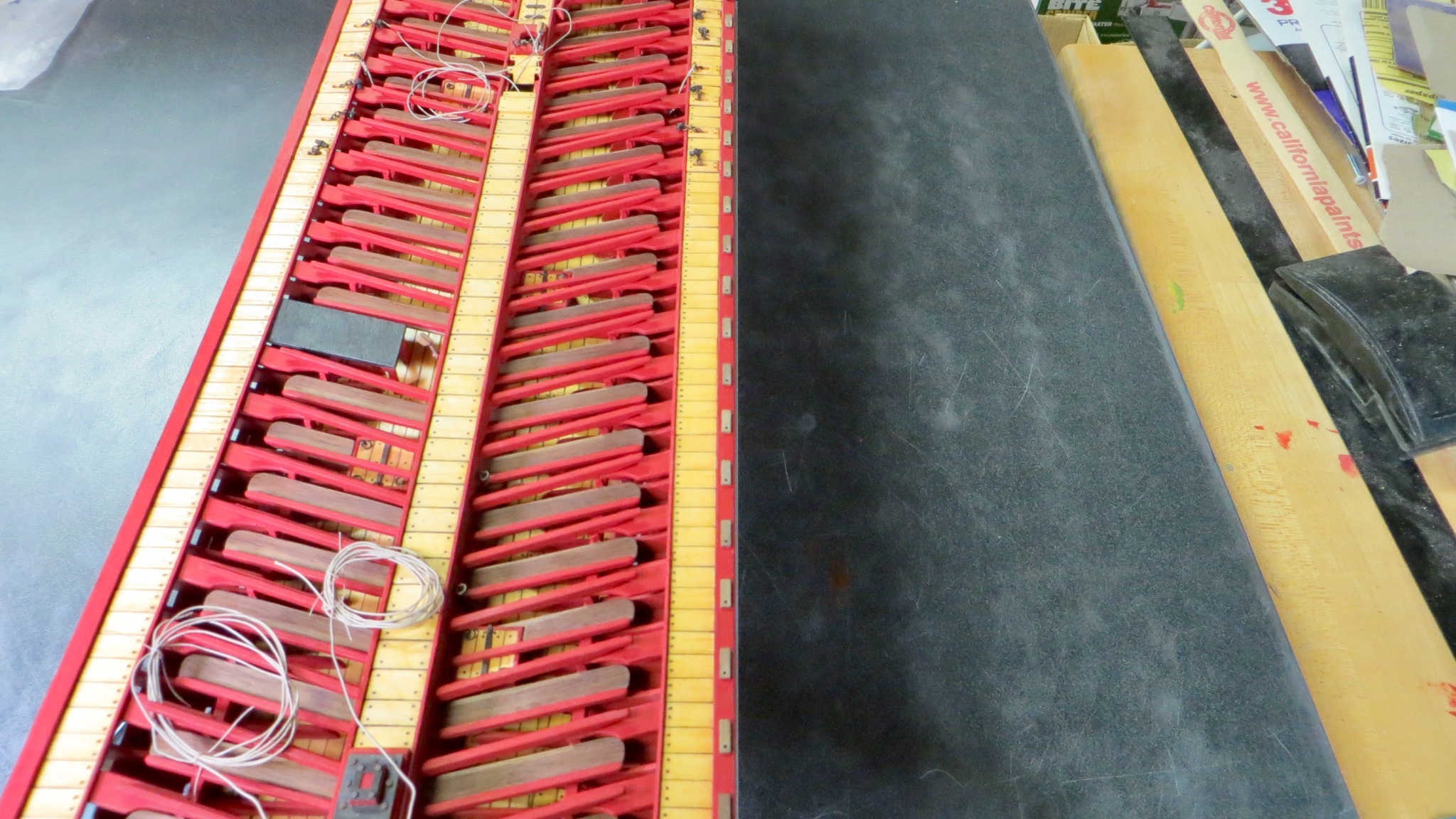
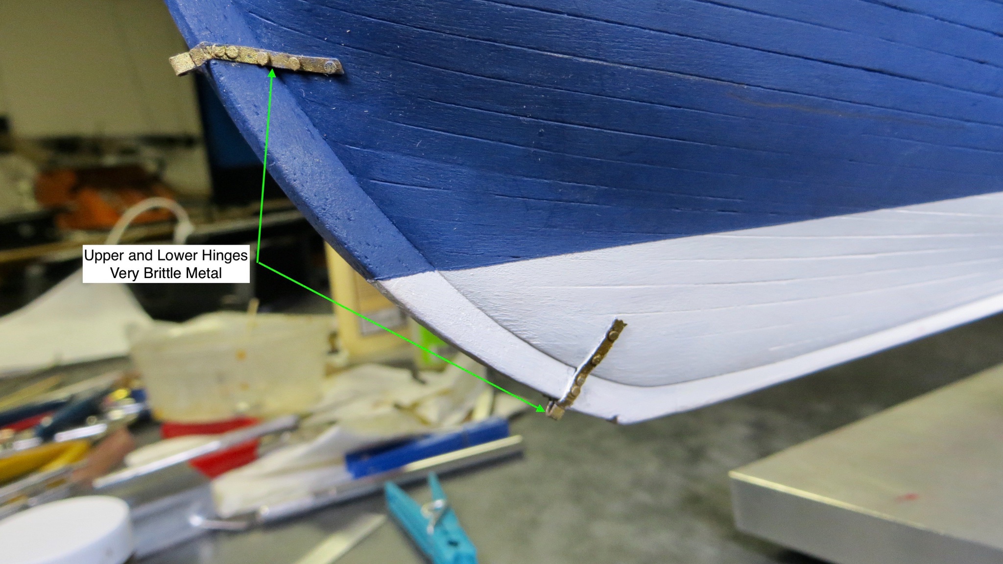
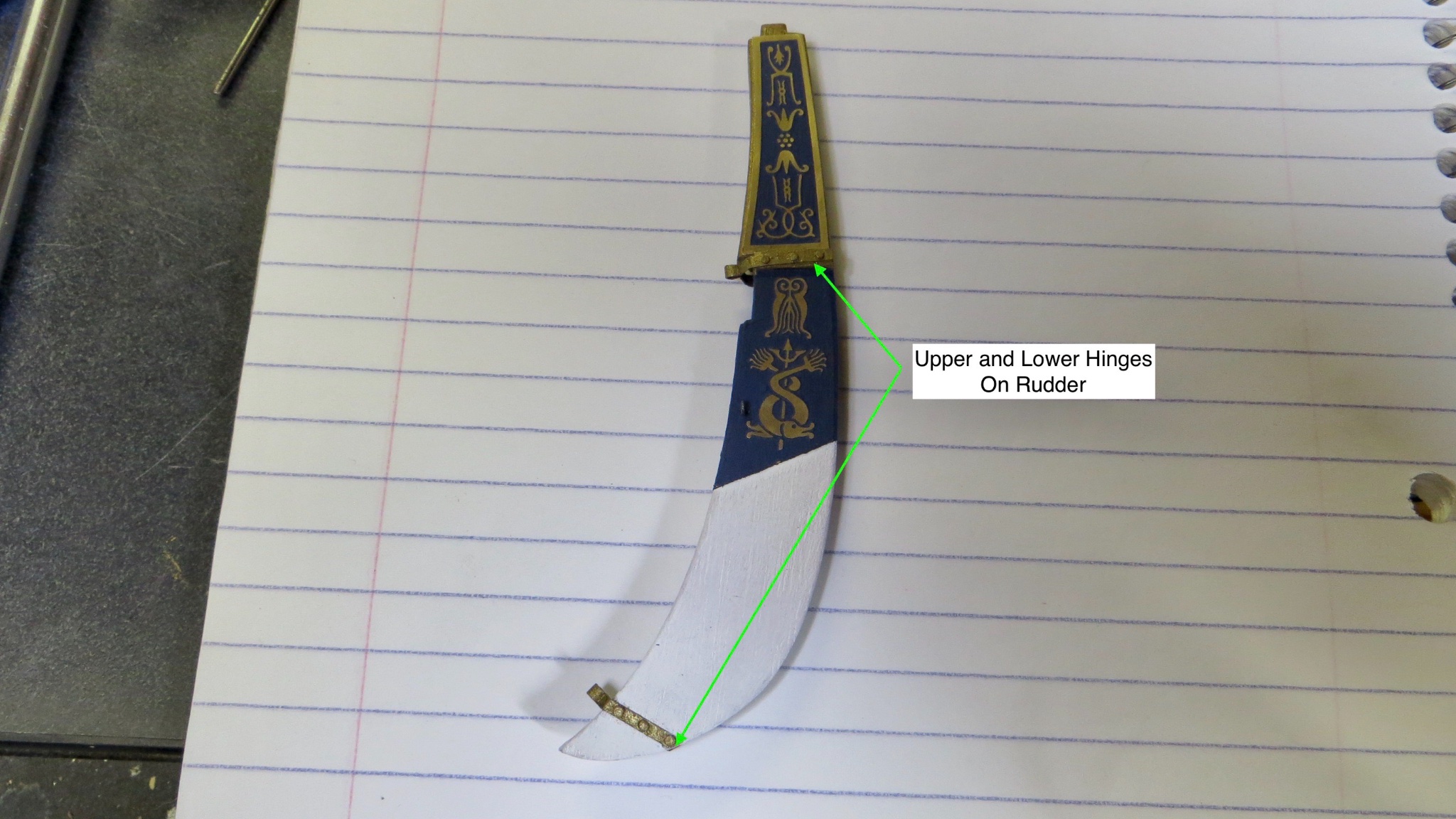
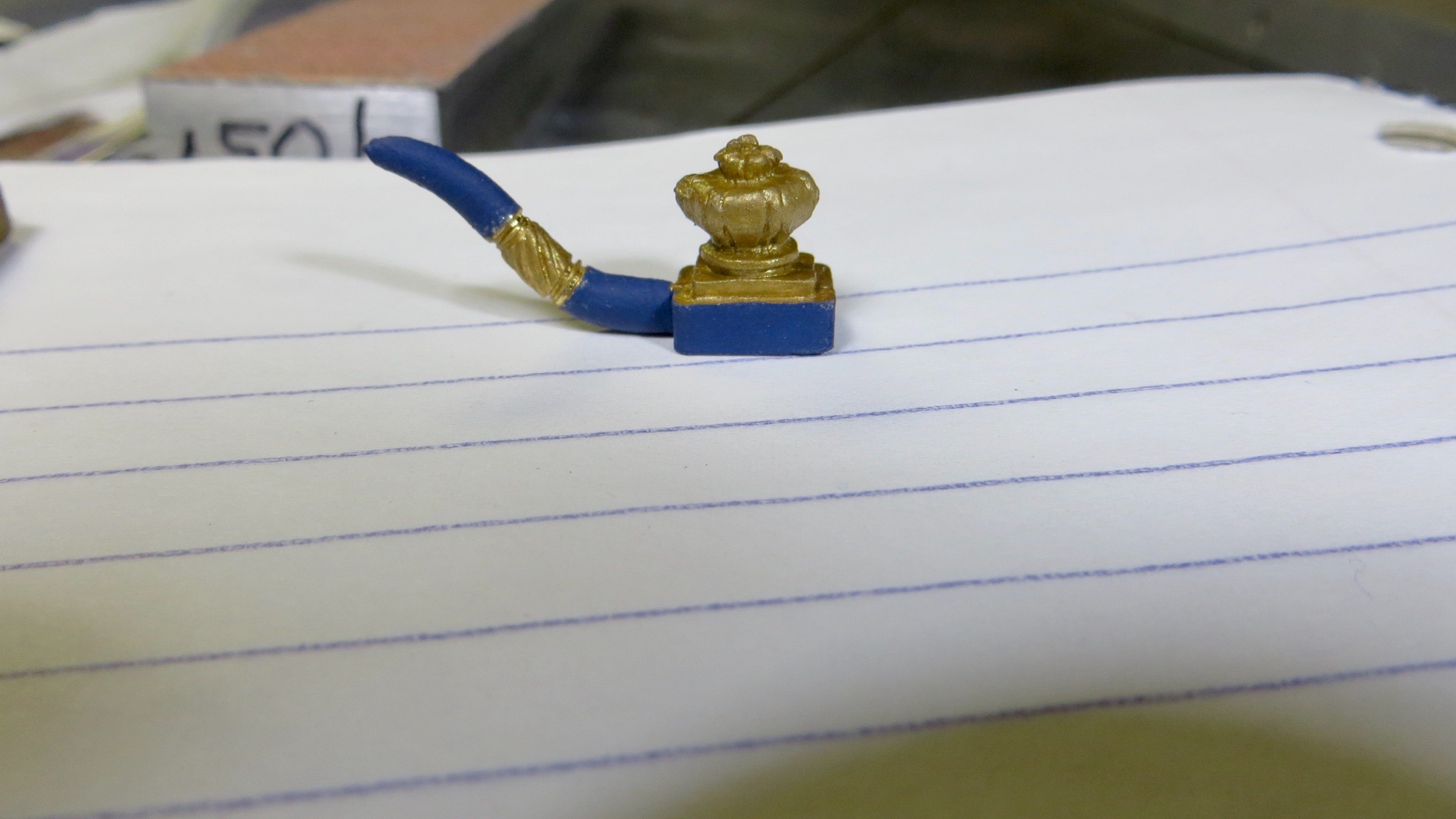
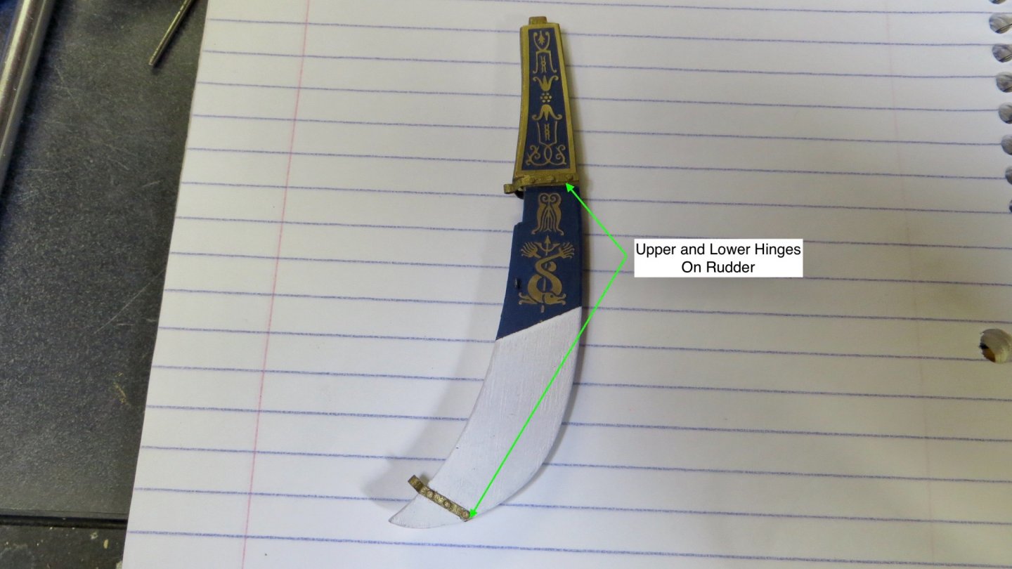
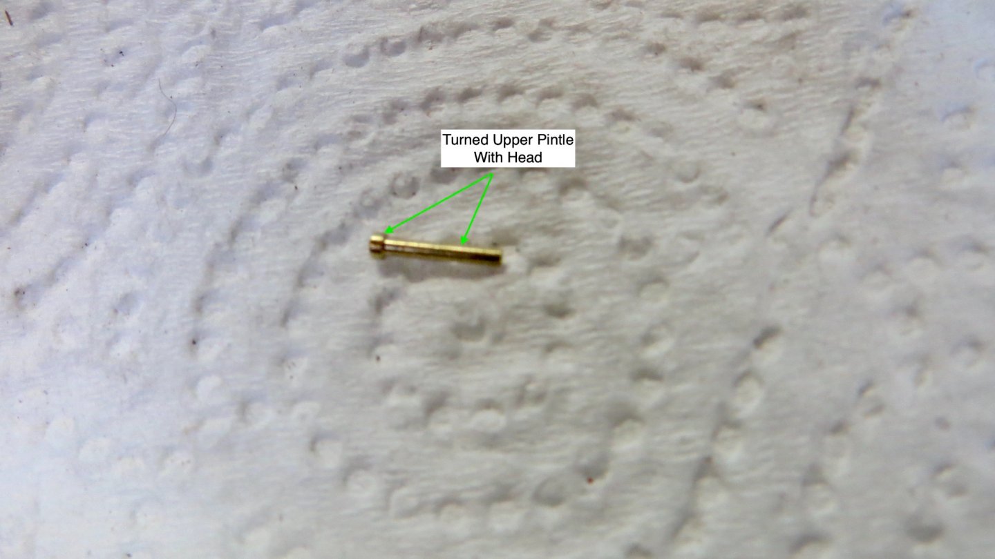
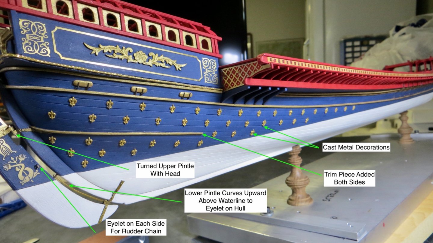
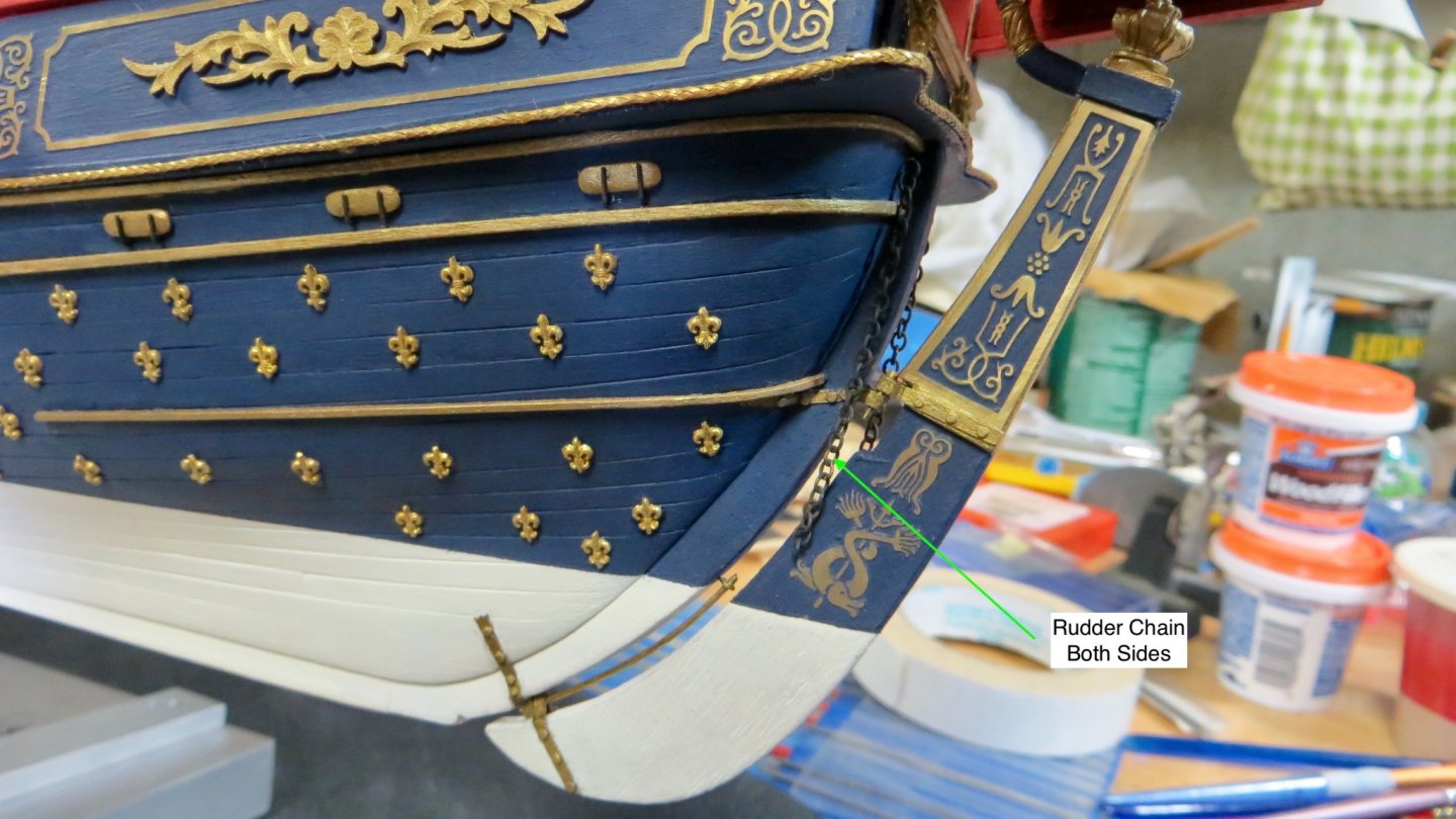
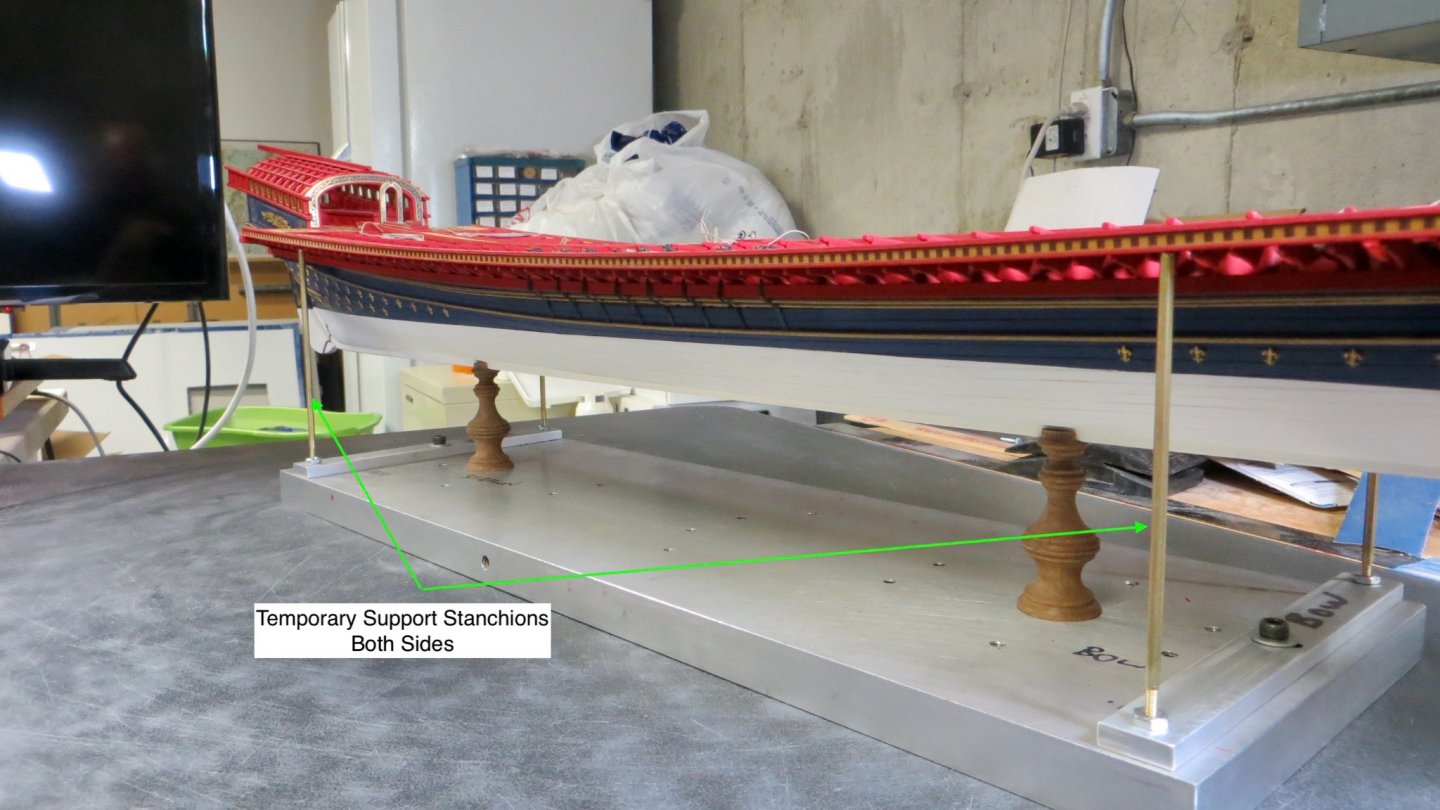
Back working on the model after some time off! Continued working on the rudder assembly. The Corel kit supplies the modeler with 2 sets of upper and lower hinges for the hull and rudder. Thank goodness they did. The hinges are very brittle and if bent or shaped too aggressively, they break off. I had to learn the hard way! Hinges attached to the hull of the model. Hinges attached to the Rudder Ornamental Cast Tiller painted and ready to install. Both the Corel plans and The Fleur De Lis plan show a short tiller going into the Royal area of the ship. I don't quite understand this. There must have been a tiller crew member manning the tiller in the royal sitting area. Also, as stated in Clark's log, the tiller seems very short. I'm thinking a lot of the steering must have been done by the oarsmen. The upper hinges are supposed to attach to each other with only a 1mm brass rod. The only thing keeping the rod from sliding thru would be glue. I wasn't happy with this, so I made up a brass pin with a top head on it for safety. The next photo shows many things: Before attaching the rudder, I added the many cast metal decorations. As told to me by a post on Clark's Reale log, the decorations were actually painted on the real ship. I filed off as much of the flashing as I could, then painted them the antique gold I have been using and attached to the model. Also add a lower trim strip piece just above the upper hinge. The lower pintle is interesting in that it extends from the lower hinge to above the water line. The Fleur De Lis plan seems to show the upper end tied to the hull. Since it was real tight in there, I attached a very small eyelet to the hull, and slid the curved rod into it. Not sure what the purpose of this long pintle is, but since it ends above the waterline, could this have allowed a crew member to disengage it from the lower hinge, if needed, without having to go underwater? Finally, an eyelet was added to each side of the rudder for the rudder chain. The Fleur De Lis plan shows 1 chain attached between the hull and rudder with a horseshoe type clamp. Since it was very tight in there, I modified it and added a chain to each side. Decorations added to the bow area. Port Side Decorations near stern Rudder chain added to both sides of Rudder The next step in the build, for me, is to start work on the topsides, drilling and installing 59 oar wear pads and 59 oar thore-pins. The thore-pins do not follow the curve of the deck, but are perpendicular to the water line. This will require me to bring the model to my friends shop and borrow his large Bridgeport drill / milling machine to drill the 59 holes perpendicular to the waterline. So in preparation for this I had some temporary supports made to sturdy up the ship and level the model. Thanks again for stopping by and visiting. Appreciated. Happy New Year! Frank


- 510 replies
-
- 15
-
-
- reale de france
- corel
- (and 1 more)
-
Thanks Michael! Just ordered the shapers! Frank
-
Beautiful work on the door and platform! Lots of detail! I'll have to order the micro shapers you showed in one of the photos!! Best, Frank
-
thanks for the information Clark! I will be working on the pins soon. Still working on the rudder assembly. (A real pain with the brittle parts) Frank
- 112 replies
-
- 1
-
-
- corel
- reale de france
- (and 1 more)
-
Hi Clark, Nice job on the Thole Pins. A couple of questions if you don't mind: 1. What height did you set the thole pins to? 2. As you know, the horizontal beam that the thole pin drills into has a long curve to it from the stern to the center. Did you place the thole Pins perpendicular to this beam or perpendicular to the water line? Thanks for the assistance, Frank
-
Hi Clark, Thinking ahead a little, since you are ahead of me. Do you think the real ship had all these ornaments on the hull? I am undecided as to whether adding them is overkill or not. Let me know your thoughts. Also, what glue did you use to attach them to the hull? Thanks for the help, Frank