HOLIDAY DONATION DRIVE - SUPPORT MSW - DO YOUR PART TO KEEP THIS GREAT FORUM GOING! (Only 13 donations so far - C'mon guys!)
×

fmodajr
-
Posts
868 -
Joined
-
Last visited
Content Type
Profiles
Forums
Gallery
Events
Everything posted by fmodajr
-
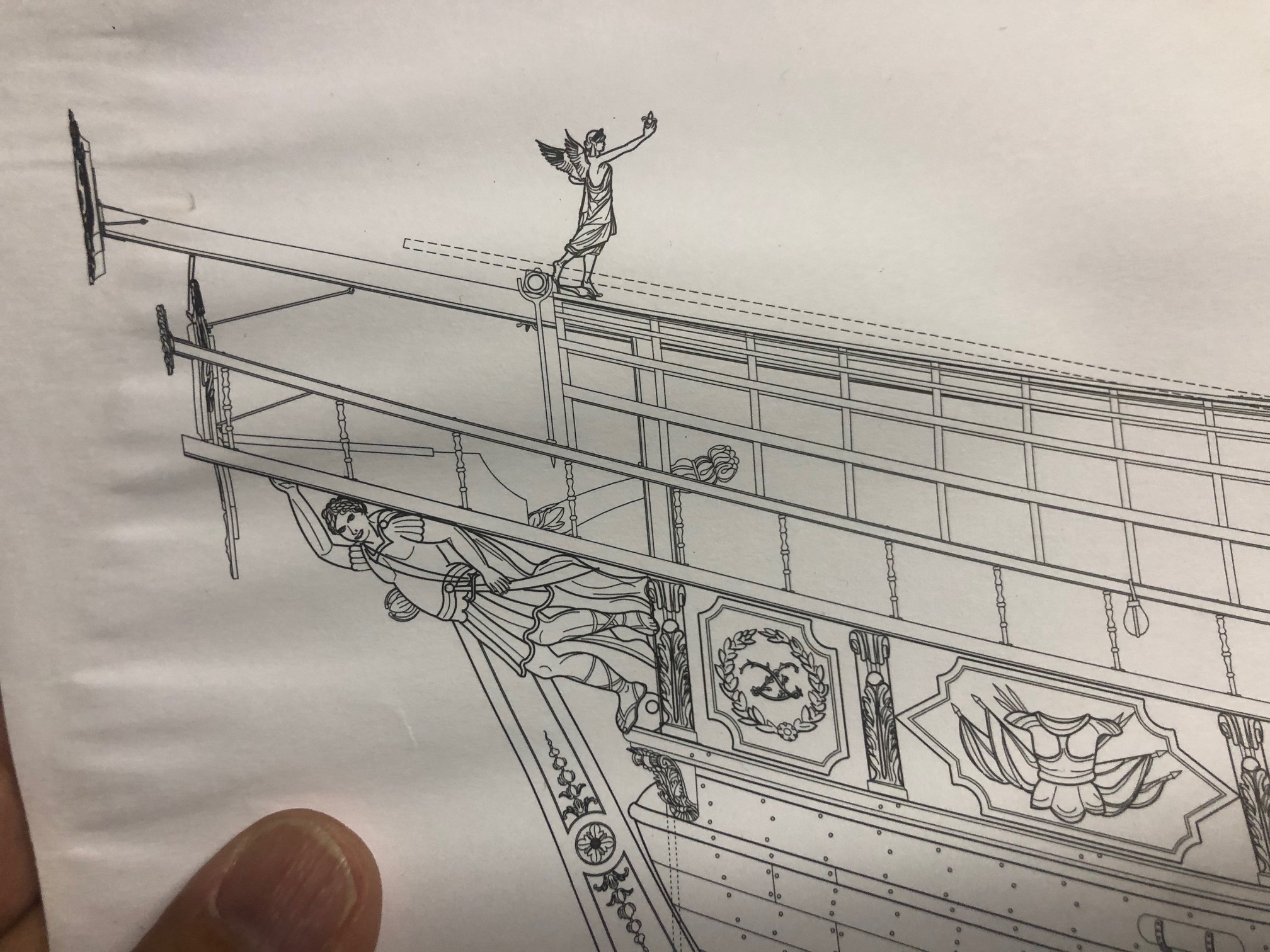
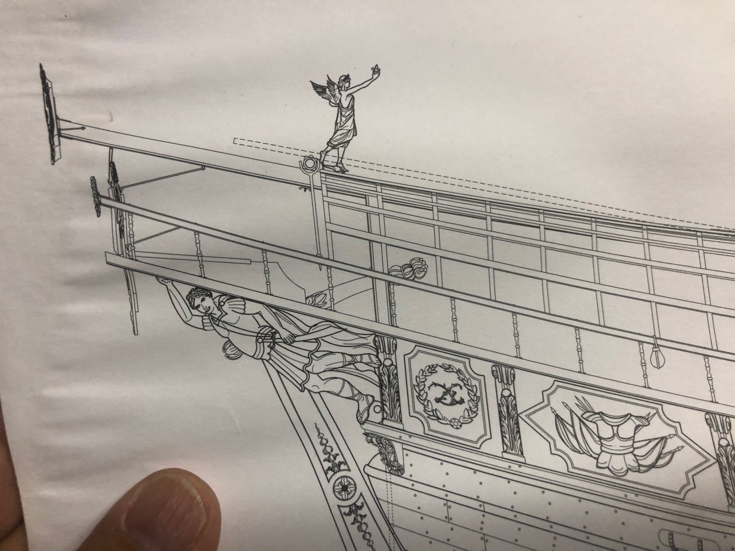
 Hi Clark, I am not home now, so I can't check my Fleur di Lis plans. Check out this link, I I think you will see that the oarlocks are correct facing the stern. The oarsmen are facing the stern. I hope this helps. Frank
- 510 replies
-
- 1
-

-
- reale de france
- corel
- (and 1 more)
-
Congrats on finishing the first planking layer! Frank
-
Clark, Nice job on the difficult bow deck planking. Yes, I agree. the Corel kit supplied catheads are horrible. I made mine from scratch also! Frank
- 112 replies
-
- 1
-
-
- corel
- reale de france
- (and 1 more)
-
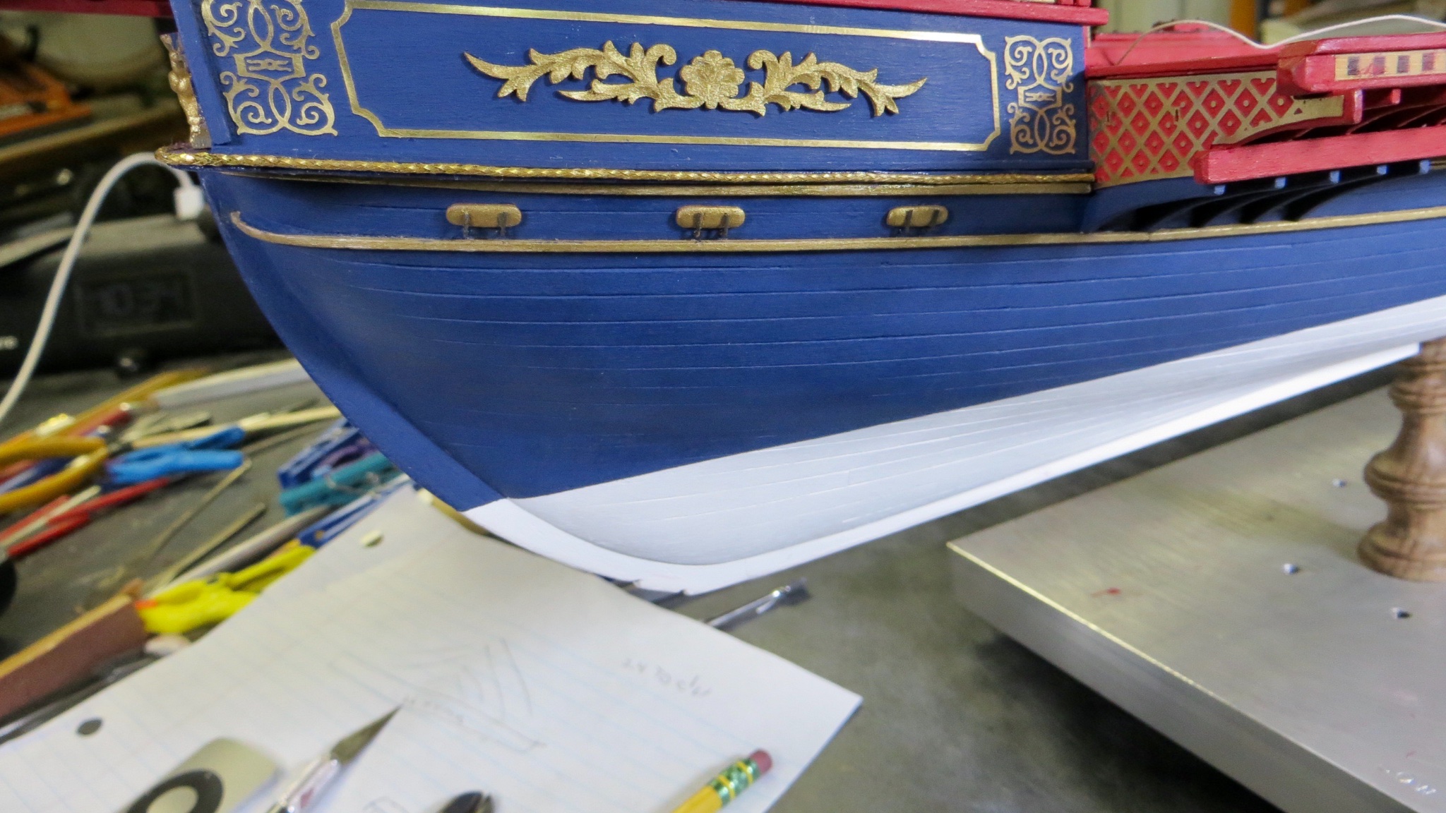
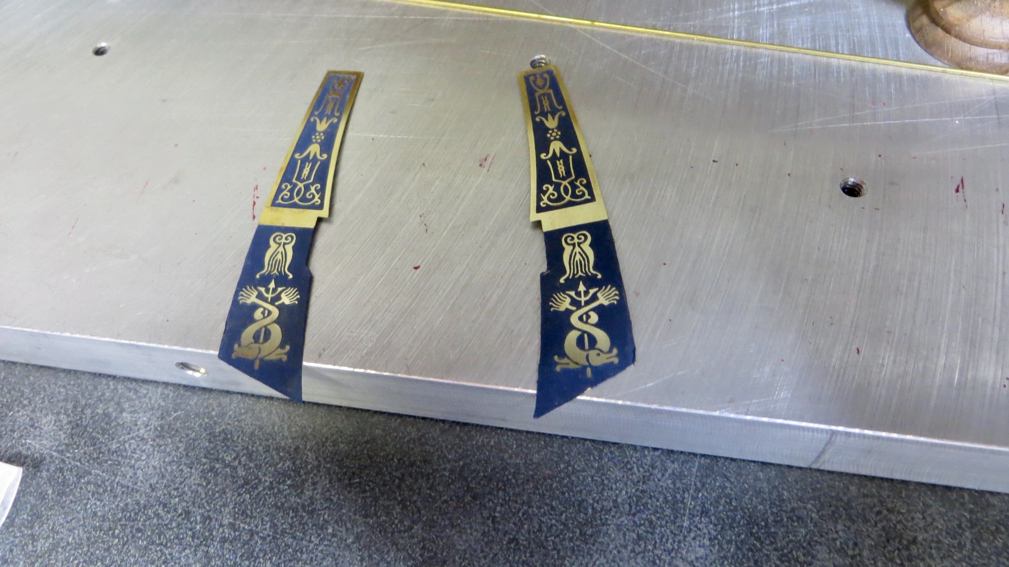
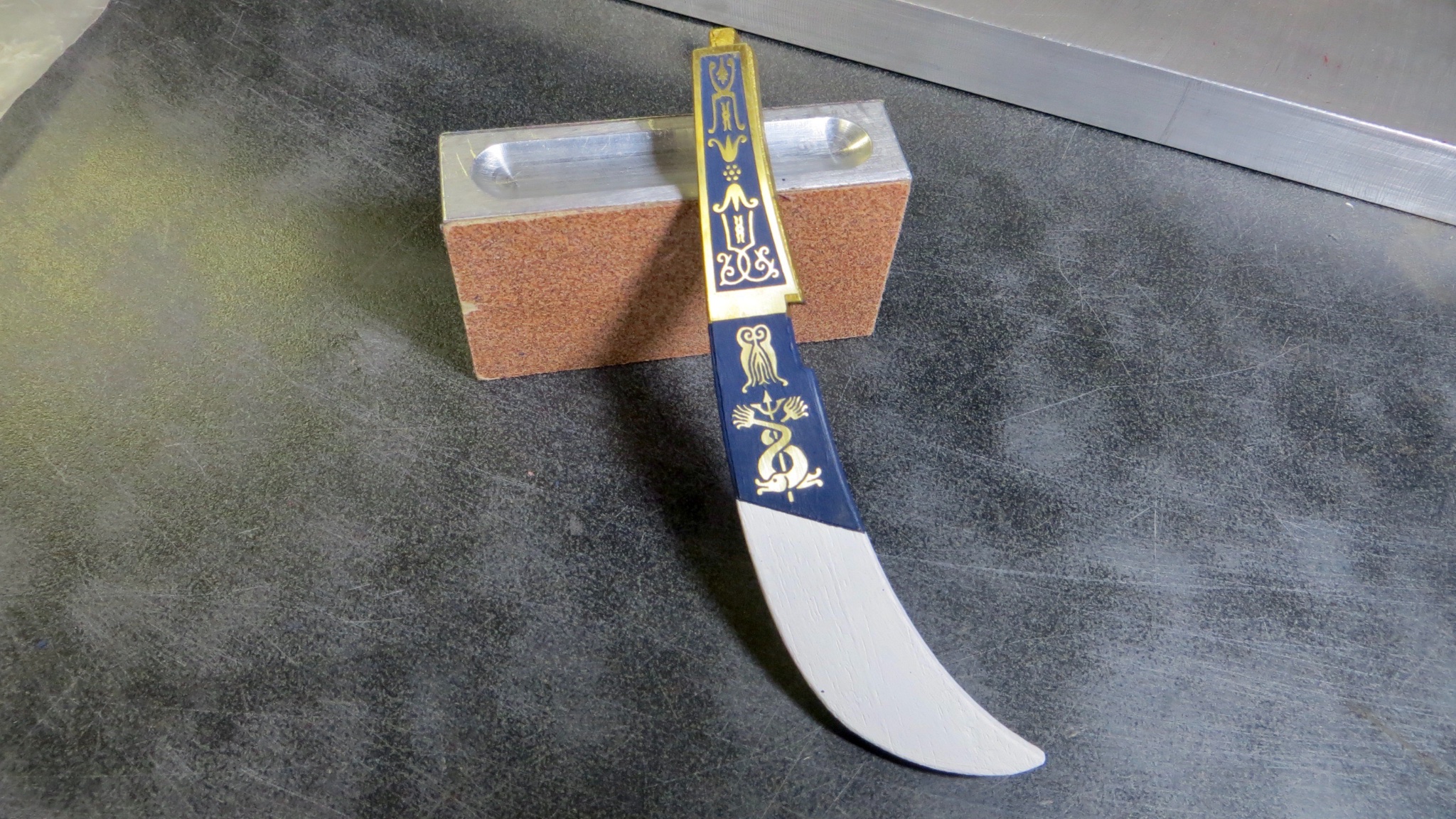
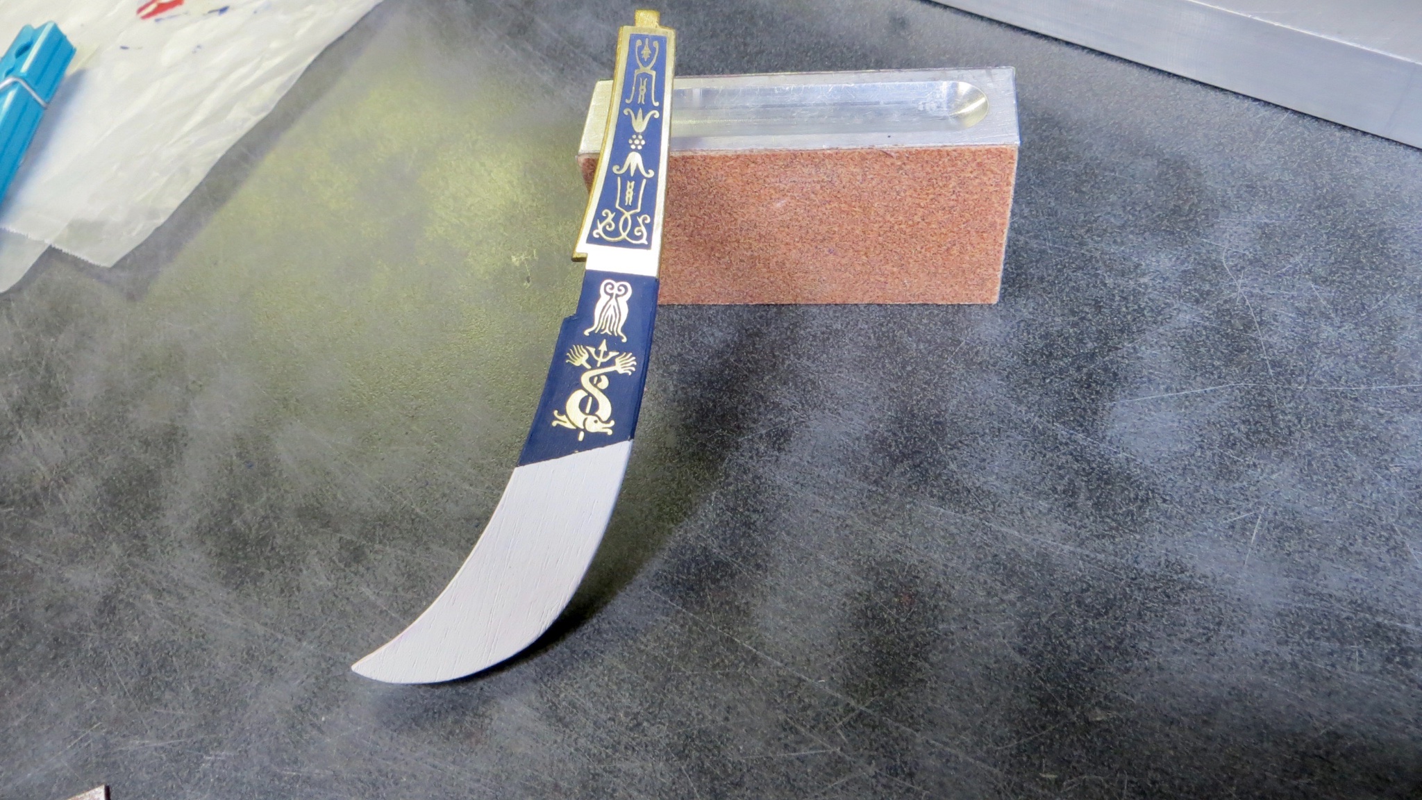
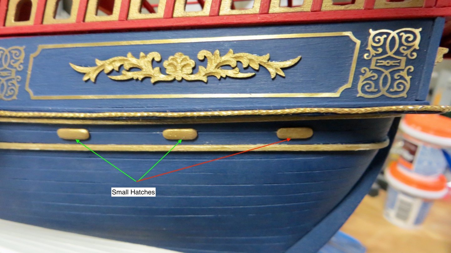
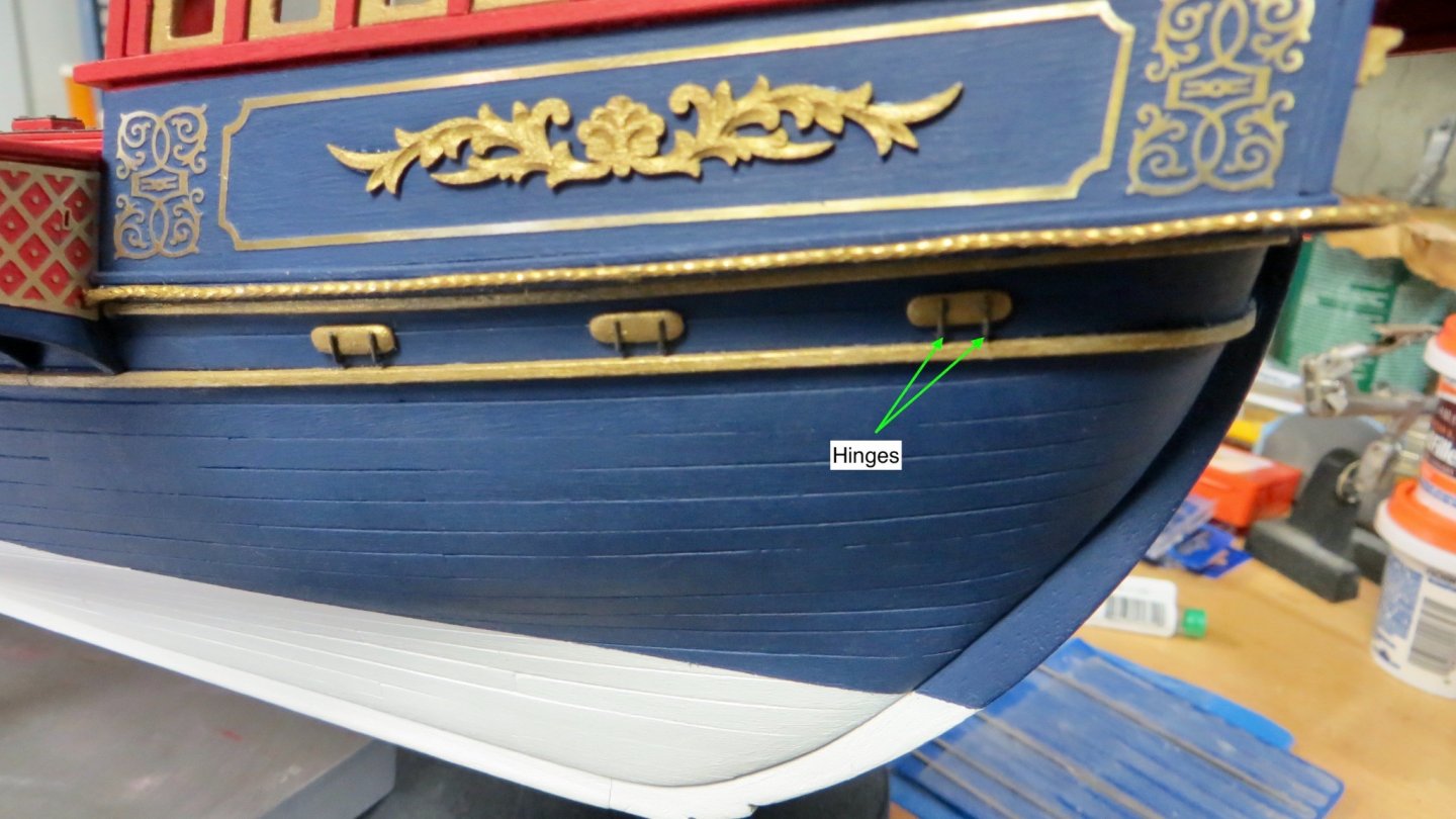
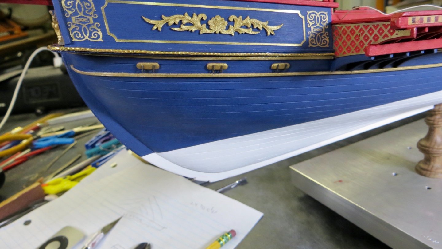
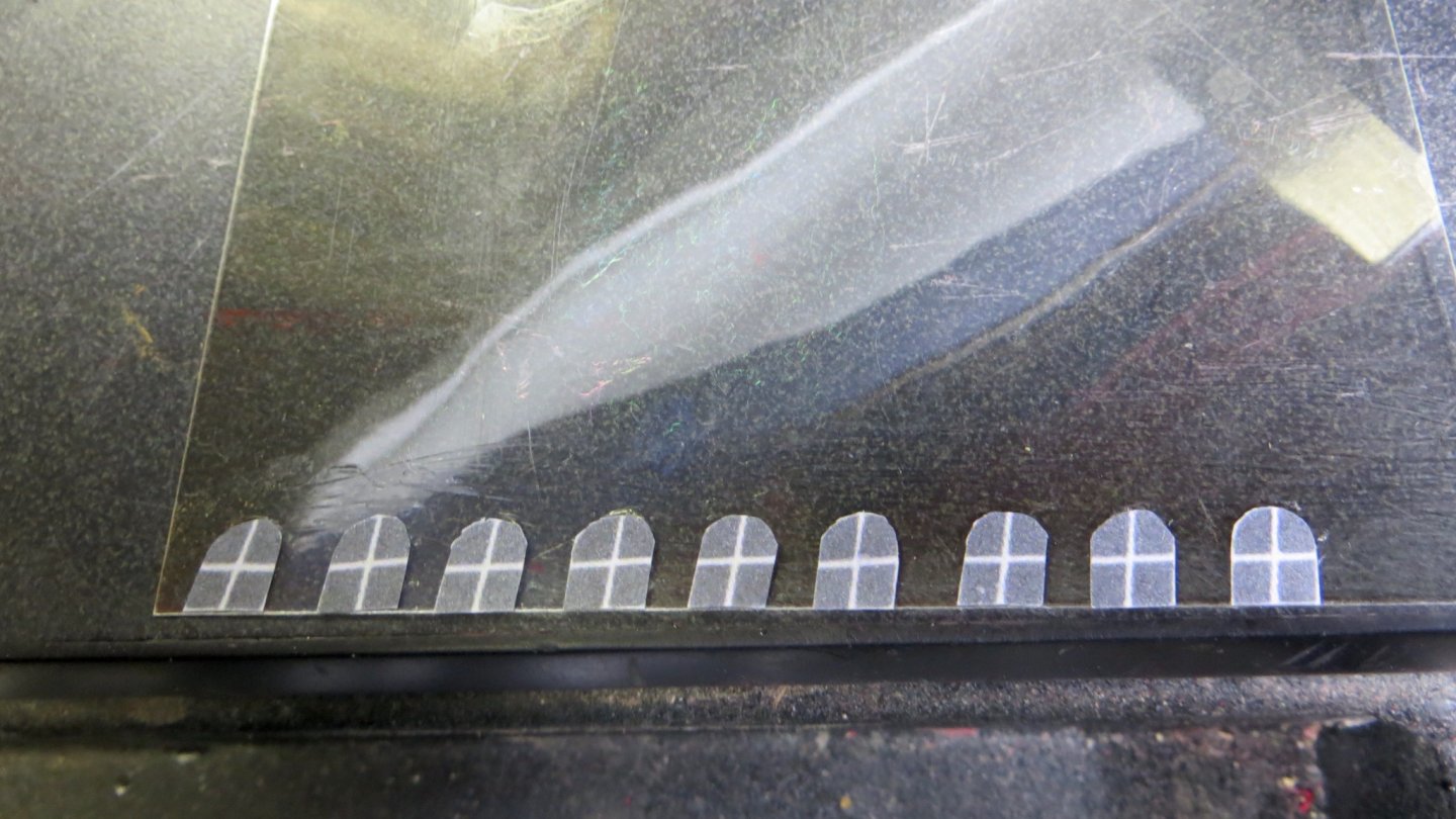
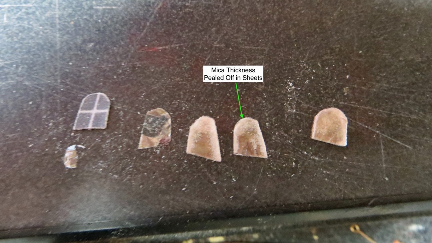
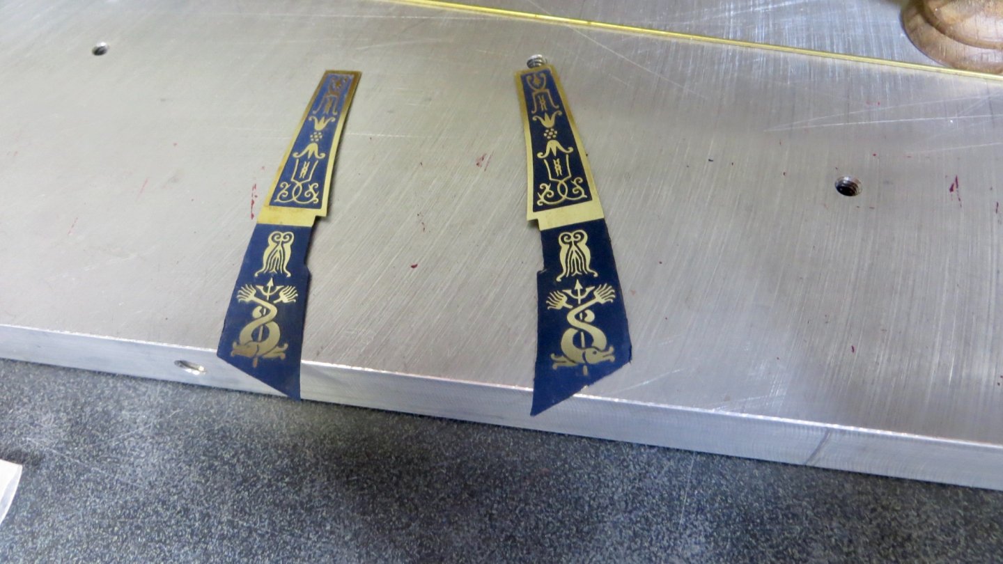
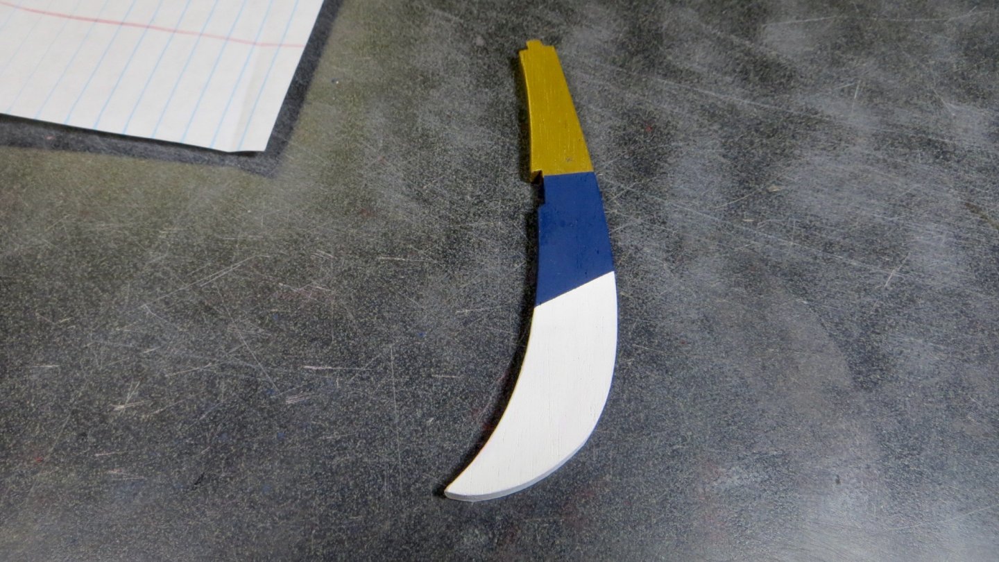
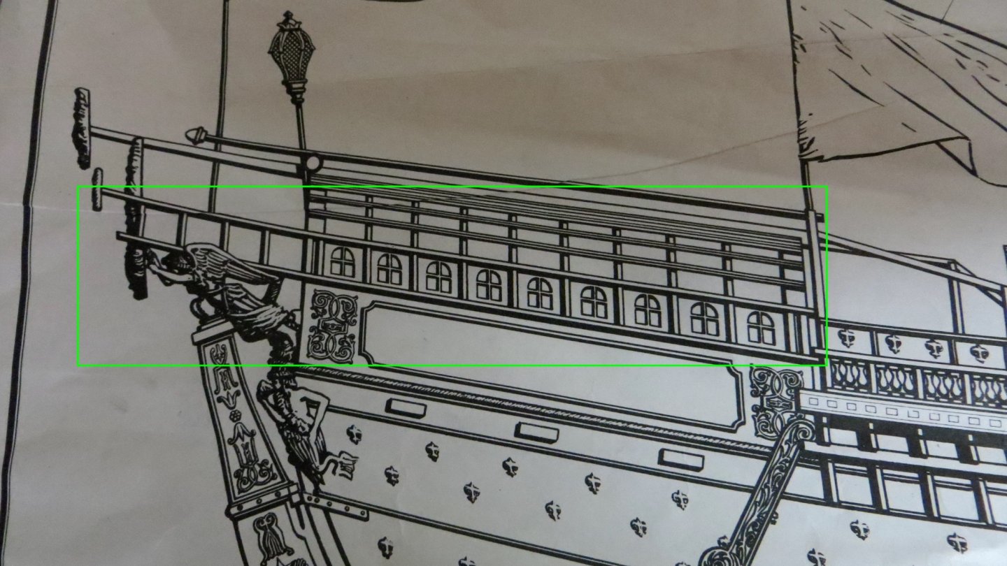
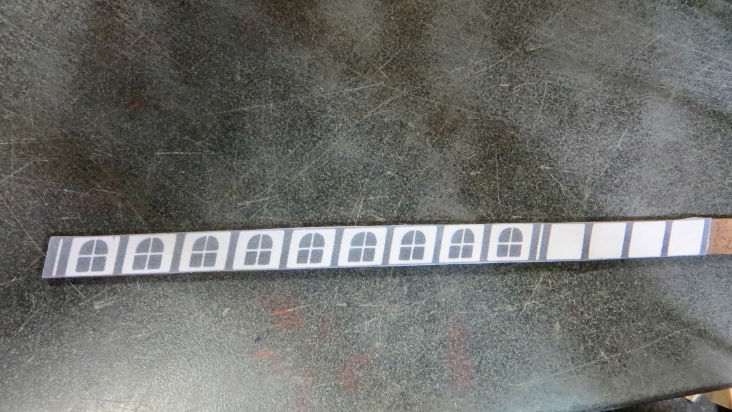
Hello, Glad that visitors like the carvings! Thanks for the input and for visiting. Small update: As can be seen on this photo below, I thankfully, and with relief, was able to pry the carving off and re-position it right side up! Crisis averted. Both the Corel plans and the Fleur di Lis plan show 3 small hatches under the decorative side panels. The Fleur di Lis plan shows the hatches to be more oval in shape (as I made them) than the rectangle shape of the Corel plan. Another difference is that the Fleur di Lis plan show 2 of the hatches roughly where I put them (see green arrows). The one I marked with the red arrow is located more forward(Past the stern yoke). I could not do this however, since I have 5 knees supporting the upper deck in this area, while the Fleur di Lis plan shows only 1 knee. So I kept the 3 hatches in the locations shown on the Corel plan. Added some thin wire to simulate hinges. Starboard side I did a test run on the Mica material, suggested to me by Michael. I glued on a few of the window cutouts from the plans to the Mica, using Elmers Rubber cement. Interestingly, when I tried sanding down the Mica to the shape of the window openings, the Mica thickness started peeling (flaking) off in sheets, like an onion. So, I will experiment later, using some microscope glass pieces I have instead. Painted and sanded the rudder decorative sheet metal. Pre-Painted the rudder Attached the decorative pieces to both sides of the rudder Now I will take a week or so off to spend time with family! Thanks, Frank


- 510 replies
-
- 8
-
-
- reale de france
- corel
- (and 1 more)
-
Excellent work! Frank
-
Oops, I'm having a bad week! Just noticed the view on the port side, I put the wood figurine upside down! Yikes! I think I need a break from ship modeling this week! Frank P.S. I was able to get the wood carving off the port side without breaking it. I will reattach right side up tomorrow!
- 510 replies
-
- 1
-
-
- reale de france
- corel
- (and 1 more)
-
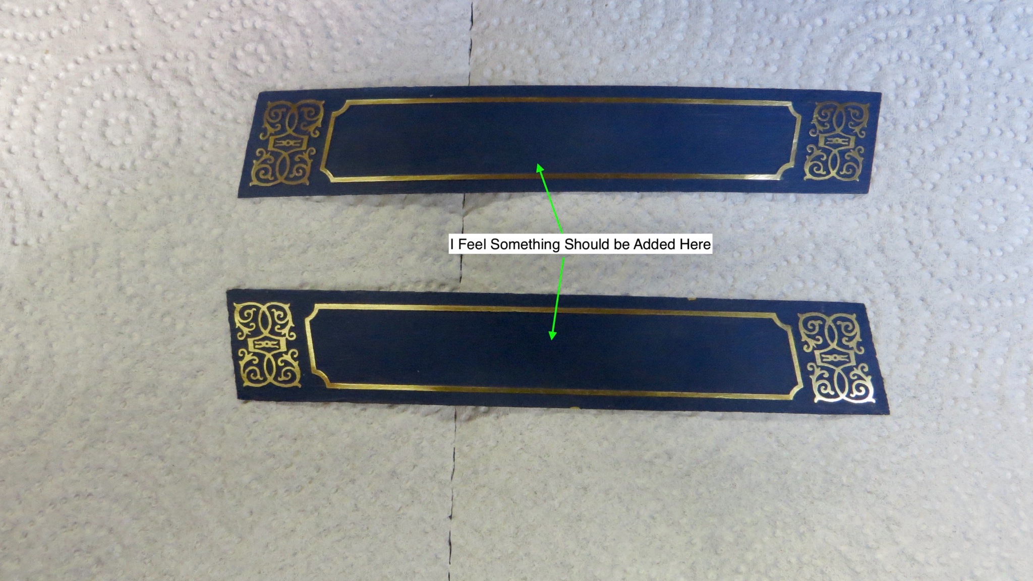
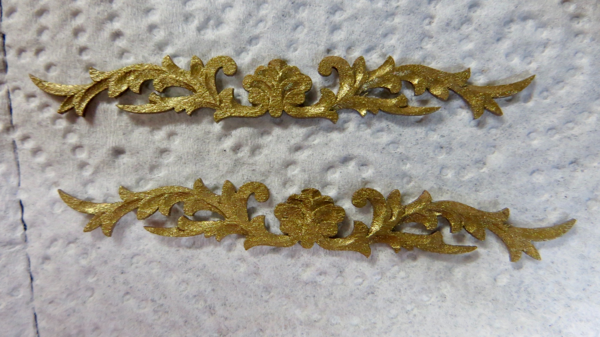
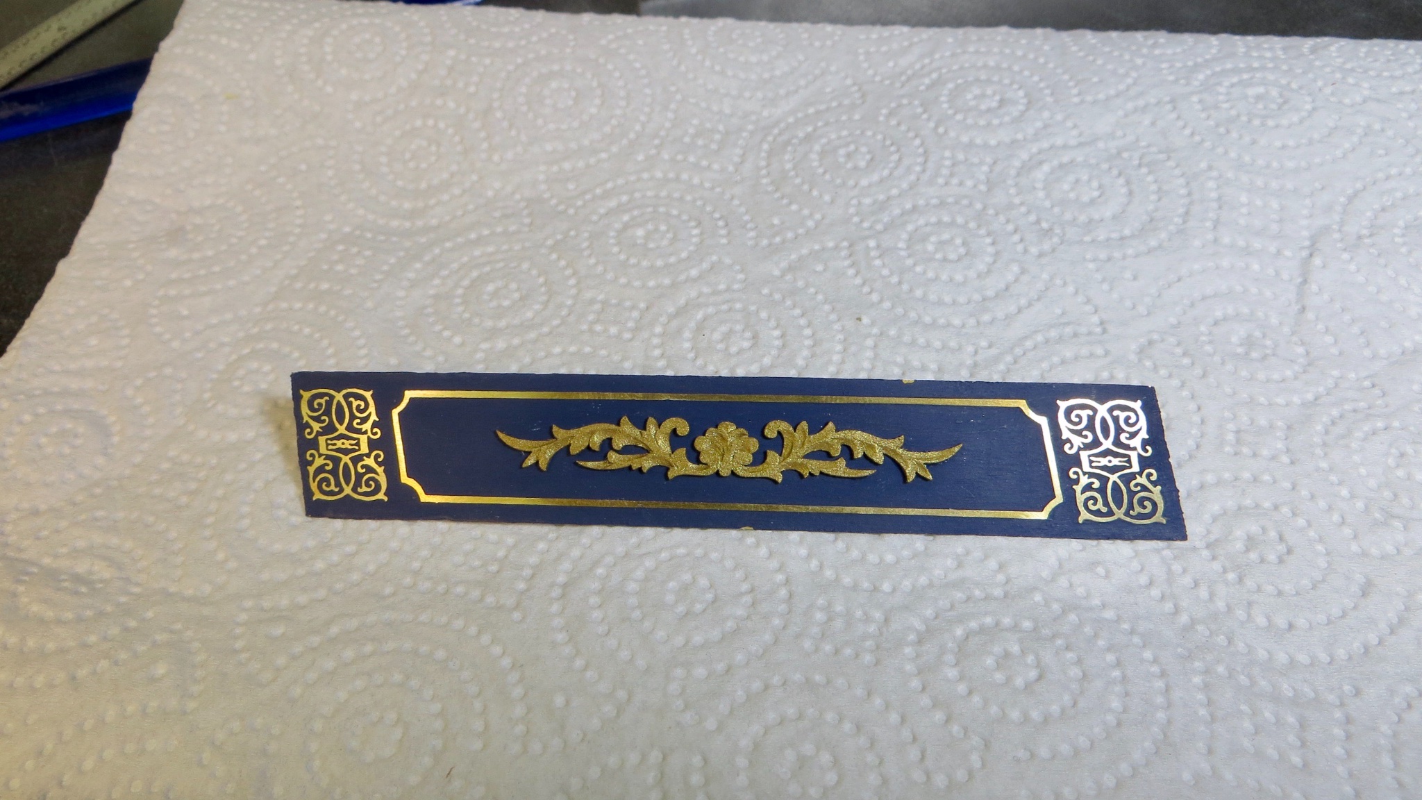
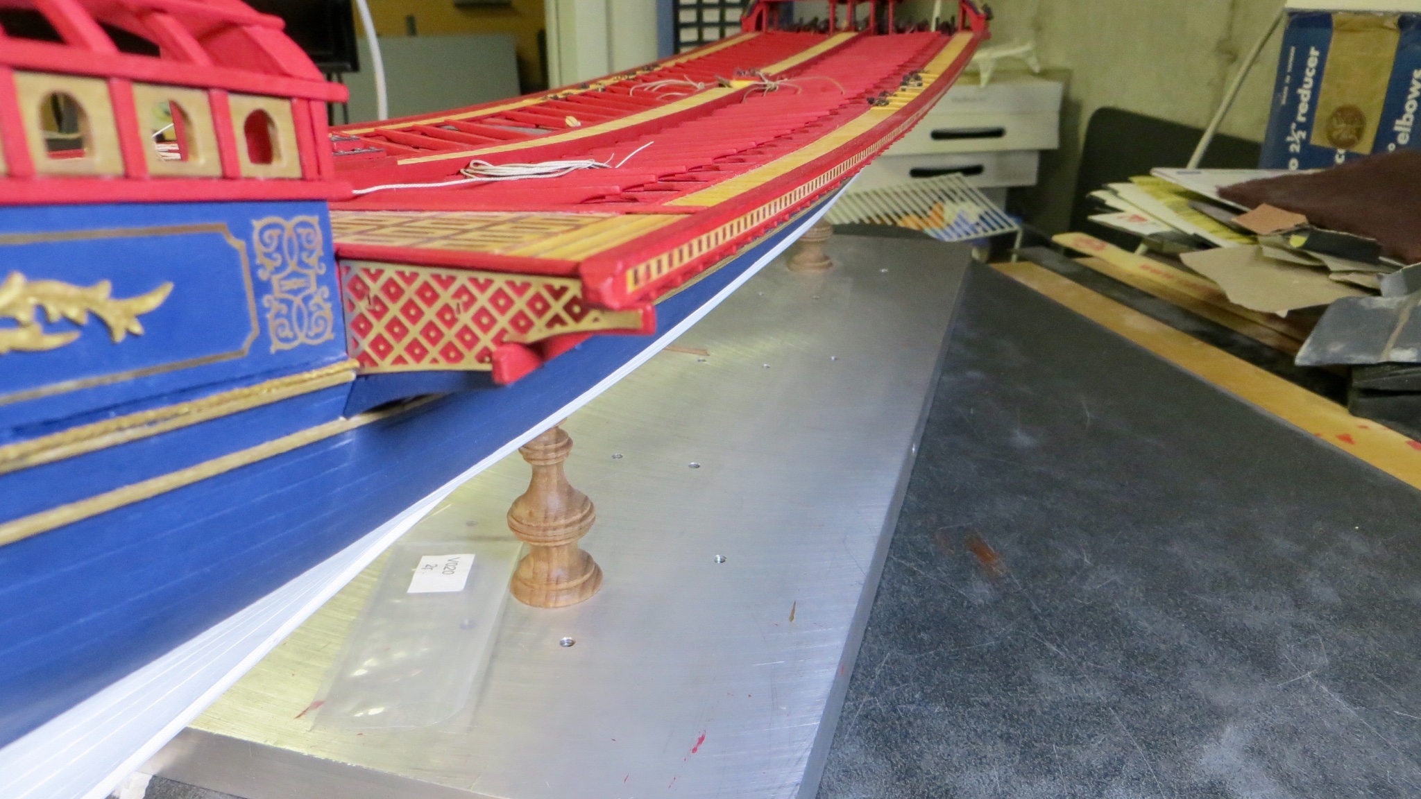
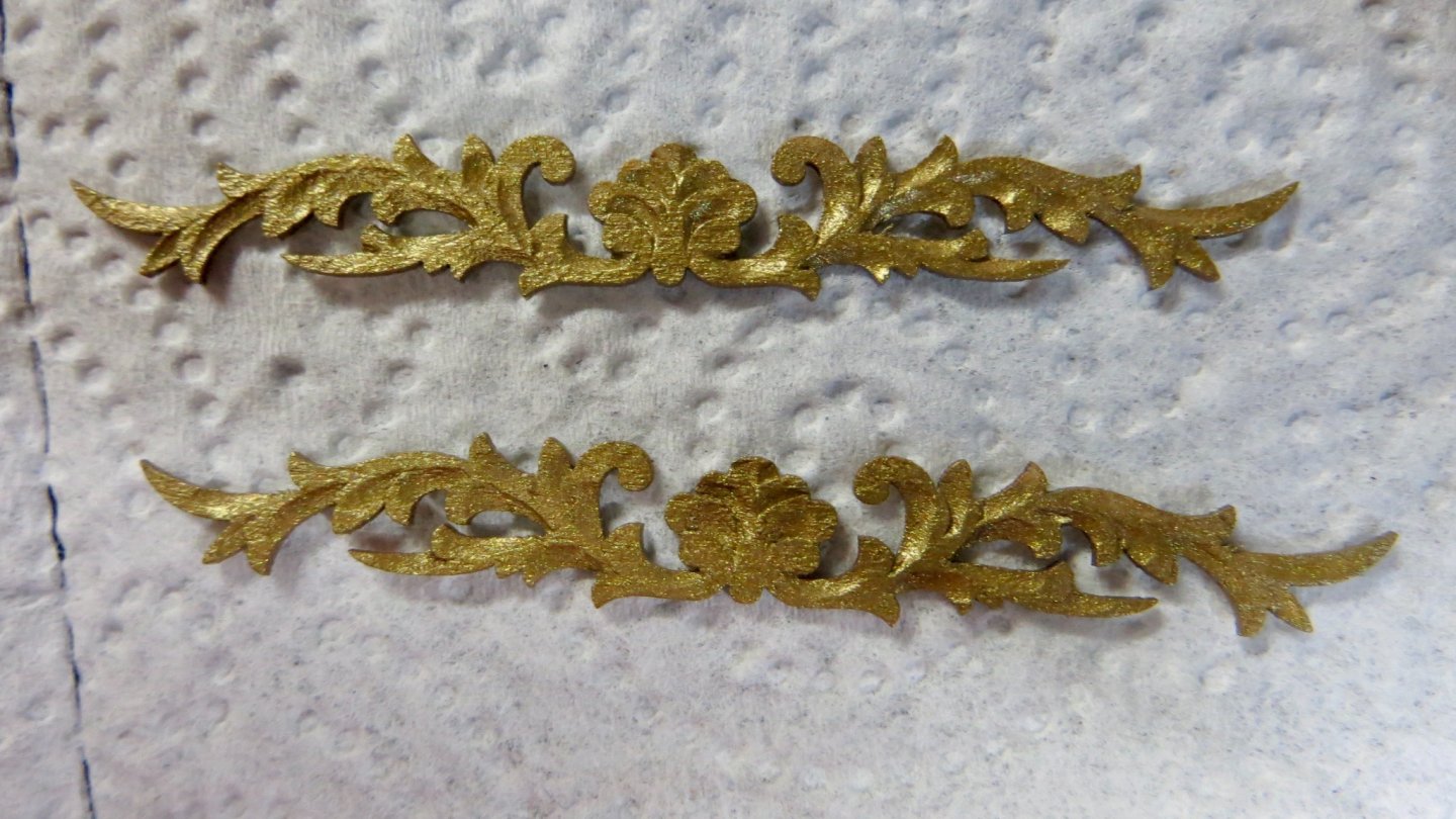
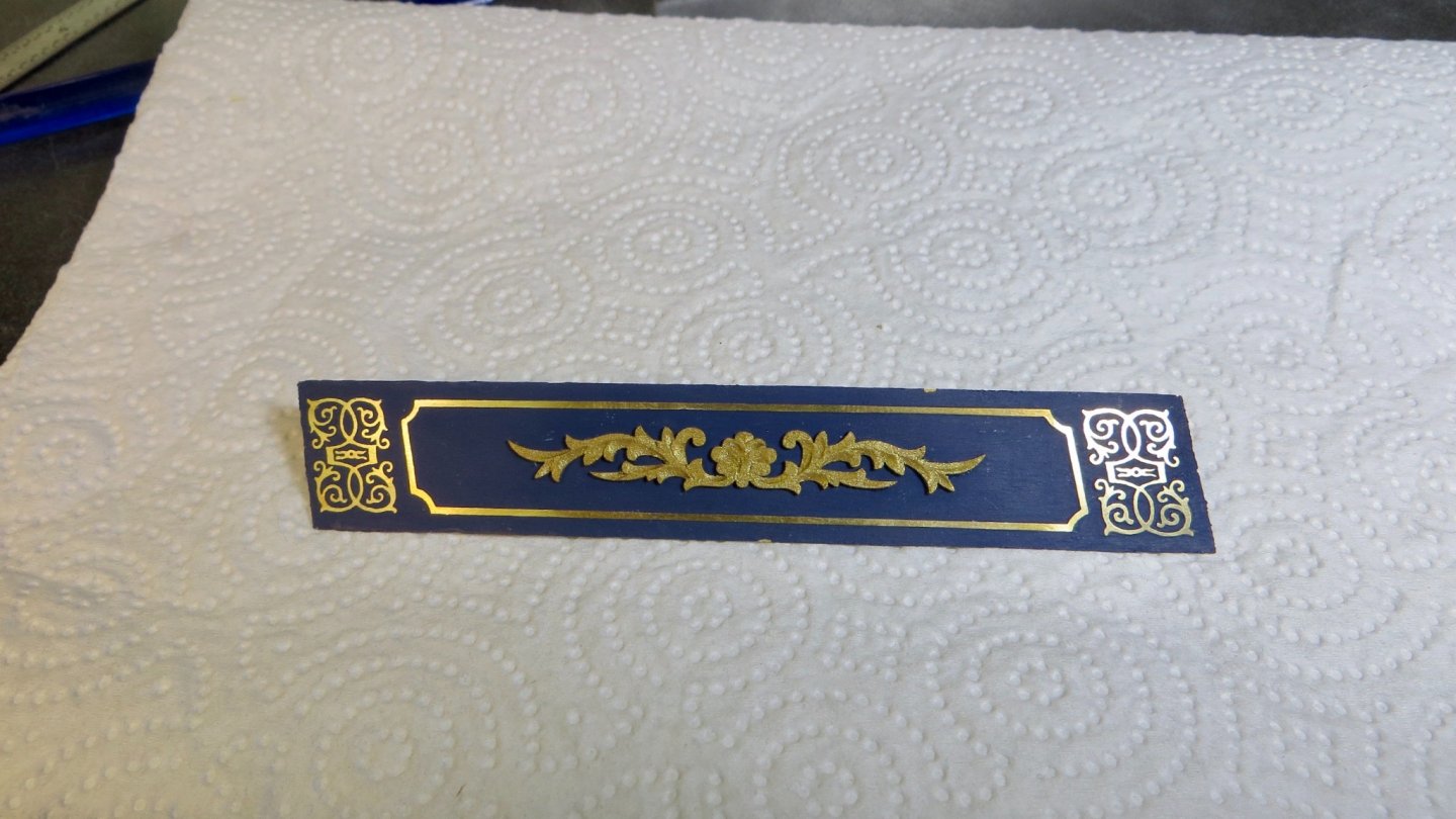
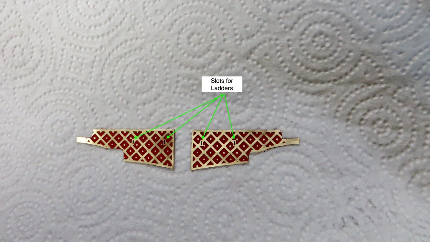
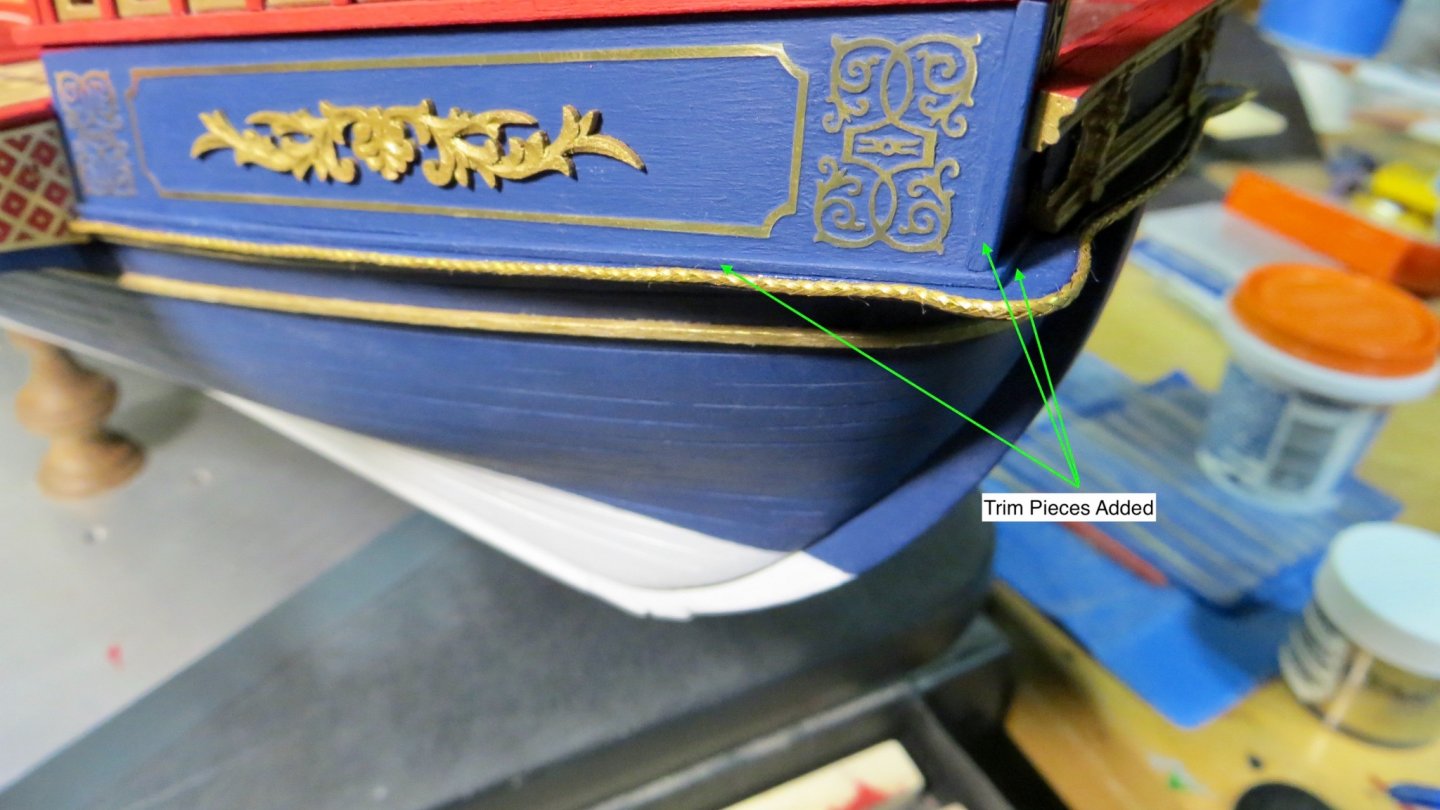
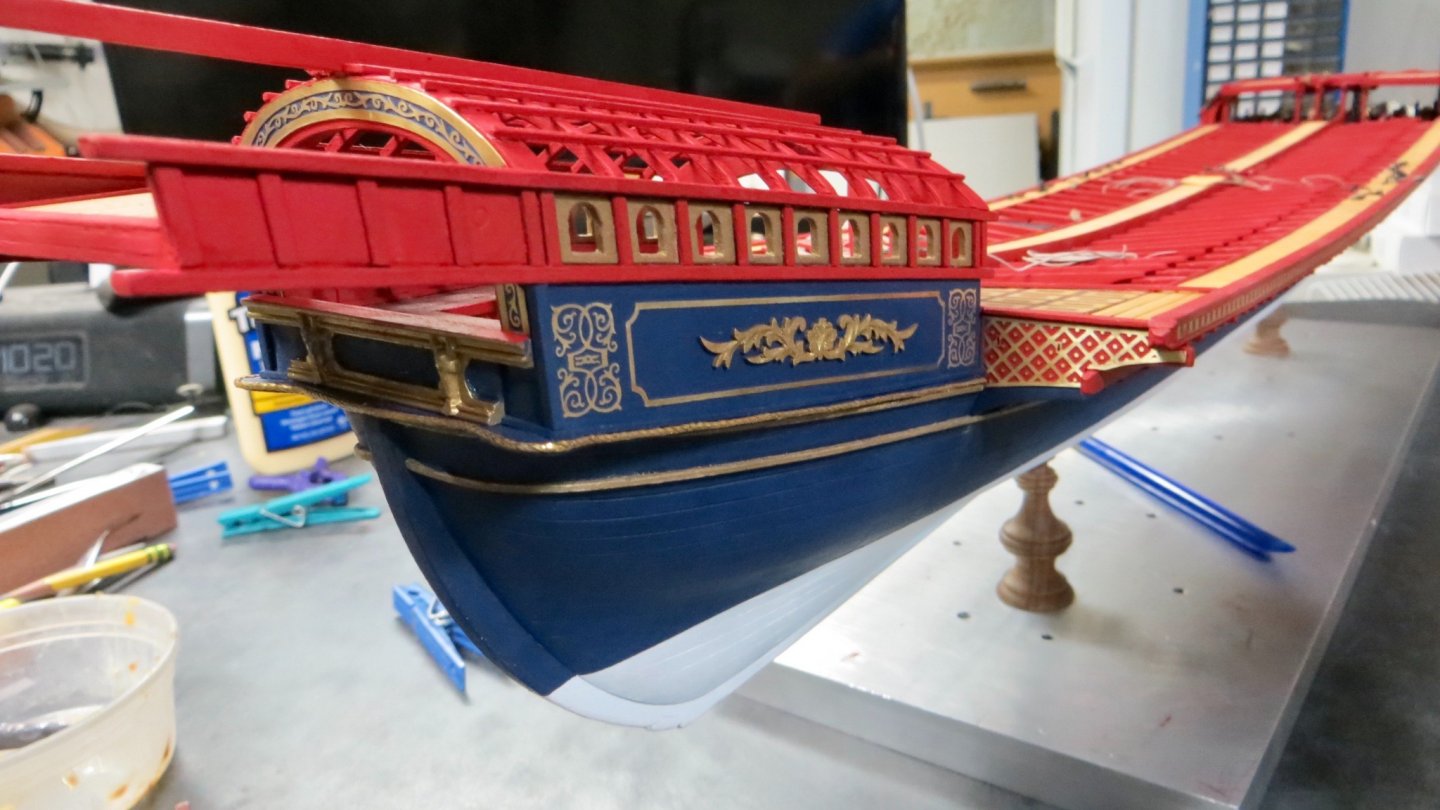
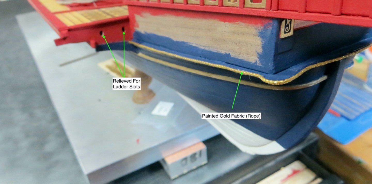
The external sides of the canopy area have some sheet metal decorative art work. Using the same technique taught to me in earlier posts, the background was painted the ship's blue. The decorative pieces have what appear to me to be a boxed frame. Feeling that something was left out, I wanted enhance these pieces. I put my wife to work and at the Etsy site, she found a company called Victoriaminiland, located in Victoria, Canada. They have some beautiful thin delicate wood art pieces that we thought would fit perfectly in the space. This is what we picked out. (Photo shows wood art painted with the Antique Gold) Wood art glued to sheet metal decorative piece. Stern facing decorative sheet metal painted the ship's red. Note the slots where the ships ladder will fit into. In an earlier photo, I show the drilled relief in the wood that this piece will sit on. Piece attached to stern yoke. When the sheet metal decorative pieces were attached to the sides of the model, I didn't like the look of the edges of the sheetmetal. therefore some trim pieces were added to give it a more finished look. Finished area on Port side. Finished area on Starboard side: After taking a few days off for Turkey Day, my goal for the next month or so is to a) Finish the 6 (3 on each side) port opening lids b) Play around with the Mica, suggested to me by Michael, to see if a window look added to the side panel arches are possible and c) Start work on the rudder assembly. Thanks again for the input and suggestions, Happy Thanksgiving! Frank


- 510 replies
-
- 8
-
-
- reale de france
- corel
- (and 1 more)
-
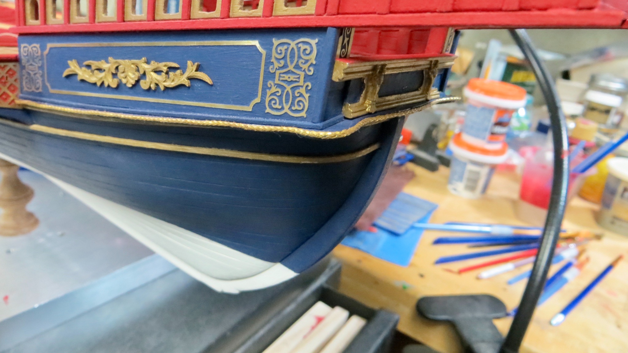
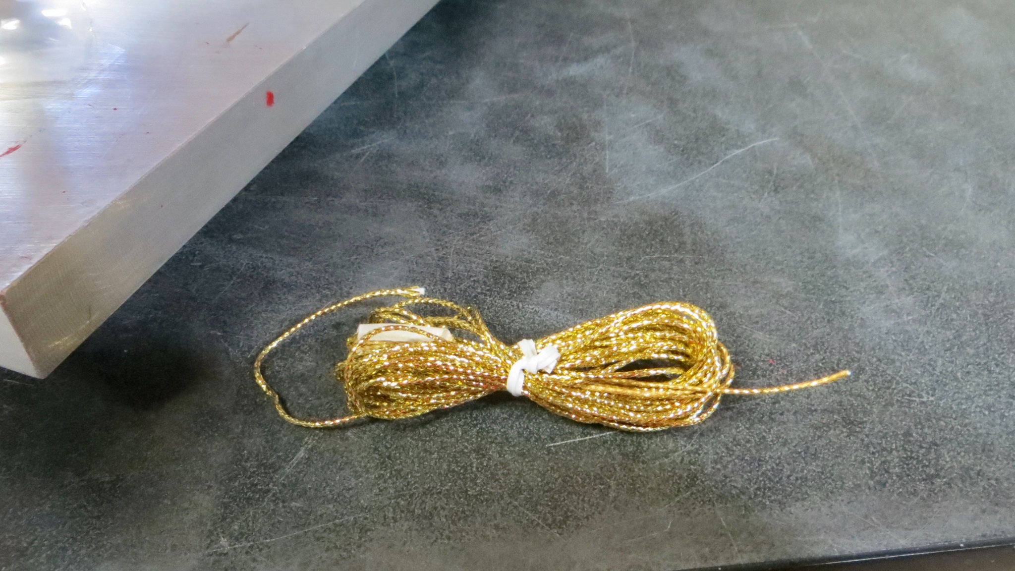
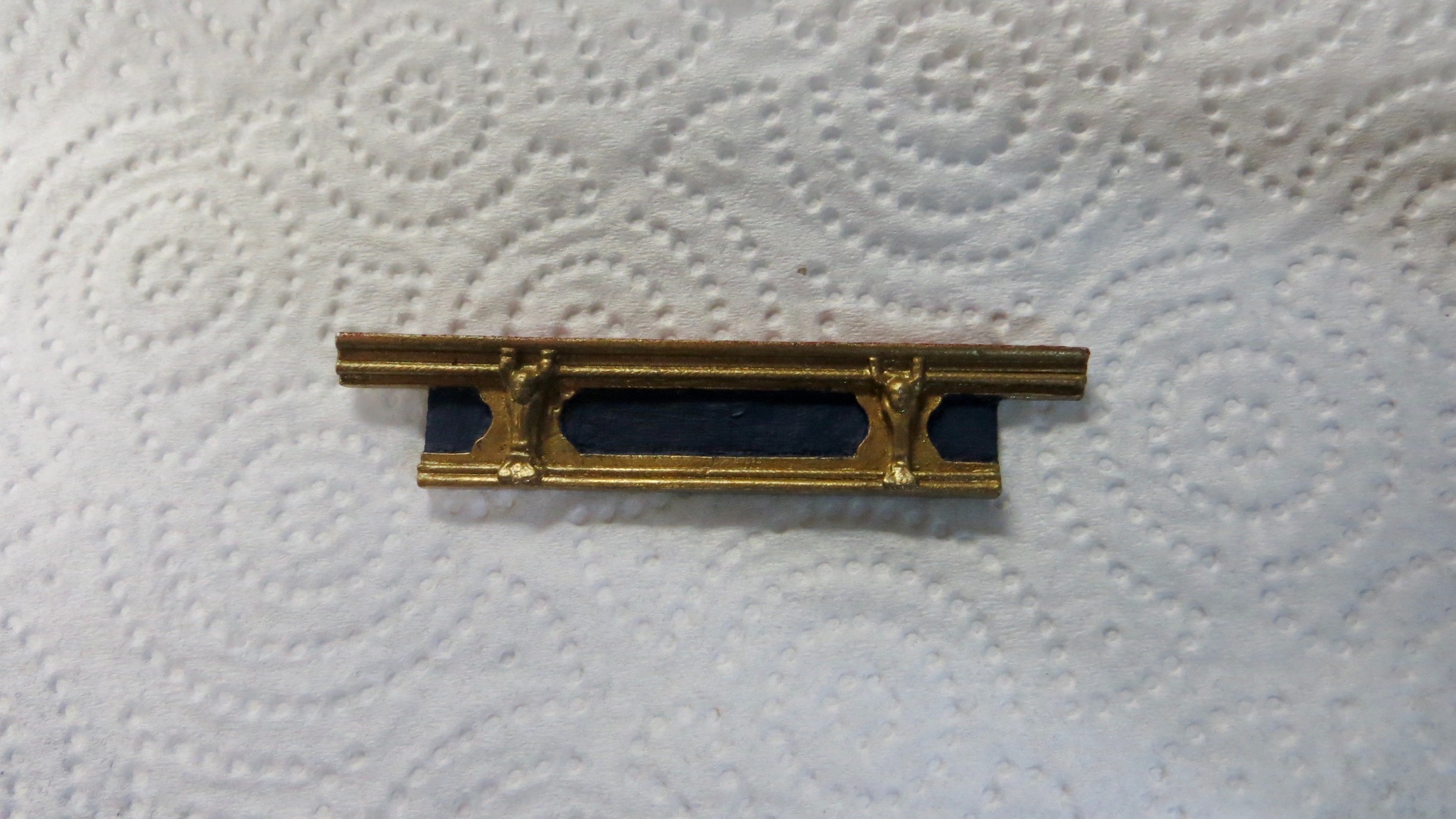
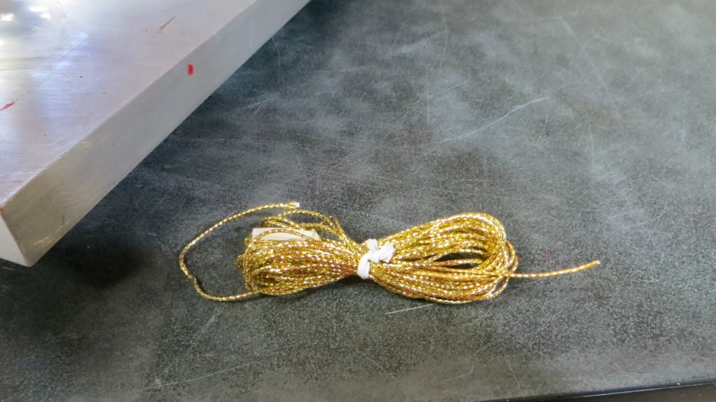
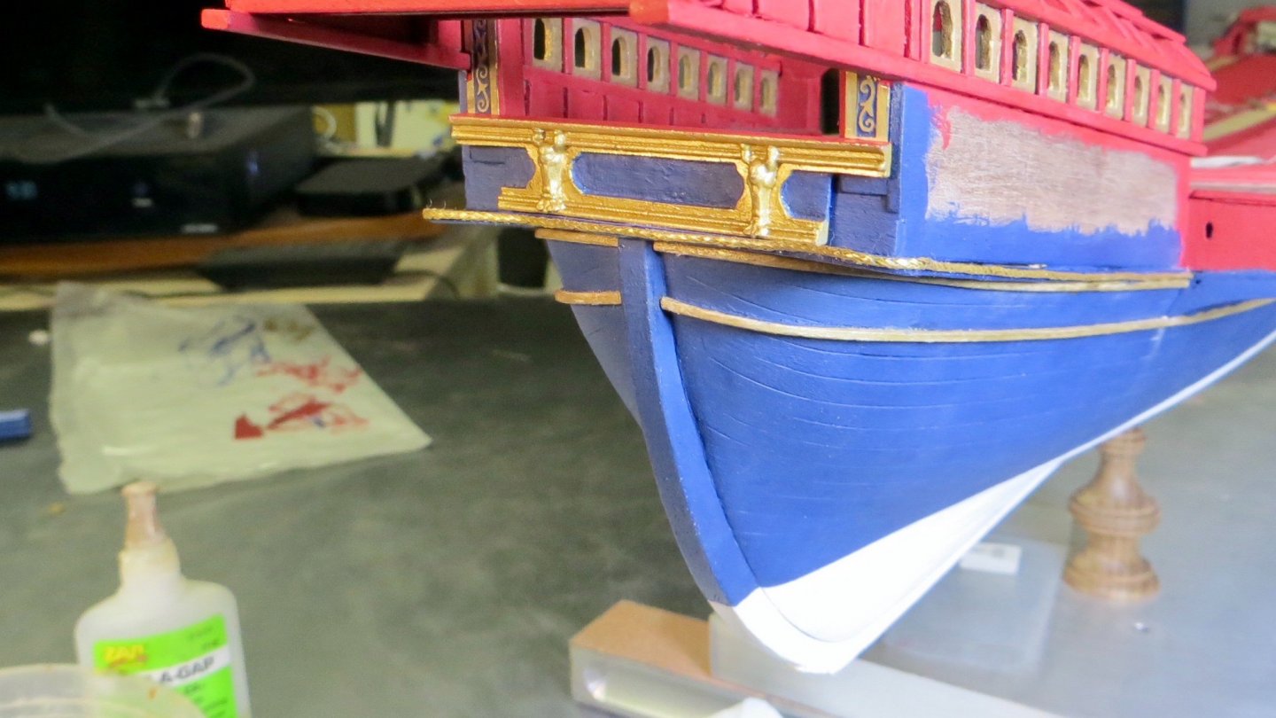
Hello, Updates: So after looking at Gimo's critique in the post above and with gentle nudging from my wife, I took on the task of dismantling and rebuilding (reworking) the canopy arches. Grudgingly, I must admit that I'm glad I did Thank you Gimo for pointing out that my work could be better! I spent a few long nights shortening some of the arch ends and lengthening a few and then with careful sanding, putting it all back together. Here are the results: Anyway, Time to move on! The Corel kit supplies some decorative gold rope to be added as trim. The gold was way too shiny for my tastes, so I figured out the length I needed for the stern and painted the line with the Antique Gold I have been using. (Photo is before painting) The painted decorative line added to the edges of the stern lip. There is a metallic decorative piece that is fixed to the stern of the canopy area. Decided that I should add this now, before the rudder assembly is attached. Again, The metal was too shiny for my tastes, so I painted the piece with the Antique Gold and the blue paint I have been using. The piece added to the stern of the model.


- 510 replies
-
- 4
-
-
- reale de france
- corel
- (and 1 more)
-
Hi Clark, Here is a photo of the Fleur De Lis rudder. It looks to be the same or similar as the Corel plan. Frank
- 112 replies
-
- 2
-
-
- corel
- reale de france
- (and 1 more)
-
Thanks for the photo Clark! Looks nice. Strange that the rudder tiller seems to go into the Royal seating area. Did the king steer the boat? Lol! Joking! I'll try to be more careful with the sheet metal. thanks for bringing the issue up . Frank
- 112 replies
-
- 1
-
-
- corel
- reale de france
- (and 1 more)
-
Hi Clark, Yes, the sheet metal is real flimsy! Do you have any photos of the upper part of the rudder assembly? I will have to start working on that soon. thanks, Frank
-
Hi Michael, I just received the pieces of Mica in the mail. When I finish the area of the model I am working on and do some repairs spotted by Gimo, I will see if I can make some use of the Mica. I am trying to think of a way to attach the window opening pattern copied from the plans onto the Mica and then grinding to shape. If I can find some glue that will come off the Mica when I'm done shaping, I think it might work! Thanks Frank
- 510 replies
-
- 2
-
-
- reale de france
- corel
- (and 1 more)
-
Hello Gimo! Thanks for stopping by. Also I appreciate your input. So, I checked the model and there are no dips on the left (Port) side. The Longitudinal planks are straight and do not dip. I do think, however, you are really talking about how the arches sit on the upper rail plank. I noticed that some of the arches reach almost to the end of the railing and some end in the middle. Good catch! You have a good eye! I made the arches 2mm thick, but neglected to grind the tips on some of them to the 2mm thickness. So, after I finish with my current work in progress, I will sand down some of the longer ones and build up the 1st two a little to make them more even going along the side. I didn't think they were that noticeable, but I guess I was wrong. LOL!! Thanks again for the positive input. Appreciated! I hope all is well in your neck of the woods. Frank
- 510 replies
-
- 1
-
-
- reale de france
- corel
- (and 1 more)
-
Welcome! I look forward to watching your progress with the Billings kit! Have you been to the Vasa Museum? It is definitely on my list of places to visit in the future. Good luck, Frank
-
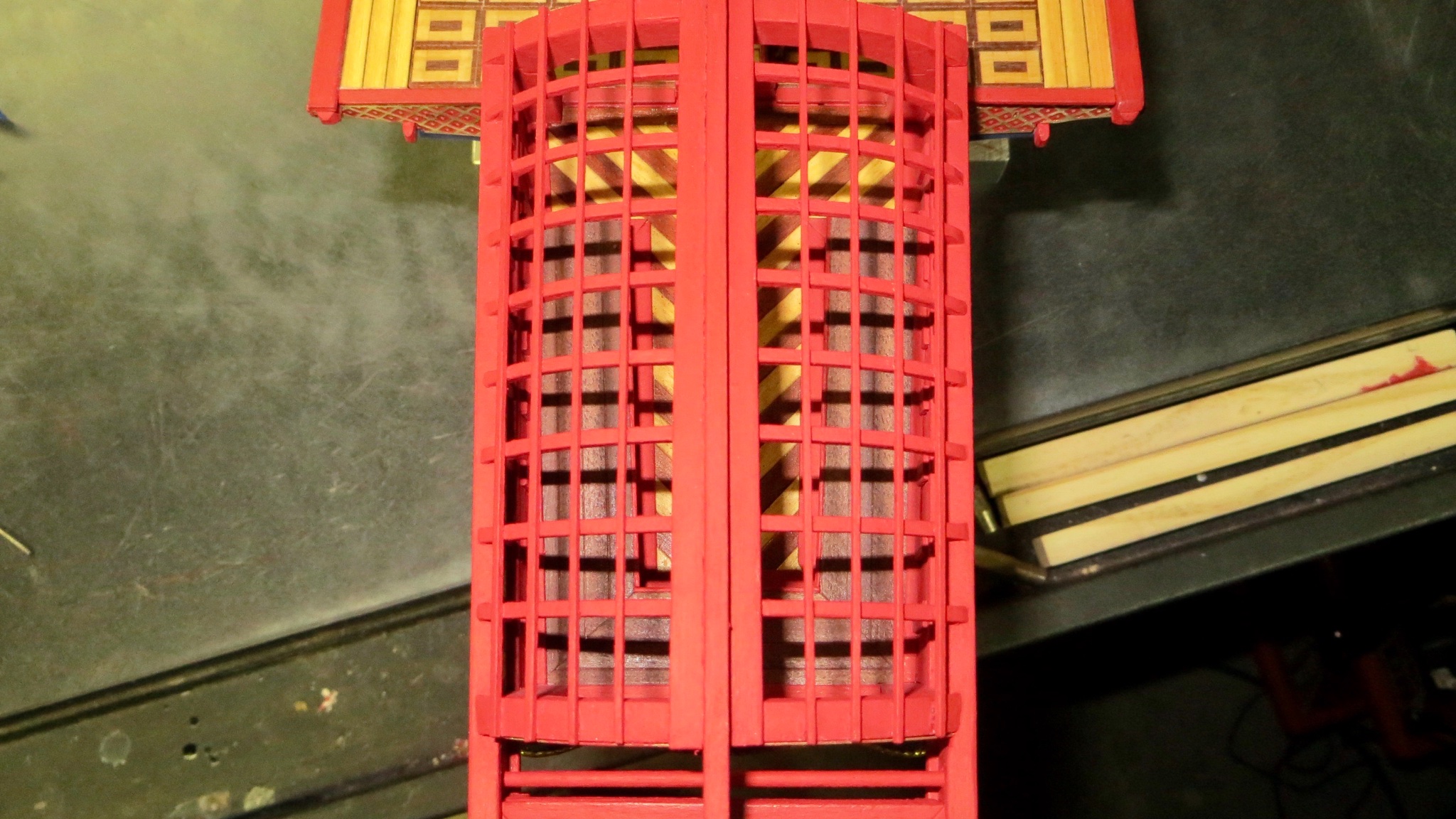
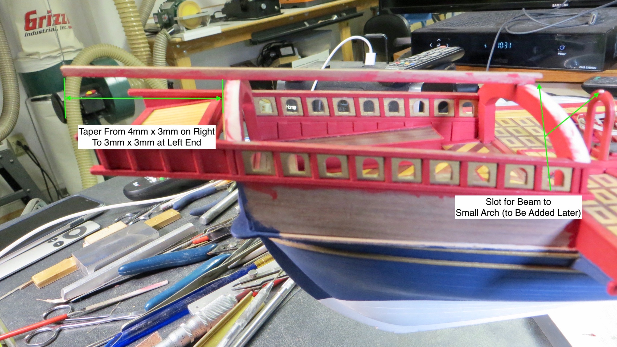
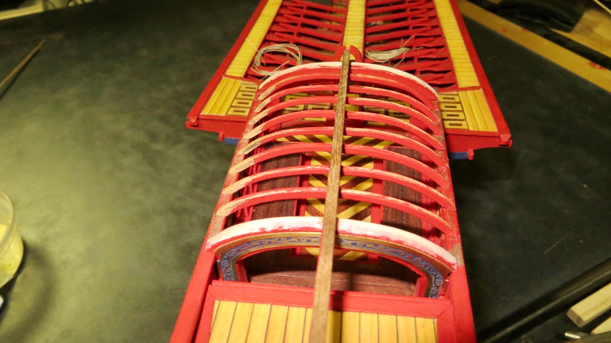
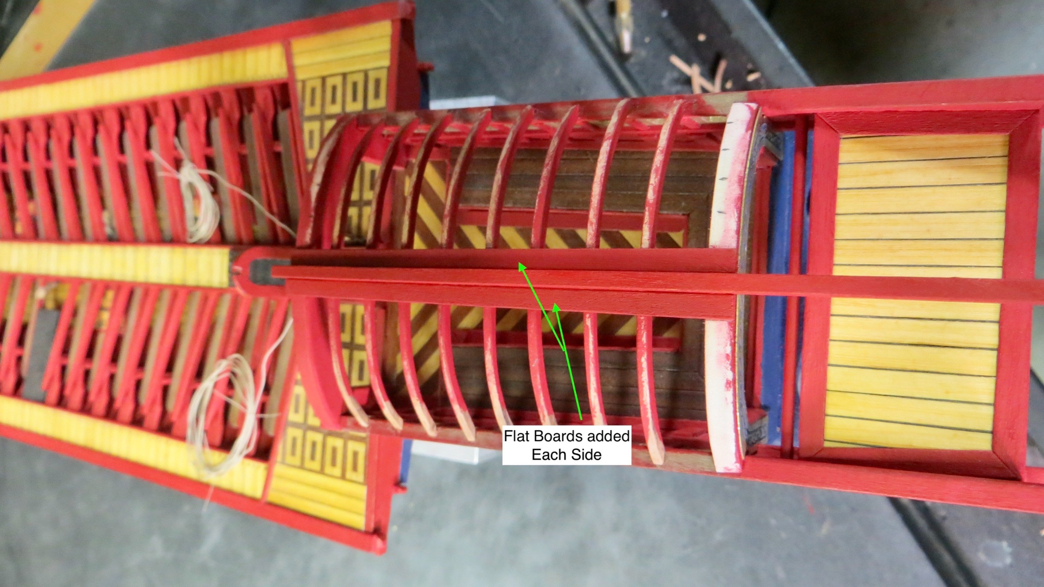
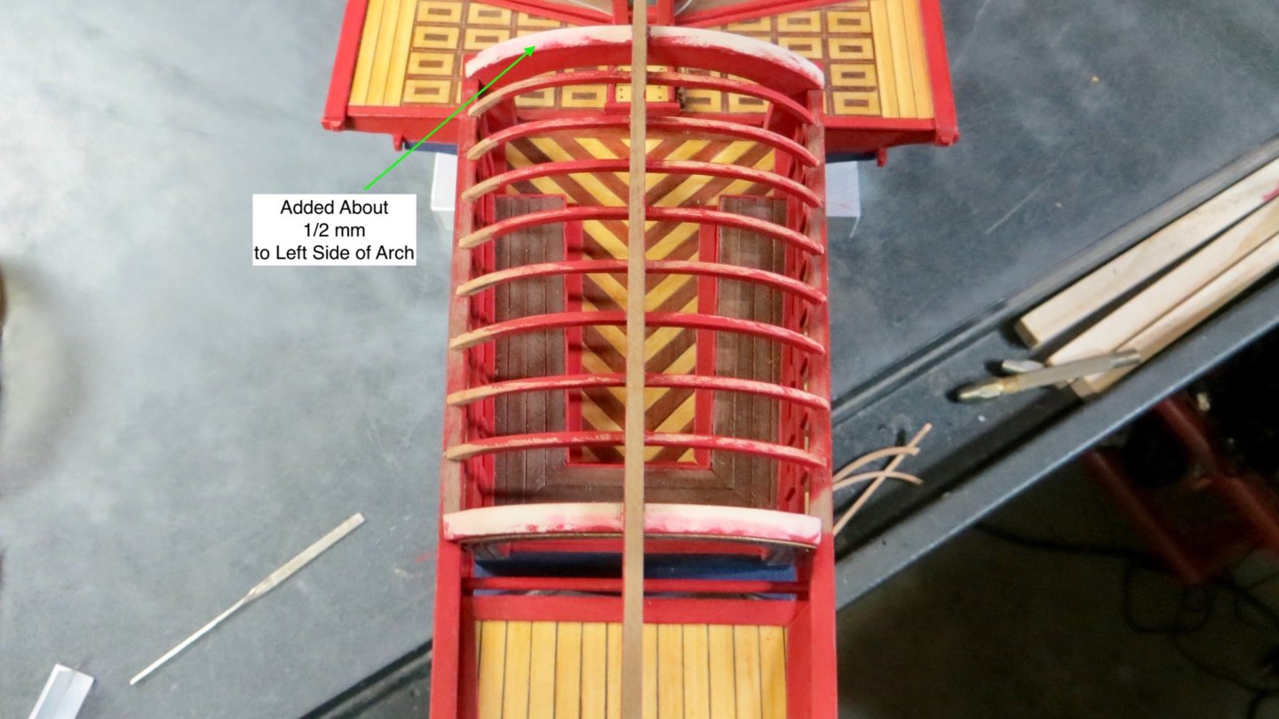
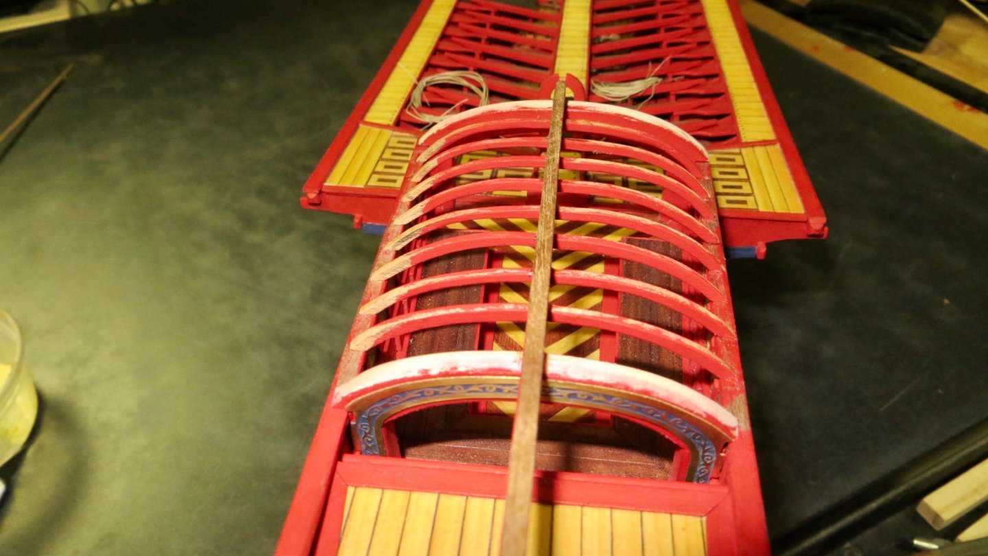
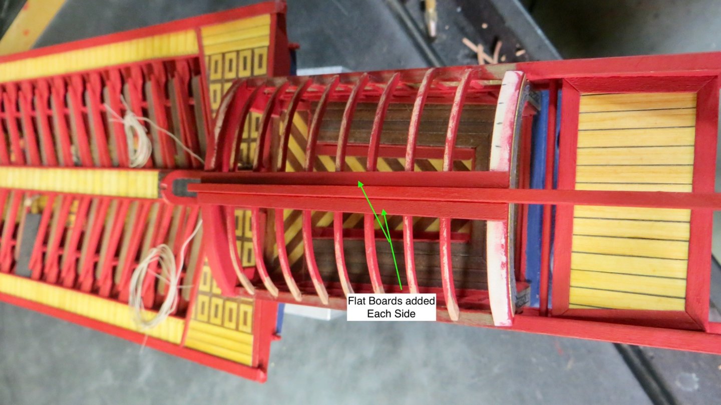
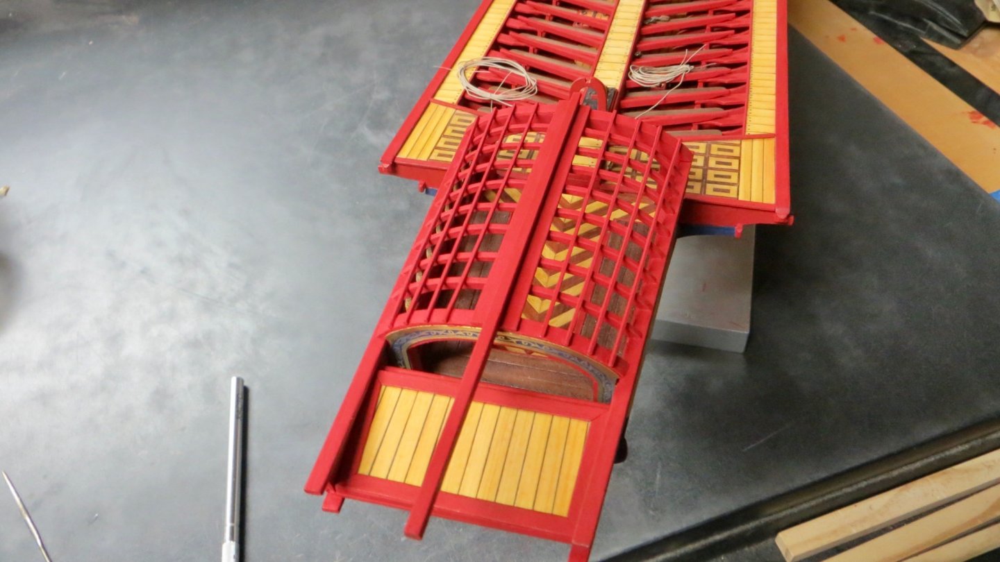
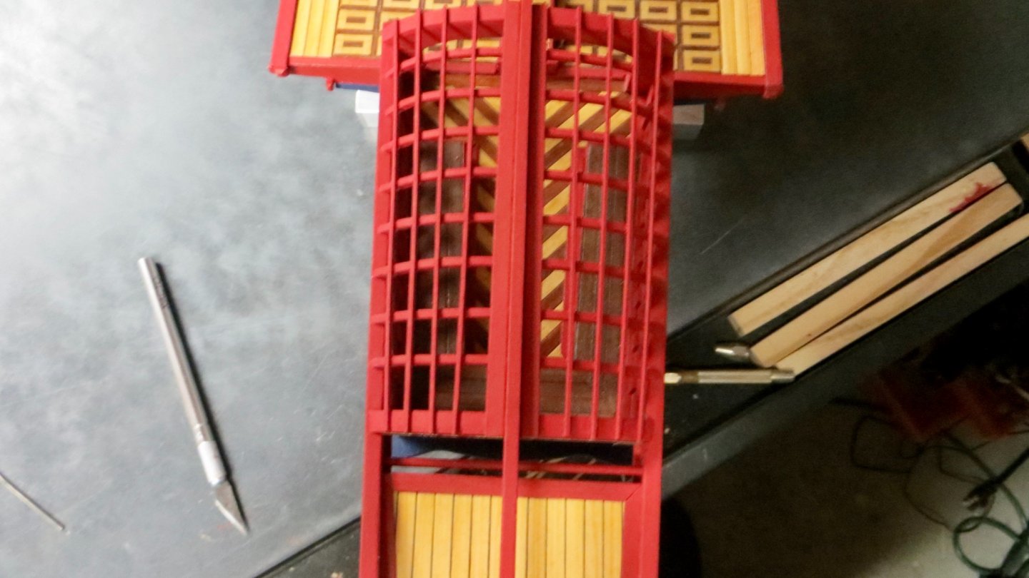
Thanks to all for stopping by and the "Likes". Appreciated as always! Michael, Mica is on order and just shipped. When I receive it, I'll play around with it and see how it goes. The method I chose to use for making the 8 arches seemed to work and (I believe) came out well. Finished forming the 8 arches and trial fitting them. I pre-painted the areas that will be hard to get to after installation. Next step was to mount the main beam at the centerline to the correct length. A slot cutout was added on the front end for the mounting of a smaller beam later to the small arch at the right. The main beam was tapered down, from the back of the stern arch to the left end. Wood beam tapered from 4mm x 3mm to a square 3mm x 3mm as shown on the Corel plans. A cast figurine will be added later on the aft end. The 8 arches were added by glueing to the underside of the main beam and to both sides of the upper railings. As mentioned on the previous post, I had to build up another .5mm to the top fwd arch on the port side. I must have been too aggressive with my sanding. Flat board added on each side of main beam 8 small beams (4 on each side 1mm x 1mm) added. The fwd arch is wider than the stern, so these pieces are tapered towards the stern. All painted and finished. Now to start working on the outside areas of the stern section. Thanks, Frank

- 510 replies
-
- 8
-
-
- reale de france
- corel
- (and 1 more)
-
hi Michael, A quick thought. Do you have a thickness sander? If you thinned down the pear wood might you be able to put a veneer on top of the upper and lower gun deck areas? If you don't have a thickness sander, and if you think it might work, you could always send me some pear wood and I could thin them down to about .5 mm or so for you. Just a thought, Frank
-
Thanks Michael. I'll definitely give it a try! Frank
- 510 replies
-
- 2
-
-
- reale de france
- corel
- (and 1 more)
-
Looks good Clark! Glad the flexible wood worked out for you! Wish me luck! Lol! Frank
- 112 replies
-
- 1
-
-
- corel
- reale de france
- (and 1 more)
-
Thanks for experimenting Michael. I will try to get some on order to experiment with! talk soon, Frank
- 510 replies
-
- 1
-
-
- reale de france
- corel
- (and 1 more)
-
Hi Michael, Thanks for dropping in and for giving me great ideas as always! How thick is the Mica? Also if you are looking at the window from both sides, how would you glue it on? My biggest issue is this. The "Fleur de Lis" plan does not call for any windows at all, just railing posts holding the upper and lower rails. I wanted to do it that way (I think Clark, on his log, will be doing it with the railing posts), but I didn't want the edges of that rear platform I just finished to be seen. So I compromised by just creating openings(without windows). Sort of a mix between the 2 plans. Anyway, I will order some of that Mica tonight and try cutting them to the exact opening of the ports and see if I can glue the Mica in so it looks good from both sides. If I can do this, I think it will look better than the way it is now!! Thanks again for the idea. Best, Frank
-
Hi Clark, thanks for stopping by. so, so far I am finding that all the forms (8 arches) are fitting perfectly on the starboard side of the centerline. On the port side, they all seem to be a little high relative to the forward large arch (number 209). My thinking is that I sanded down the port side of item arch 209 too much. So right now my plan is to add (build up) the port side of major arch 209. We’ll see if that works. If my whole plan doesn’t work, I can always go back to the way Corel wants us to do them with the flexible wood. Thanks, Frank
- 510 replies
-
- 1
-
-
- reale de france
- corel
- (and 1 more)
-
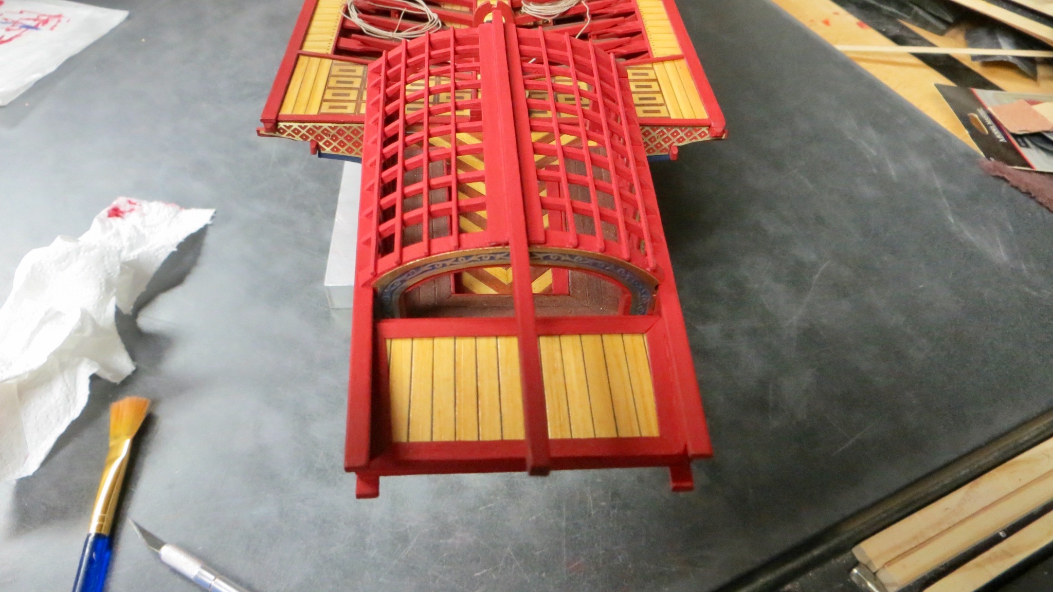
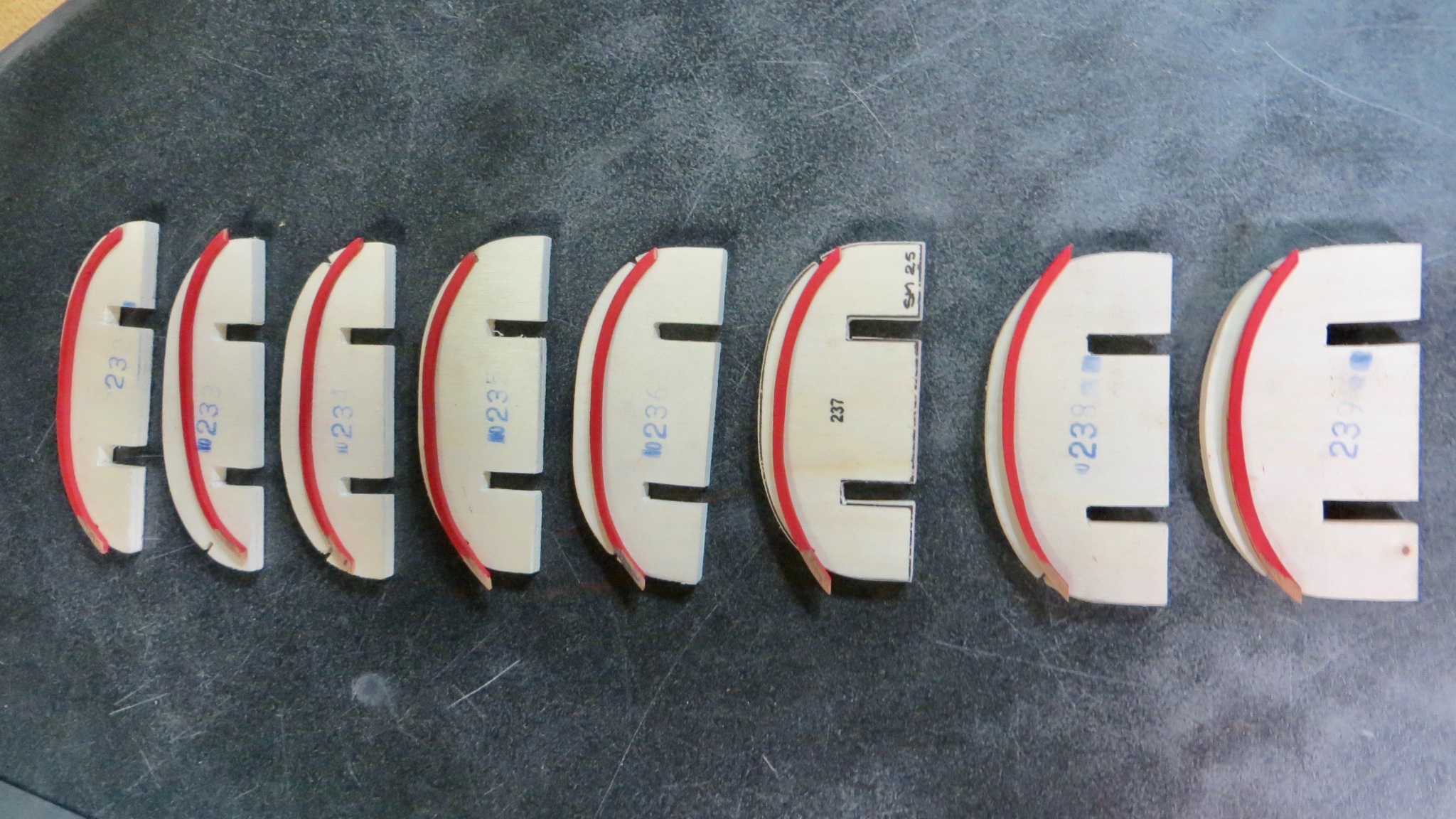
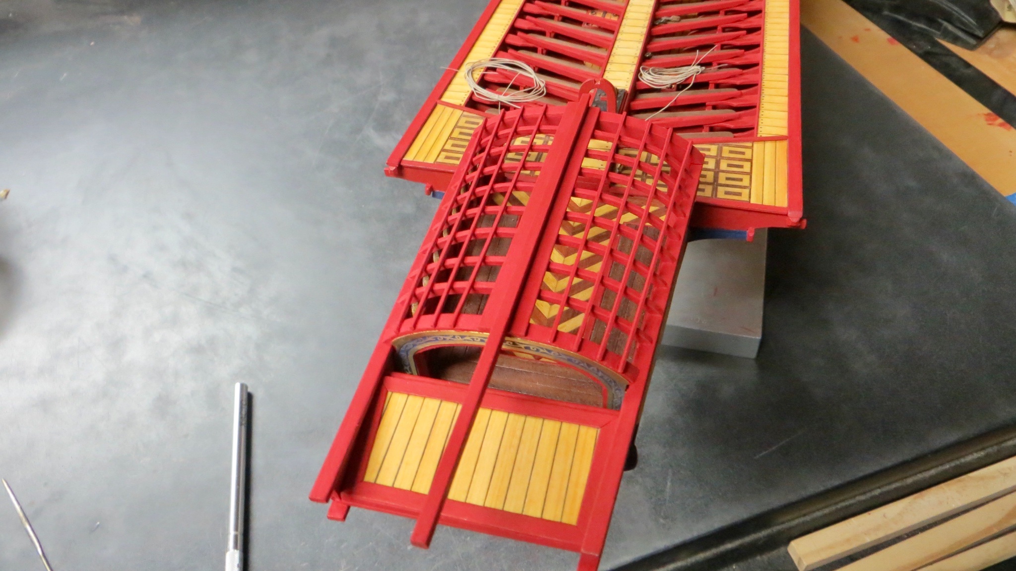
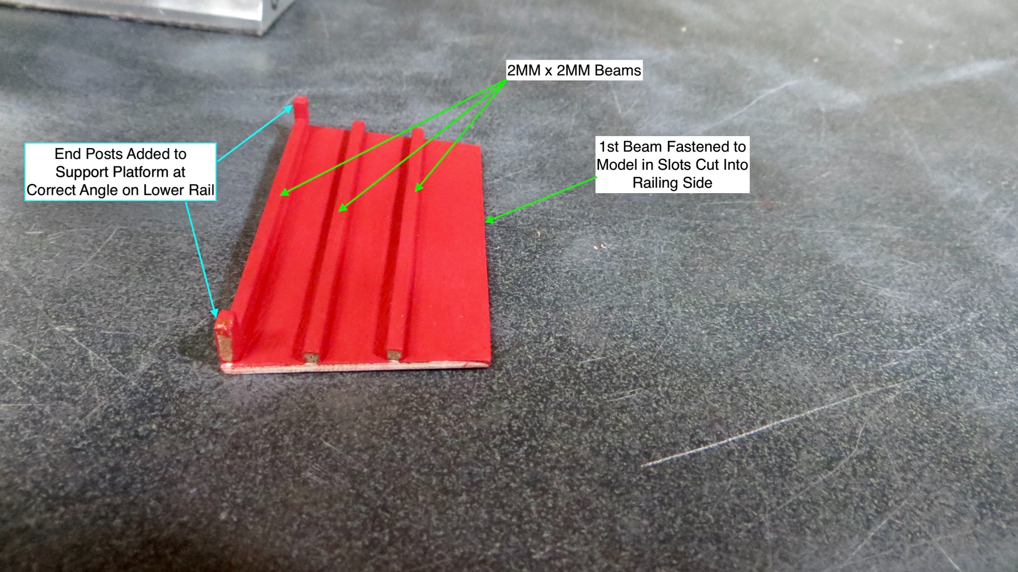
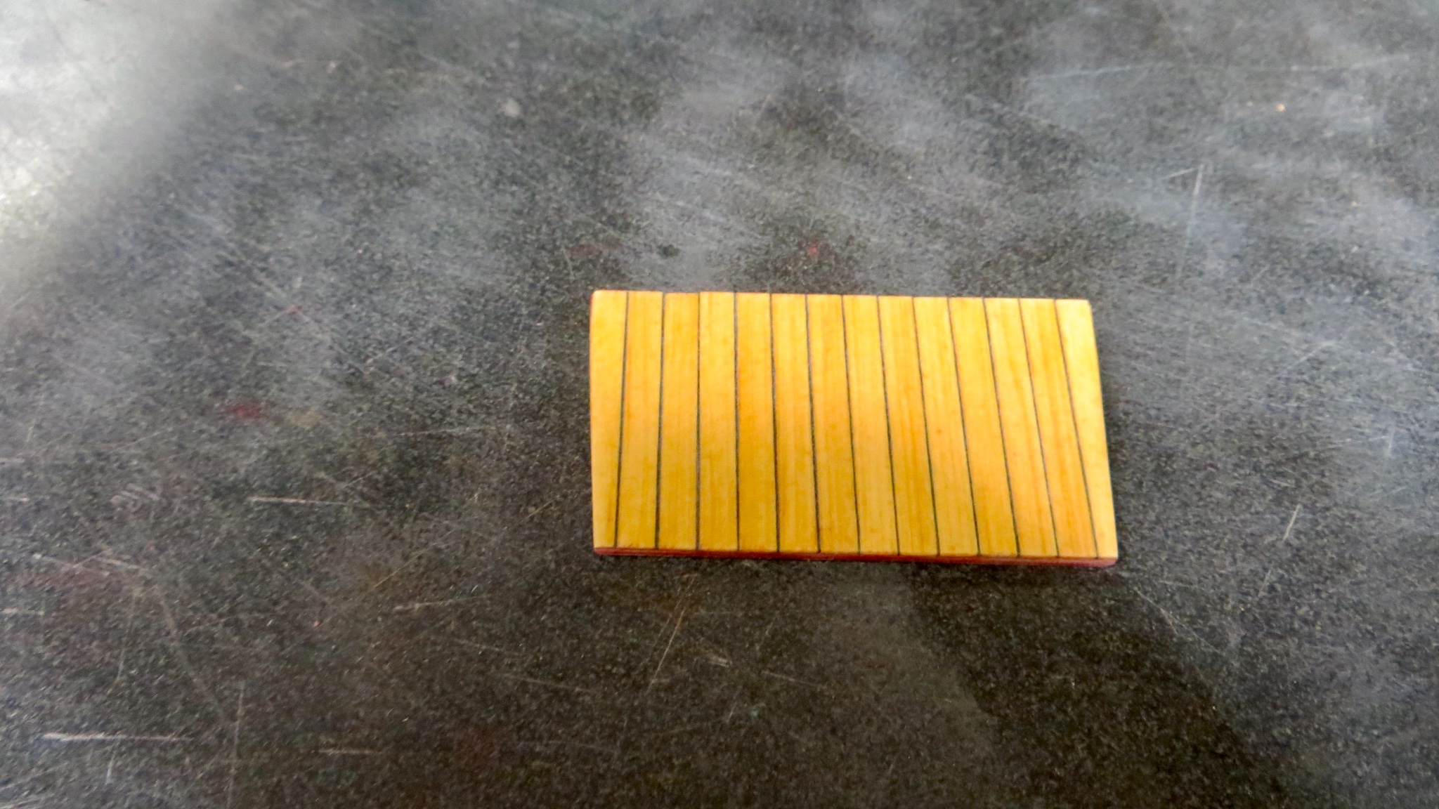
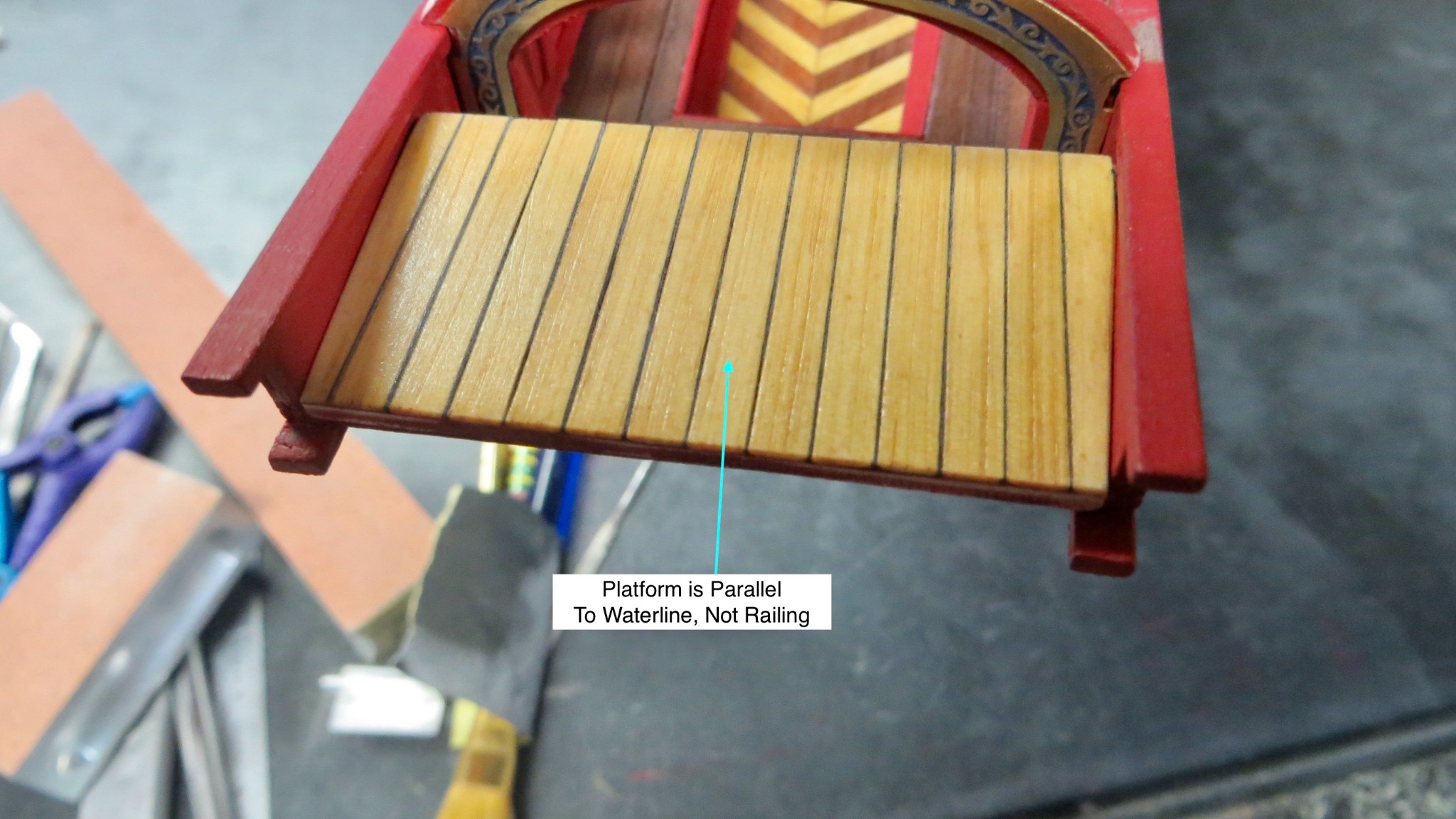
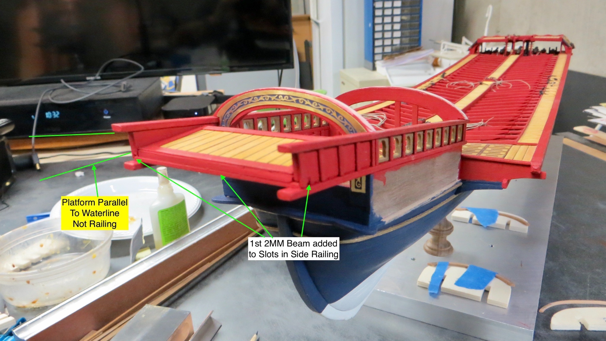
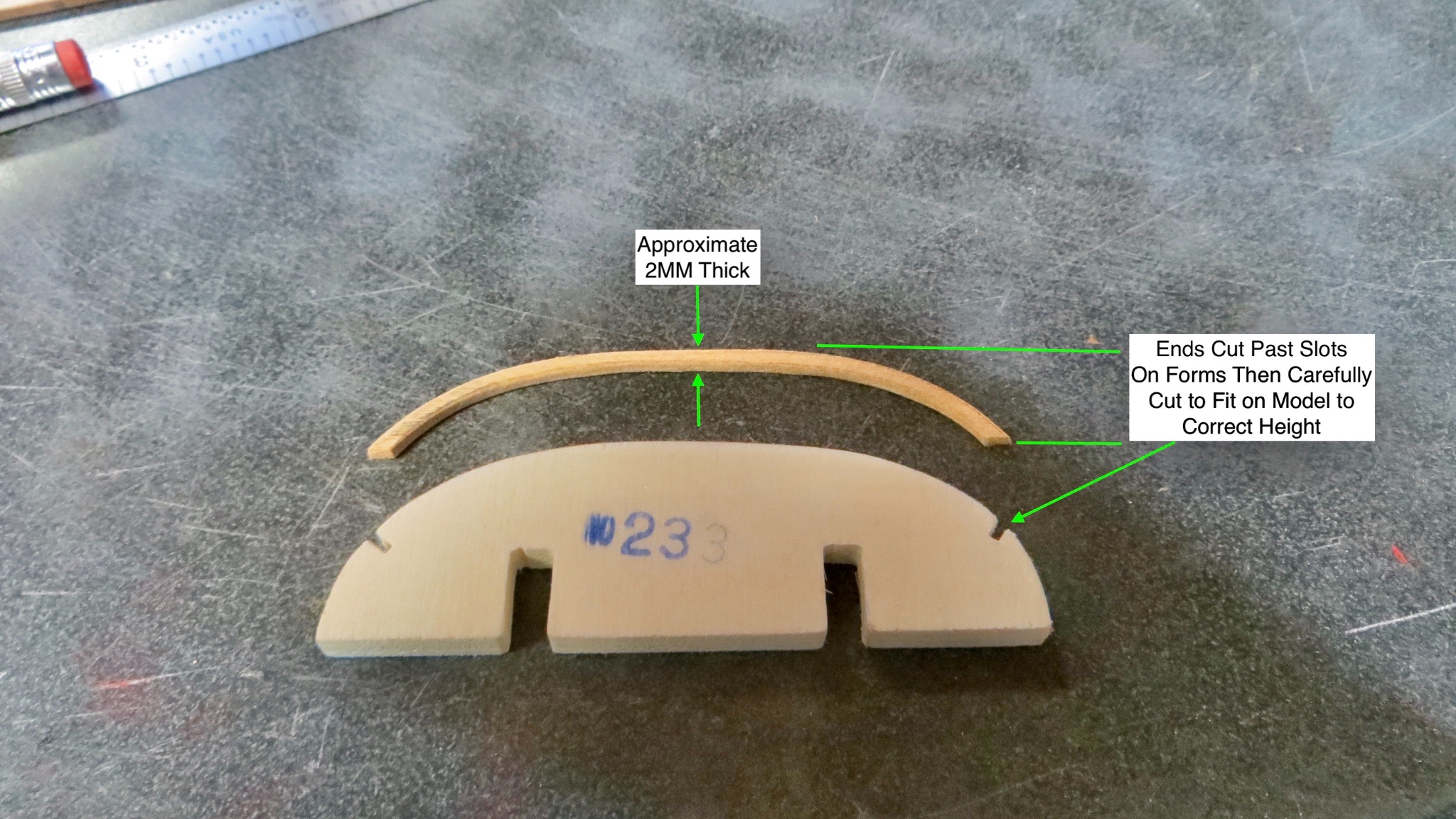
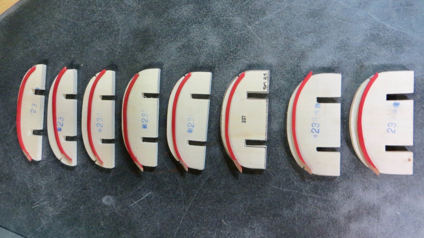
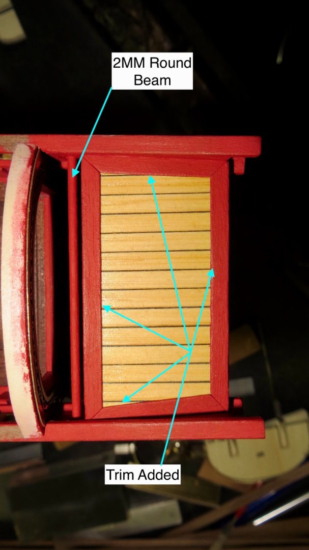
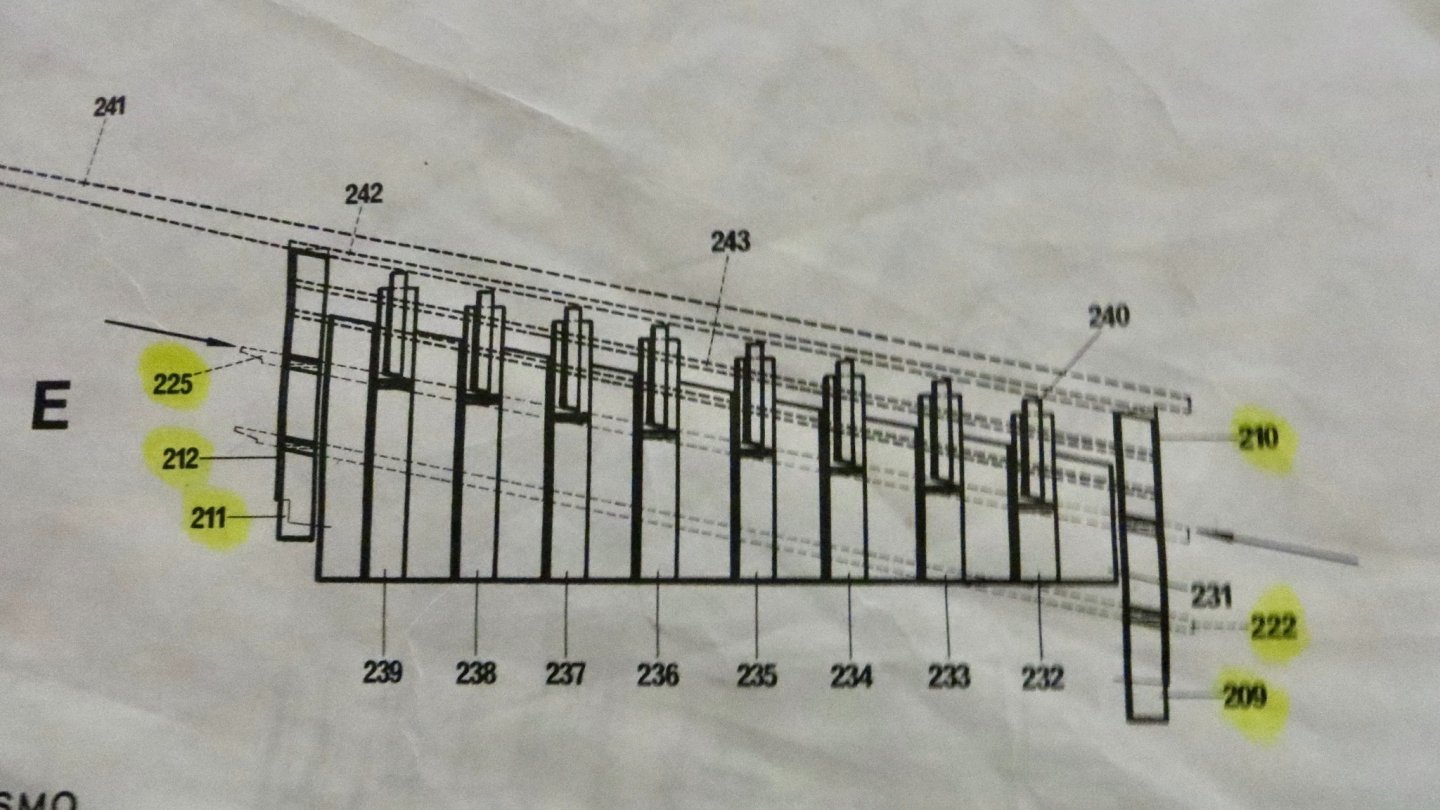
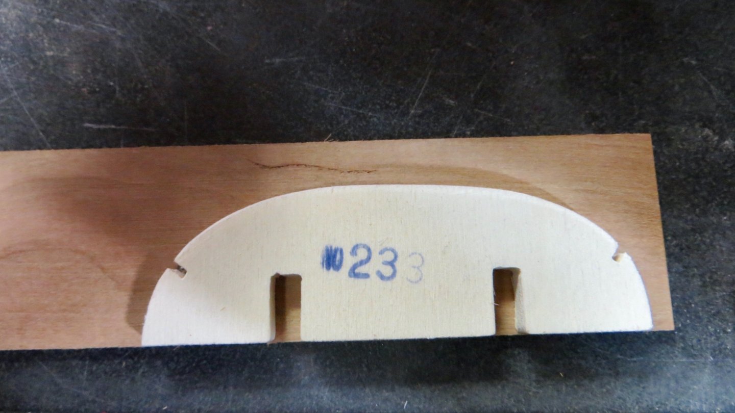
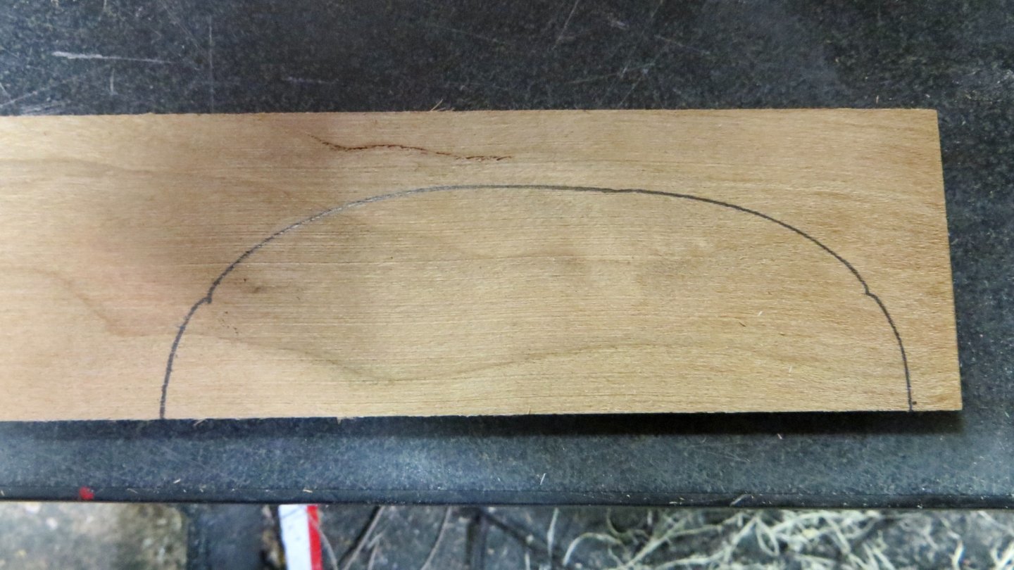
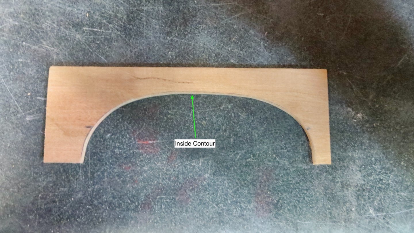
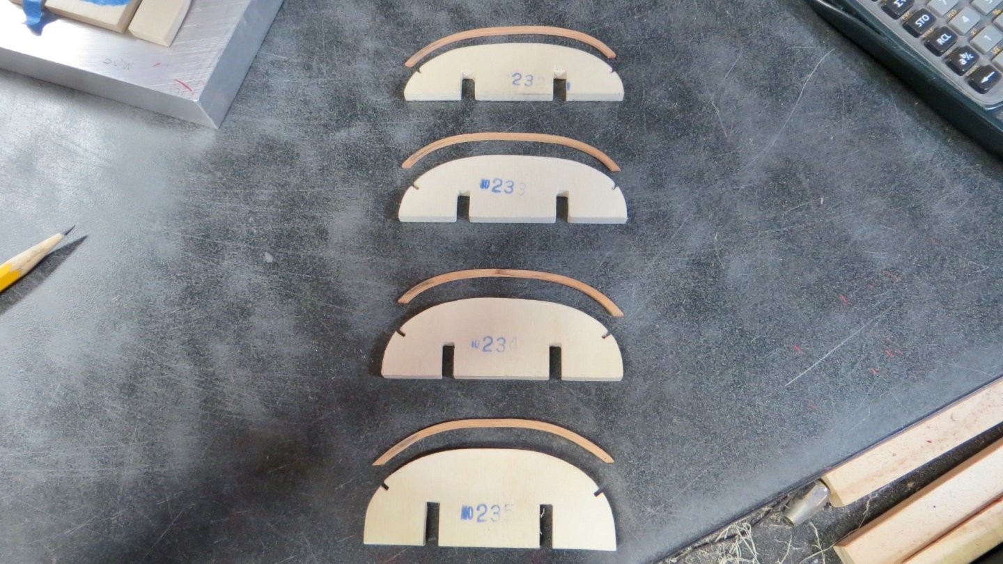
Hello, Thanks Clark and everyone else for stopping by! Began work on another platform situated behind the Royal seating area. This platform does not follow the slope of the railings. It sits parallel to the water line. The Corel kit seems to indicate that the modeler just glue the edges to the inside of the window panels on both sides. I wanted to make the platform sit more securely (It will hold a large Flag pole and flag). The plans call for 4 beams (2mm x 2mm) on the underside of the platform. I left the first one off and glued it to the side panels (as you will see in a bit) and 2 legs were added at each end of the front of the platform. These 2 legs will sit on the inside of the lower railings, allowing the platform to be at the correct angle with more support to the structure. Underside: I had to decide on what type of deck planking to put on this platform. Since I am guessing any member of royalty or person of importance would not be on this platform, It was decided to plank using the same Eastern White Pine, stained with a light oak finish. (Same as the other areas of the model). Finished Planks: Installed platform between the two side panels with legs sitting on the inside of the lower rails. The next photo shows the platform viewed from above. Trim has been added. The plans also call for a 2mm round bar to be attached to the inside of the side panels. Not quite sure yet what this bar is for, so I decided to play it safe (In case it supports some rigging etc) and drilled thru both sides of the side panels, finally sliding the bar thru in order to give it more support. View of finished platform. The angle of the platform can be seen along with the first underneath beam attached to the slots in the side panels. Now I have to start working on what I view as the most difficult part of the model: the canopy arches. Yikes! The plans call for (see next photo) 8 wooden forms (nos. 232 - 239) to be fitted onto 2 pieces (nos. 231) and sit inside the seating area. Then I am supposed to use 2mm x 2mm flexible wood and bend the arches around the frames and attach them to the ship. Once they are in place, I am supposed to dismantle the forms underneath and remove. I am not a fan of this method, because I am not crazy about leaving wood in a stressed state. So, I will spend some time and try a different way. Not sure yet if I'll be successful! First step is to trace the form on a ground 2mm piece of wood. Using a hard wood (cherry) for this. Using the scroll saw and oscillating grinder, the inside of the contour was finished. Then the outside was ground so the contour was 2mm thick. I cut each end past the marks indicated on the wood form and then kept dry fitting on the model and kept cutting back until I obtained the correct height and angle. Completed 4 of the 8 arches so far. Still have a ways to go in order for me to see if this will work. At least the arches have no natural stress in them and they should stay in position once fastened to the upper railings. Sorry for the long posting! Frank


- 510 replies
-
- 7
-
-
- reale de france
- corel
- (and 1 more)
-
Hi Michael, I like the color of the pear wood! Did the wood come with the kit or did you buy it? I hope all is well. Frank
-
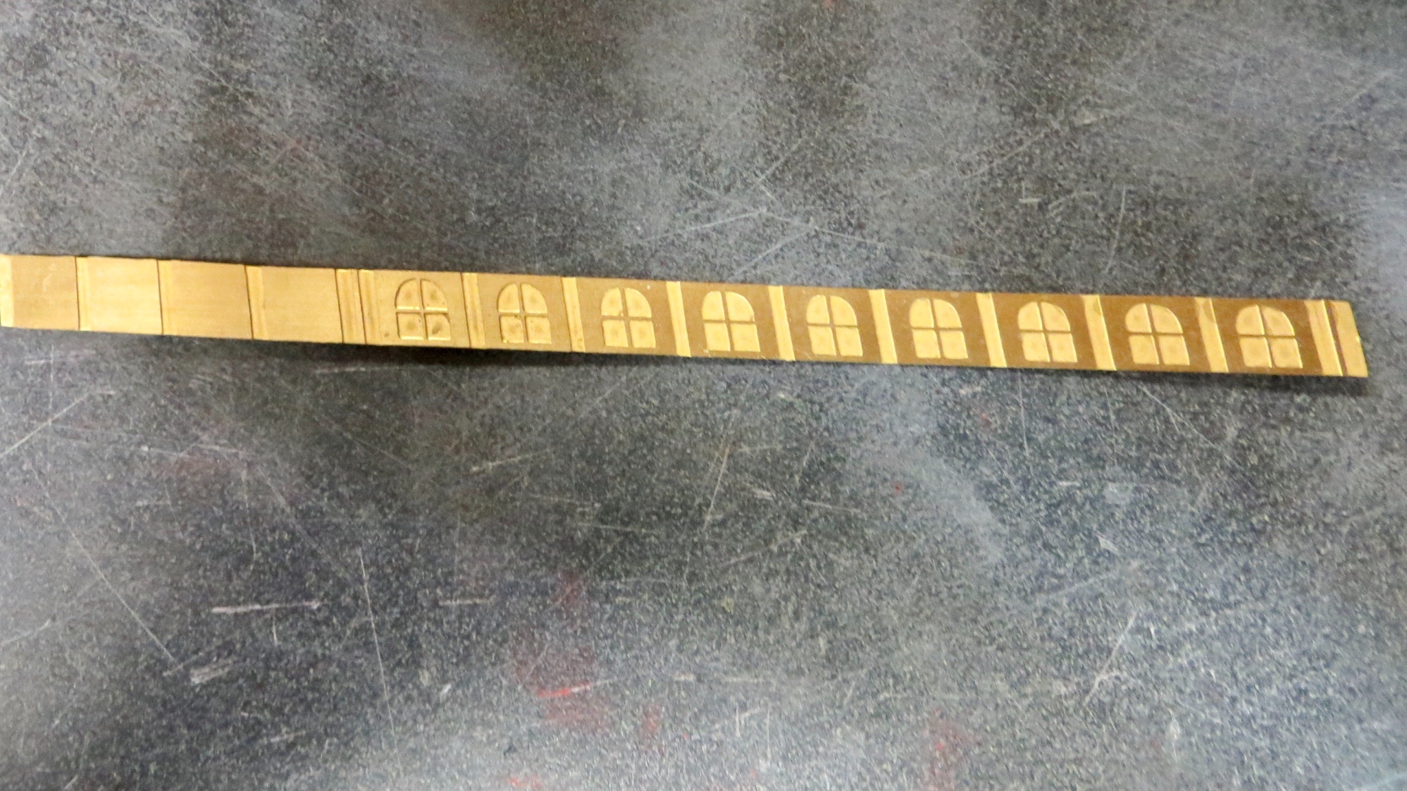
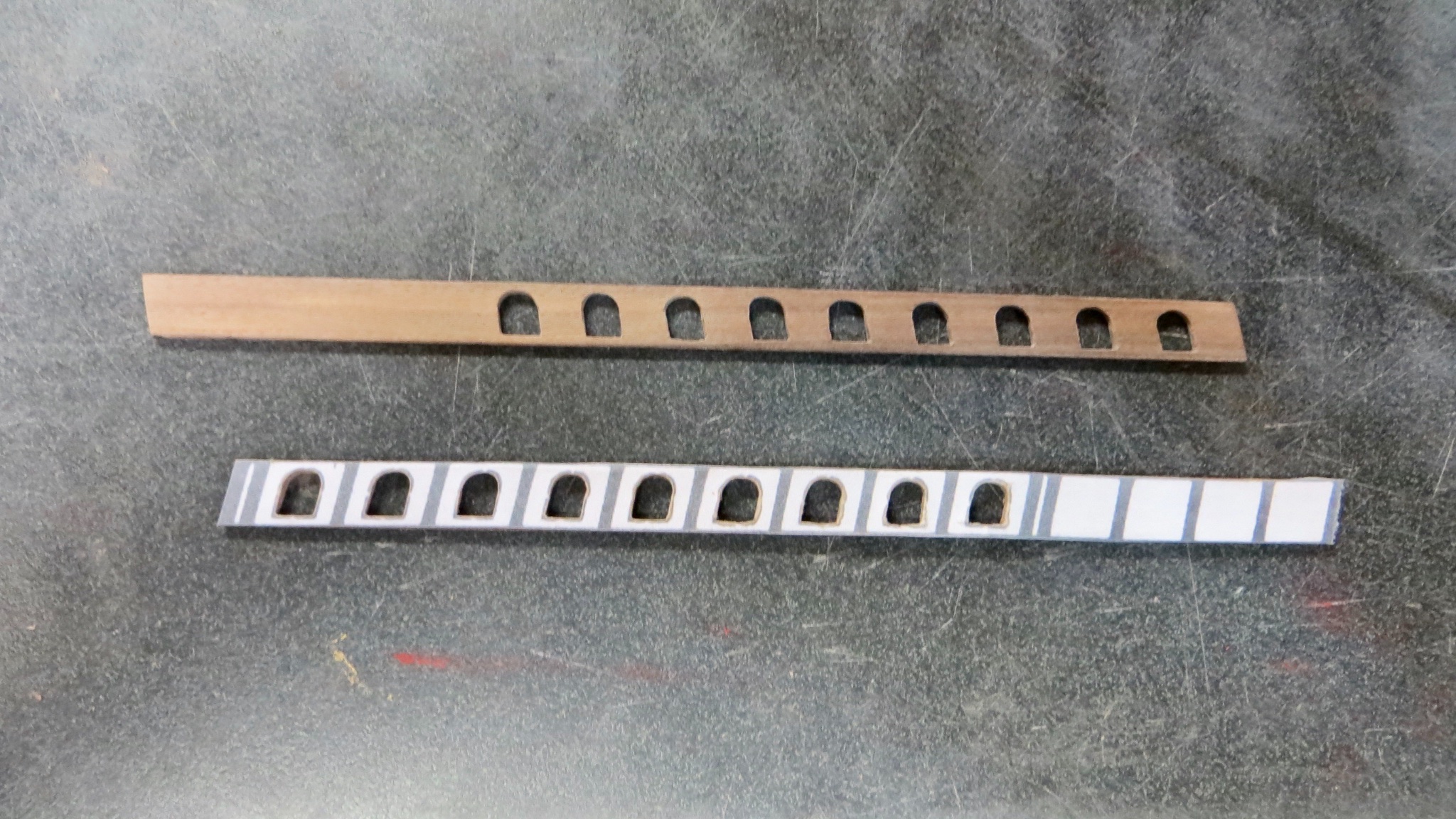
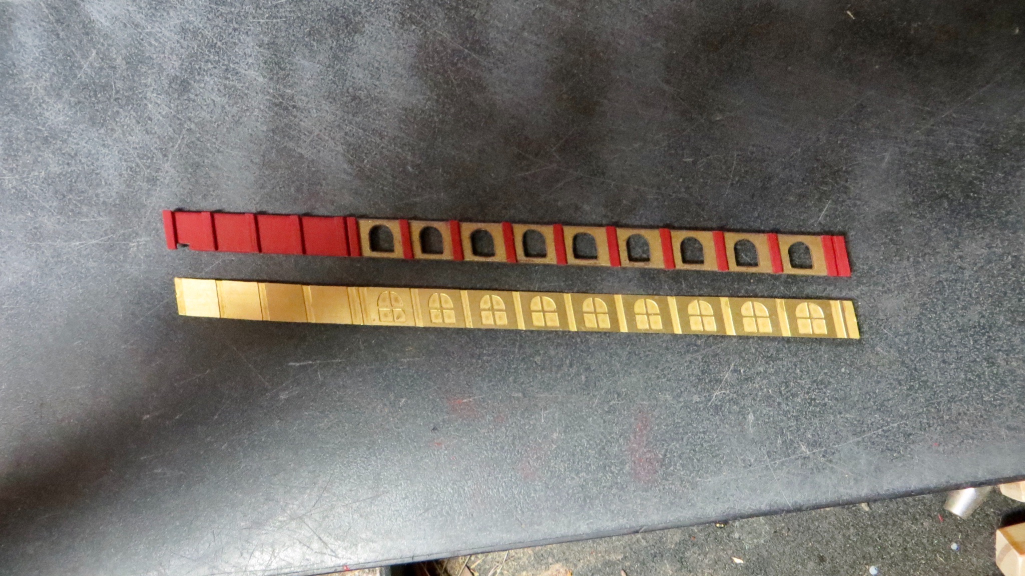
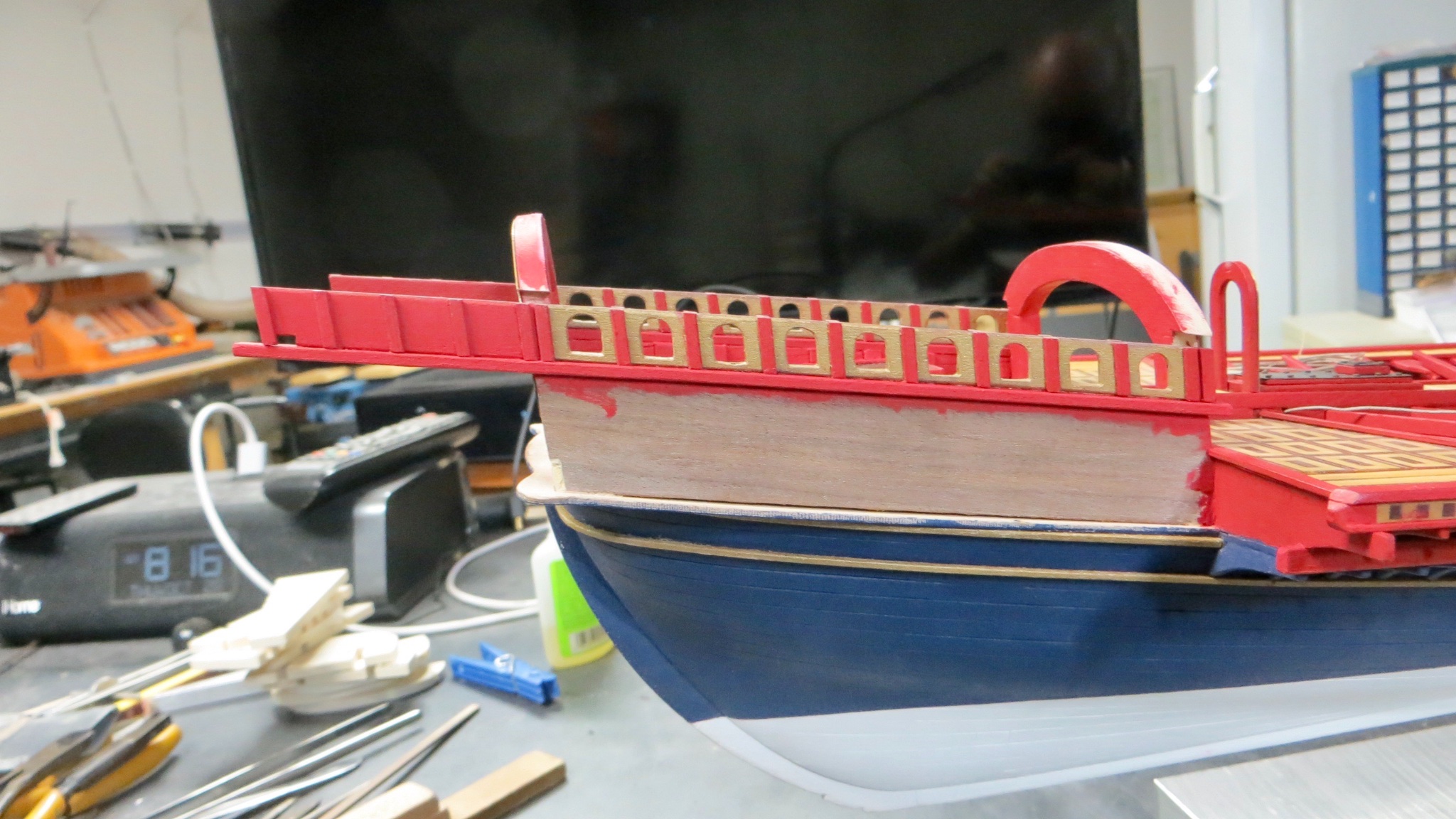
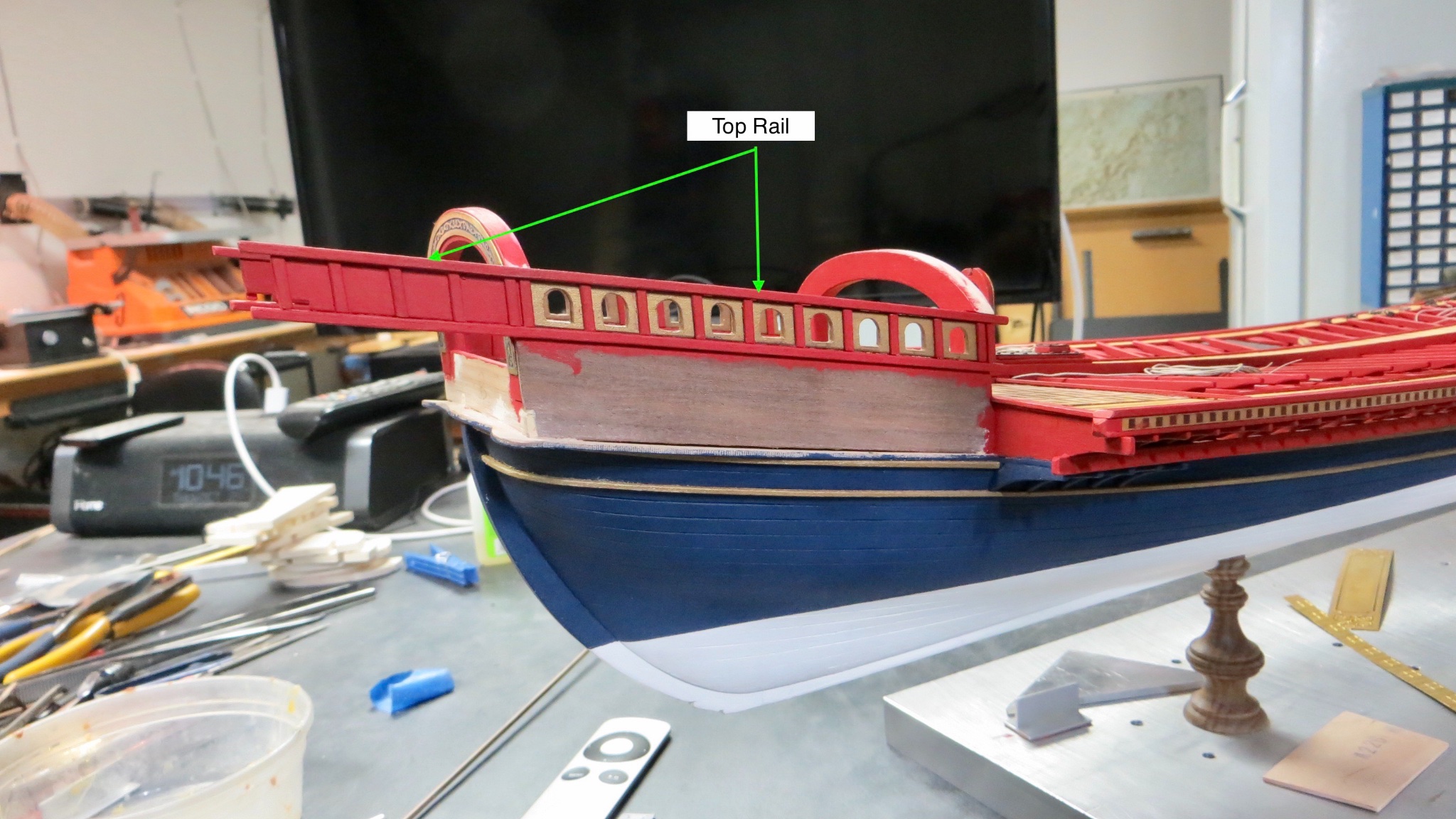
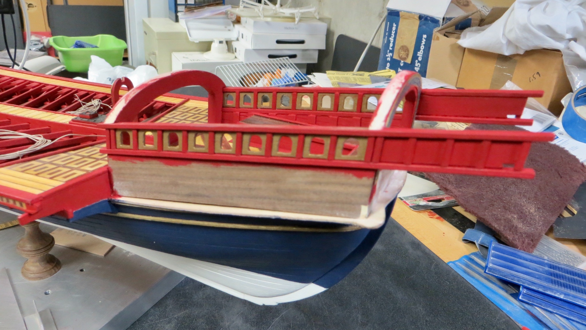
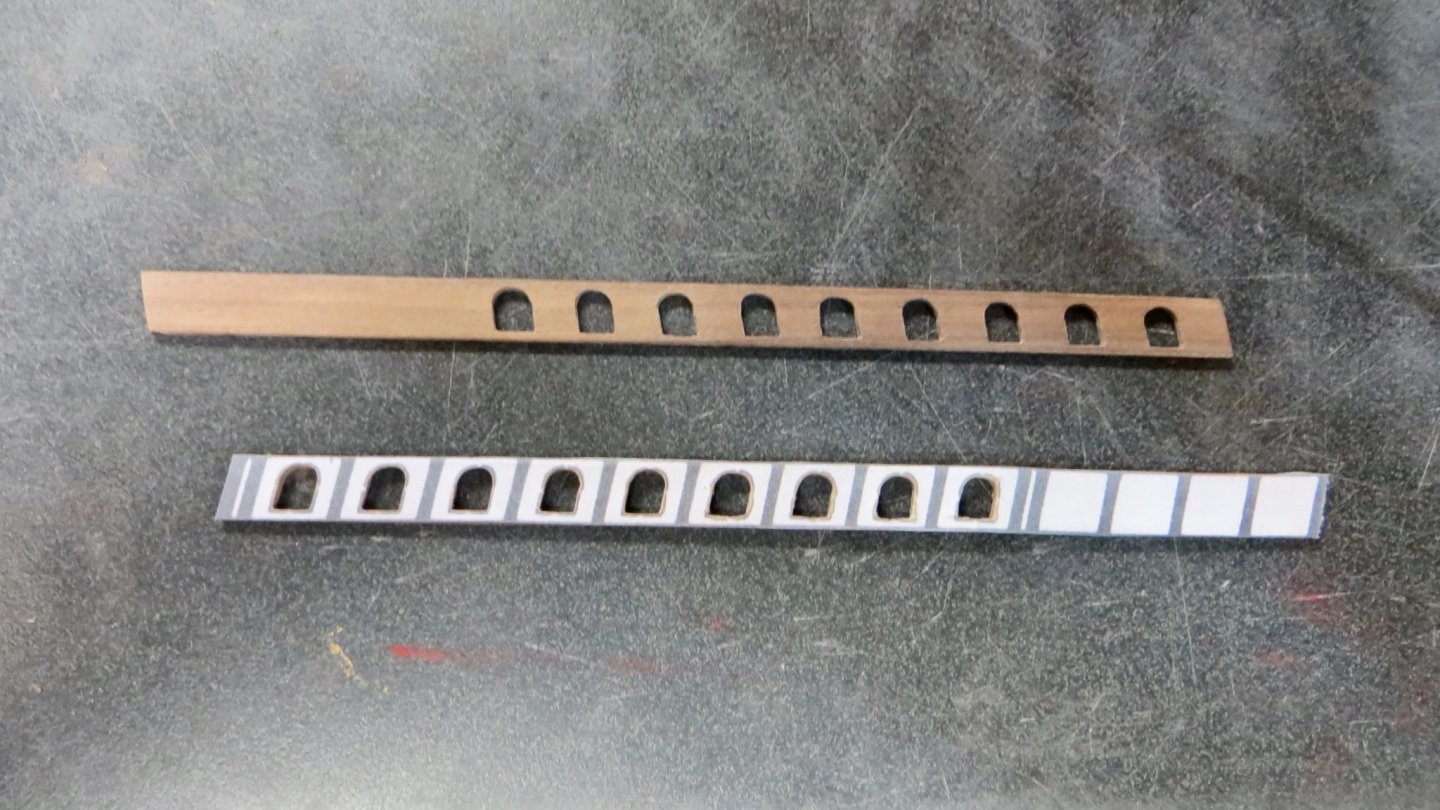
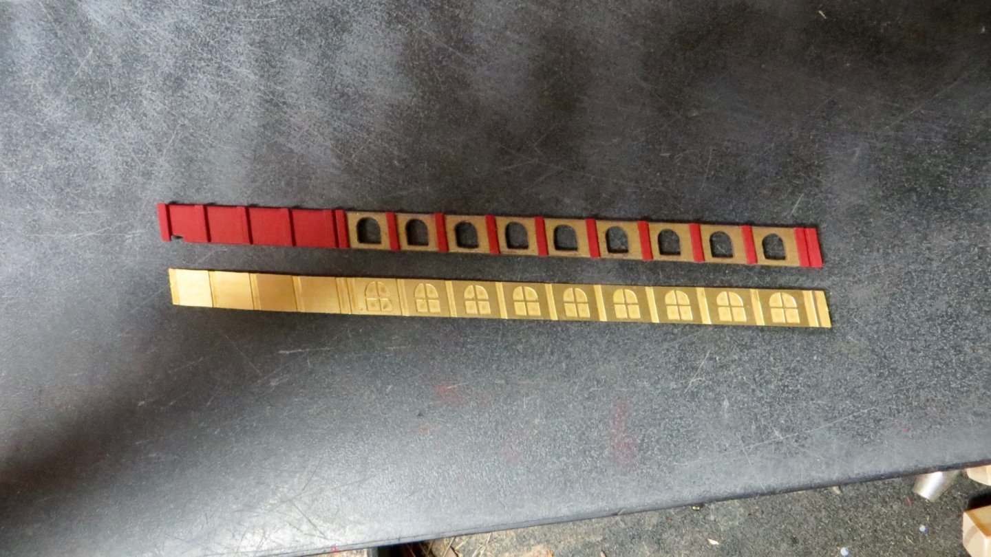
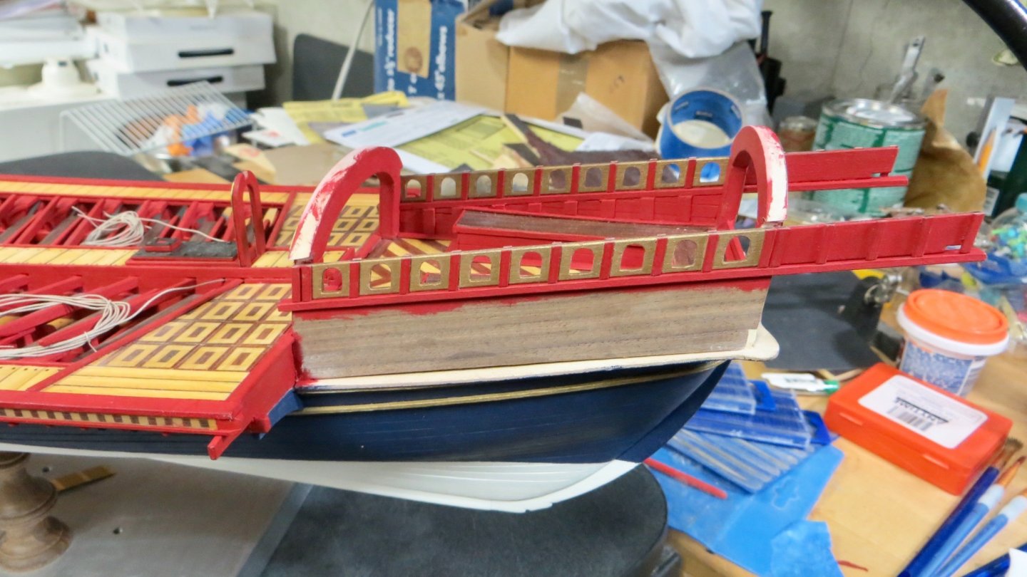
Hello, Continued on with the building up of the stern section of the model. The Corel plans show windows on both sides of the stern canopy area, above the lower railing (installed in the last post above.) The method the Corel plan calls for in making these windows is to attach a piece of wood on top of the lower rail and then glue this etched brass piece onto the wood and finally inserting wood posts in-between the etched windows. This issue I had with this was that while you would see the false windows from the outside, looking from the inside of the structure there would be no windows. The "Fleur de Lis" plan seem to show no windows at all, but just vertical spindle supports between the lower and upper railing. So, I decided to split the difference and made openings similar to the window shapes of the brass sheet, but left the ports open. The opening areas were painted an antique gold and the wood posts in red as shown. Installed on both sides. The ports (assembly) end flush with the bottom of the slots for the upper railing. View from port side and the interior of the starboard side. Views with the top rails installed. It is hard to believe, but there is another platform I have to work on making and installing next. This platform will sit between the port and starboard railings behind the stern arch. Thanks for stopping by, Frank


- 510 replies
-
- 8
-
-
- reale de france
- corel
- (and 1 more)
-
Excellent Job on the gun rigging Mark! Frank