


AON
-
Posts
2,596 -
Joined
-
Last visited
Content Type
Profiles
Forums
Gallery
Events
Posts posted by AON
-
-
-
They seem quite short for the capstan.
- Keith Black and mtaylor
-
 2
2
-
-
-
Regarding the name
I almost passed on looking at your build but then thought I was being stupid... after all, some ships were renamed two or three times. I had no idea what your ship might be. I am glad I took a peek.
Alan O'Neill
(From the Irish County Cork O'Neills)
-
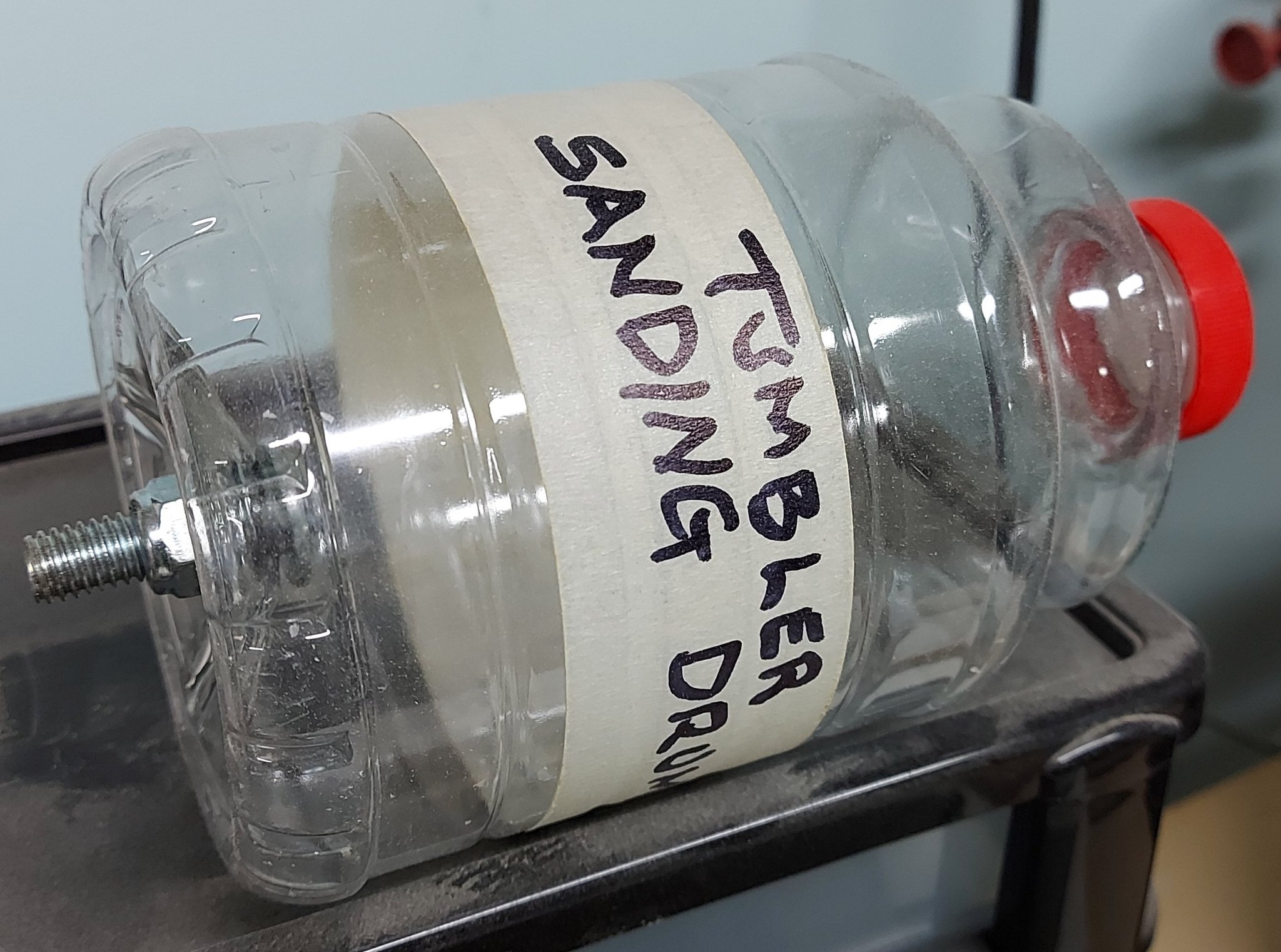
I had the idea weeks ago to make a sand tumbler. I saved a Orville Redenbacher Popcorn plastic bottle and screw top, and drilled a hole in the base for a bolt. I slipped a flat washer and O-ring over the bolt to seal it to the bottle base to keep the sand in.
I intend to get a small bucket of clean beach sand to use in the "tumbler", but haven't made it out to the shore of Lake Erie just yet (a 30 minute drive). I'd fill the container about quarter full to start and slip the bolt into my wood lathe set to it's slowest speed. Toss in some scrap bits with holes drilled through for a test run. To empty it I'd dump the contents back into the bucket with a screen/sieve to catch the parts.
I got the idea from fluidized bed furnaces and hopper screw augers used to remove debinded casting sand from Solution Furnaces. The former had sand flow like a fluid through every crack and crevice to heat treat gears, bolts, golf clubs, etc.. The latter seemed to be self cleaning via sand rubbing against the hopper and chute. So I imagine the sharp edges of the tiny sand grains would wear away and soften the edges of blocks, grooves and holes.
All I need now is the darned sand.


- modeller_masa, mtaylor, Canute and 1 other
-
4
-
FYI
The official response from DREMEL regarding their right angle drill attachment and their flex-shaft:
"Unfortunately, the right angle and the flex shaft are both attachments for our rotary tools, but are not compatible with each other."
Seems like a missed opportunity and short sightedness on the part of their engineering and marketing group... and so I suggested they might want to get their design group working on it. Of course I expect no action, but will be pleasantly surprised if a year and a half from now it is offered.
-
You, like others I follow, are well ahead of me (which is a good thing for me!). I was in the shop drilling holes with the dremel and flex-shaft when I took a break and read the update on your build from my phone. The dremel was dangling there in front of me. I did a quick search and some came up (but read on).
If you can use your homemade mini drill in the space, holding it in your hand (fingers?) I imagined a dremel attachment might not be much more difficult.
When I went upstairs later I did a better search on my computer and I am not certain they make one for the flex-shaft or for number size drills. They seem to only connect directly to the Dremel unit. I've contacted Dremel to ask. I have an ancient model that doesn't come up on their drop down menus for filling in their forms. Mine has replaceable brushes that I could not find on the website. YIKES. (I should have asked about that also).
-
I wonder if a dremel with a 3 foot flexible cable and a 90° drill attachments would be a good alternative.
FYI: My first flex cable burnt through the casing as I didn't know it needed to be taken apart and coated with grease occasionally.
The next one has lasted me 20 years.
-
-
-
I starting draughting in high school, grade 9. I had draughting classes for all four years. Went to college for 3 more years and was exempted from engineering drawing (draughting). On graduating I got a job in 1975 as a junior draughtsman, on a draughting board... and found out how much I didn't know. After years of training I was a senior draughtsman. We had tall sitting stools at our tables but rarely used them. We also did "napkin sketches"... now there is a lost art. One fellow made left and right gremlin foot print stamps (toes and all) from two erasers and when you came in in the morning you'd find graphite foot prints across your drawing sheet. I did pencil and ink drawings back then, but in came computers with AutoCAD.
I miss seeing the draughtman's dance: doing a few lines, standing back to review the work, stepping forward to fix or add to it.
With these computers everything was 2D and I eagerly climbed on board. No more graphite smudges on my drawings. The other plus was everyone's lettering was crisp clear and identical. It was beautiful until you had to revise someone else's drawing and found they used umpteen separate short lines when one long line would suffice.
I could never get use to sitting all day. When the option came to use a standing table I jumped at that. I would have loved to have a treadmill but the boss wouldn't spring for that. So I went for a walk every day at my break instead.
Then came 3D and my pet peeve for numerous short lines was exponentially increased as the darned programmes don't believe in a single line anywhere. Don't get me wrong, I love 3D draughting. If you've ever had to clean an area for clarity, it is a nightmare.
So retirement came just at the right time for me.
Now I use the Standard version of DraftSight (annual subscription) for my love of draughting, and the free hobbyist version of Fusion 360 for my love of 3D modelling (and preparing files for 3D printing). I had a 4 foot draughting table at home but sold that off years ago.
I loved SolidWorks but personally found AutoDesk Inventor was a better program... I simply cannot afford the expense in retirement.
- Rik Thistle, thibaultron and druxey
-
3
-
Like pry bars. Slipped under the gun and pivoted on the step of the carriage to lift the weight off the wedge.
Makes sense.
How would the gun be trained left or right when the trunnions are locked in place?
- mtaylor and Keith Black
-
2
-
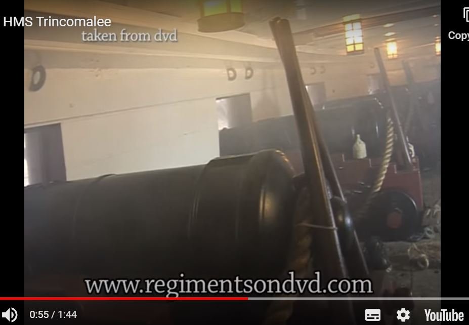
I stumbled across a video of the restored HMS Trincomalle and noticed two pieces of wood stood off the gun carriage, In a reverse V shape, resting against the castobell of the gun, lashed to the rope with "small stuff" (very light line).
Does anyone know the purpose of these?
-
I am making sawdust at the moment.
Will have a closer look in an hour or two.
Possibly Vahur will respond also.
- mtaylor and thibaultron
-
2
-
-
It is always the last place you look! You mentioned a contract... I finally went to look at my transcription for my build, and there it was with the definition added below (I did this a number of years ago).
[Page 12 - HMS Bellerophon]
STANDARDS ---- To have 12 standards on each side of the gun deck, the wood sided 12-1/4 inches; the foremoft (foremost) pair, and as many of the others, to be iron, as shall be directed; the up and down arm to reach the upper edge of the upper deck clamp, the other 4 feet 3 inches long, bolted with 7 bolts in each, of 1-1/4 inches diameter: the standards, both wood and iron, shall be all fayed on shoals of 3 inches plank, laid with tar and hair, or old canvas; to have a standard on the gun deck, against the head of the stern post, sided 13 inches, the fore and aft arm to be of fufficient (sufficient) length to receive a bolt in the third gun deck beam from abaft, to be fcored (scored) down on the gun deck beam 2-1/2 inches; the up and down arm to reach the upper side of the helm port tranfom (transom), and to have a carling from the beam abaft the mizzen maft (mast) to the tranfom (transom) 13 inches fided (sided), fcored (scored) up between the beams; and that the space from the lower side of the knee to the upper side of the carling, be filled up by fillings, let down between the beams before the knee is fayed, that the faid (said) standard may be bolted by one bolt in each beam, and one bolt between each beam, by bolts of 1-1/4 inches diameter, and to be well clenched under the faid (said) carling: to have a standard on the gun deck, against the apron, fided (sided) 13 inches, the up and down arm 5 feet 9 inches long: the other to be long enough to receive a bolt in the fecund (second) beam from afore, and to be properly fecured (secured).
I imagine most builds don't bother as, at the reduced build scale, they are so thin and (less the tar line) difficult to see.
-
Gary
Thank you.
I likely would never have found this.
-
Gary, I guess I was typing as you were posting!
I related the purpose of this shole/sole piece to the pergola timbers I've mounted on the flat concrete cap on top of the brick columns in my back yard.
I slipped a pieces of aluminum bar under the timber, on top of the cap piece, so when the snow melts the timber is raised slightly and can dry properly. Might have been over kill on my part but I was trying to avoid early rot as experienced in other wooden structures I've had over the years.
I would appreciate knowing as much about this item as there is to be learnt (learned?).
-
Thank you Garyshipwright for the description from Fincham.
I've looked in a half dozen of my books and a seaman's dictionary and have not found mention of the sholes/soles in this context. Also not shown in any diagrams/sketches.
I guess it was too small a detail to be noticed?
Does anyone have an image with this piece in it they can share?
(Druxey?)
I'd like to add it to the list of things I shouldn't forget... along with a map to find my list!
-
Did it simply lift the standard off the deck to keep it dry?
-
Your mini splices are impressive.
As a sea cadet I was taught to roll my finished splices on the floor under the sole of my shoe to tighten it up. You might try this with a piece of wood on top to see how it changes things.
On second thought, due to the reduced scale, possibly just rolling it between your thumb and forefinger 4 to 6 times might do the trick!
-
you should start a build log for this!
-
There is a wonderful paper on the properties of wood at:
https://thenrg.org/resources/Documents/articles/AnOverviewOfWoodProperties.pdf
on page 8 is an image regarding shrinkage and warpage
you might want to study it and then decide.
- Chuck Seiler, thibaultron and mtaylor
-
1
-
 2
2
HMS Thorn by Kevin Kenny - 1:48 scale - Swan-class - David Antscherl practium
in - Build logs for subjects built 1751 - 1800
Posted
Now that you're re-organized you'll never be able to find anything. 🤣