


AON
-
Posts
2,596 -
Joined
-
Last visited
Content Type
Profiles
Forums
Gallery
Events
Posts posted by AON
-
-
I assume you haven't used any CAD program yourself.
Prior to someone offering to do work for any compensation they would need to see the drawing(s) to appreciate the enormity of the task to be done.
Having done engineering drawings for clients for well over 30 years I can attest to having experienced the "what the client said. what the engineer heard. what the client wanted" phenomenon. It should be avoided or there will be a great disappointment for both parties.
Mark is correct in the steps to do the work.
Can you post photos of the drawing(s) you would like converted?
-
Bonjour Gaetan
I have a combination disk and belt sander on my worktable. I've use both regularly, the disk for end sanding small pieces and the belt set horizontally for larger flat pieces. It has an option to flip the belt vertically. I've never done this. After reading what you posted I think I will give it a try and find out for myself what you are talking about.
It will also give me an opportunity to clean under the belt!
Thank you for making me wonder about it. I am open to learning.
-
I had a couple good weeks of framing, followed by yet another needle in the left eye and a few days recovery.
Then I decided to work on something different for a change of scenery. Always nice to do that occasionally, finish something completely for a change as you can only fool yourself for so long that having completed yet one more frame is a major achievement 8*)
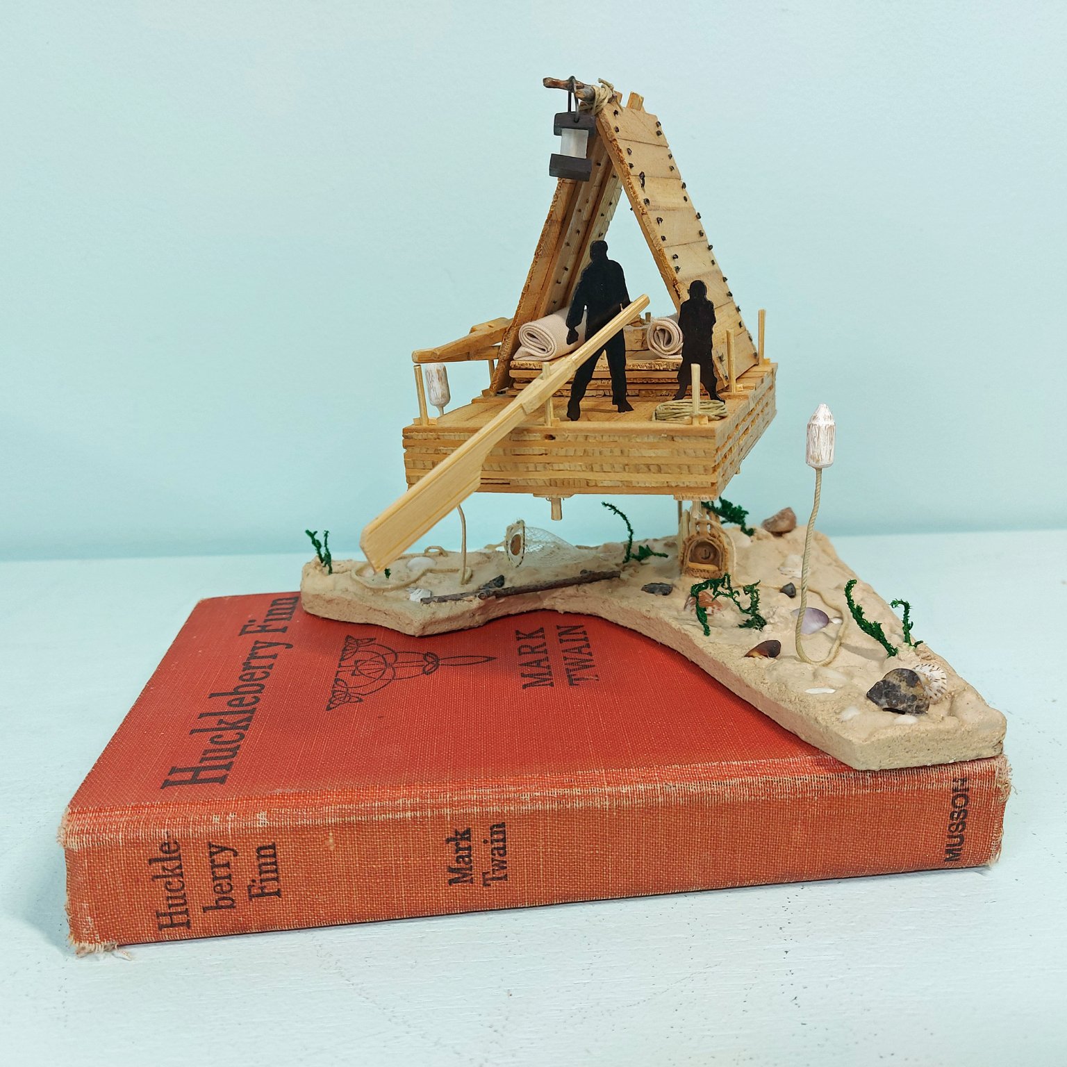
My Mississippi Plank River Raft (1830-1840) based on the description by Mark Twain in The Adventures of Huckleberry Finn.
The raft hovers above with the riverbed below (on top of the book). Crayfish and shrimp traps on the riverbed with wooden buoys floating above on either side of the raft at the imaginary water level.
Photo below.
Just needs a display case and name plate.
I was back onto frames yesterday.

- Old Collingwood, pjofc4, dvm27 and 15 others
-
 18
18
-
-
-
-
-
-
Per TFFM Vol 1 pg 257
Hanging Knee - fore side in fore body and aft side in aft body
that is to say hanging knees on forward beams go forward of the beam, and those on aft beams go to the aftside of the beam.
They bolt on the side to the beam not underneath so as to help prevent the beams from racking.
Lodging knees - aft side in the fore body and fore side in the aft body (just the opposite to the lodging knees otherwise they are on top of each other and that doesn't work very well)
The lodging knee end (running along the inside hull not the beam) was stepped to locked into a notch in the top outside corner of the hanging knee.
Hope you can understand this... that is to say that I hope I did a half decent job trying to describe it.
-
-
Peter
Not to name drop..... David Antscherl (in our local model club) once showed me that a dab of wood glue in the crack and a light sanding to move the sawdust into the glue made the crack disappear like magic.
Of course, he has a magic touch, and years of experience!
Try this on a test set up of two pieces of scrap before doing it on your model to see if it works for you.
- bruce d, mtaylor, Ryland Craze and 4 others
-
7
-
I think the caulking and treenails look absolutely fantastic!
-
-
-
It may have been bees wax to get rid of the stray wild fibres. I do not know how to tell for sure. Possibly some others might know.
I take it you are attempting to clean the model.
I know there are people here that have done that and I suspect they do not use Murphy's Oil Soap but rather saliva on the end of a Q-tip to remove dirt and dust. It is long and arduous work but I am told is a better way.
Possibly someone more skilled can confirm.
Alan
-
Good morning Mark.
Yes that might have been a possibility except the timber body outline is from slicing the 3D model and then the centerline was sketched in, followed by the chocks and scarph joints on one side, then mirrored. So if my centerline was off the mirrored items would not have fallen inside the frame outline but rather crossing to be outside of it, and I hope I would have spotted that.
What is as bad as having traced this onto a piece of wood and cutting it out and not noticing, I keep a log of my builds and bind them into a book for myself. I snipped an image of frames off my drawing and copied it into my log quite some time ago. It just so happens it was this frame and it's mate. I didn't notice it then either!
I must have sketched it once wrong, made the correction on the other side and then didn't delete the original and mirror the proper. It is the only thing that makes sense.
I worked for someone whose favourite saying was "it is what it is". I argued "it is what you make it, and if you choose not to change the outcome, then you choose what it is".... I choose this to be correct.
- garyshipwright, bruce d, druxey and 1 other
-
4
-
I am eager to read what others might say regarding CA so I am following this thread.
regarding deck planking nails. What era/type build are you working on as some nails were in countersunk holes and wood plugs driven in above them.
I've read some people simply use a sharp pencil to leave a graphite dot... as an old draughtsman I always smugged my lines so I wouldn't do this. You might try it on a piece of scrap then test with a layer of poly.
I've also seen black monofilament fishing line glued into drilled pockets to simulate the bolt. I am doing this on my frames and I draw the fishing line through sand paper to rough it up so the glue will grip. This is a lot more work than a pencil dot.
-
you might try this
https://anyconv.com/jpg-to-dwg-converter/
I've not used it and have no idea if it is any good
Maybe you can post a review?
-
The weather is beautiful and the leaves are falling.... six bags filled from raking, and the grass is cut for the last time this year.
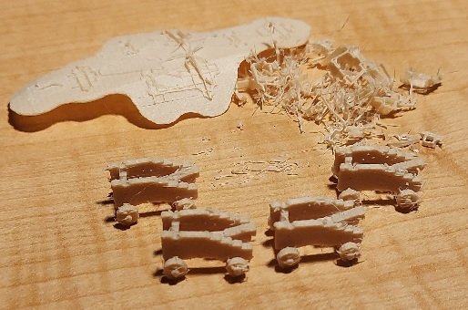
I am just this moment printing the last set of four gun carriages. They will need to be cleaned up but I will wait until my next eye needle on December 1st as I won't be down in the shop for a few days afterwards.
Today I discovered something that defies explanation.
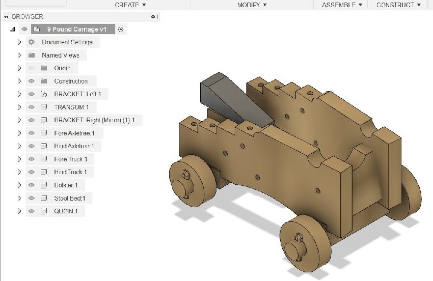
The printed template for the floor of my frame L-Forward is too long on one side. But the PDF of the drawing from which they should have been printed is correct as you can see in the images below. This suggests I supplied the wrong PDF to the printer. I cannot understand how the template was made wrong as the sketch on the 3D model was drawn on one side and mirrored to the other side, plus the original PDF is correct! Definitely a head scratcher.
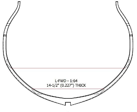
The above image is from the PDF and is correct. I added the red lines to show the proper alignment from port to starboard.
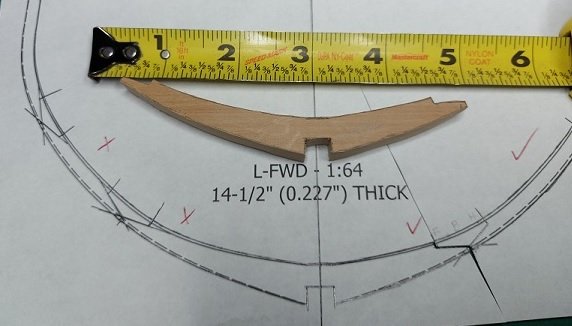
Here you can see the incorrect floor (one side longer than the other) with the piece cut out from a tracing.
How could I not have seen this earlier???
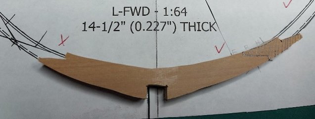
I've traced the correct location onto the floor and will cut it back.
Luckily I traced the 1st futtock from the proper side of the template so they are cut correctly.
-
Sorry but I cannot comment on whether spraying with anything to protect from scratches is a good idea or not.
- popeye the sailor and pwog
-
2
-
Will you be building a case for it to keep the dust off and prying little fingers away?
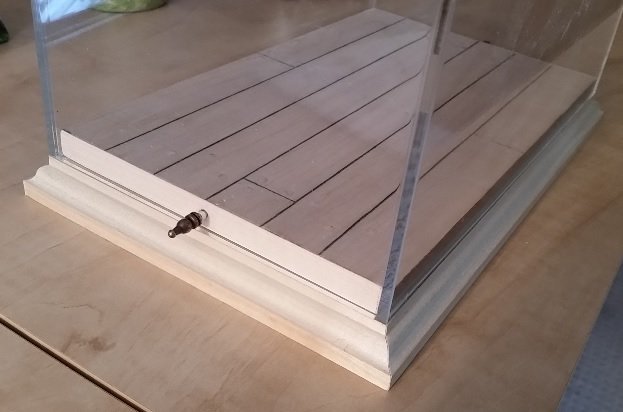
If you do I made my base and had the acrylic cover made locally. Unfortunately I did not have the foresight to give them the base so their part did not fit snuggly so I needed to make adjustments to my base.
I also added a locking pin on each end through the acrylic into the wooden base so if someone picked up the display case by the "glass" it did not fall apart.
I used ornamental pins cut from kitchen cabinet hinges (bought for the purpose, not taken from the kitchen cabinet) for this task.
-
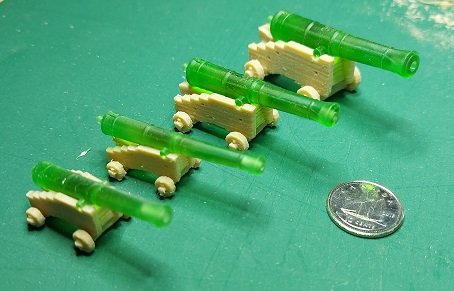
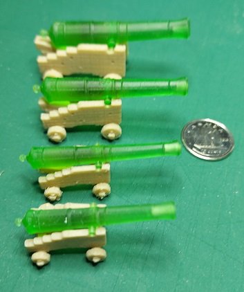
Here are the three sizes of carriages with the four sizes of guns in place.
They fit quite nicely without any fiddling and fudging.
Gundeck: 28 each x 32 Pdrs (9'-6" long cannon)
Upper Deck: 28 each x 18 Pdrs (9'-0" long cannon)
Quarterdeck: 14 each x 9 Pdrs - Short (7'-6" long cannon)
Forecastle: 4 each x 9 Pdrs - Long (8'-6" long cannon)They have been cleaned up slightly with pliers, scalpel, and a finger nail file.
I am awaiting the delivery of a new set of needle files so I can do a better job of it.
-
-
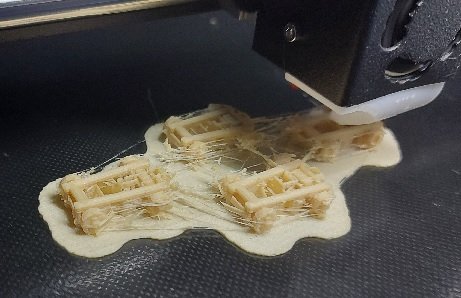
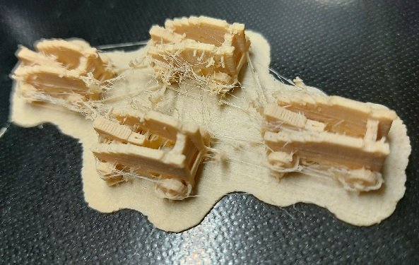
Yes that is an option if individual components will not print properly. I created the model in components so I would have that option but it was not the problem. The printer has sensors that alarm if it runs out of filament but not if the filament stops moving or feeding.
My problem was that nozzle clogged. I installed a 0.4 mm nozzle and all four carriages were printed successfully. The trucks (wheels) are a more perfect circle so I will stick with this size. I've made 3D models for the other two size carriages and will print out one of each and fit them with a cannon before I print out all 28 of each.
Here is the result of yesterdays success. They need more cleaning up but you can see how they turned out. The slightly larger nozzle uses more material so the cost increased from 16 cents for 4 to 18 cents for for... still quite cheap.


New Bedford Whaleboat by Mike_In_RI - FINISHED - Model Shipways MS2033 - Scale 1:16 - Small
in - Kit build logs for subjects built from 1851 - 1900
Posted
I always seem to stumble onto these beautiful builds too late!
I made a note regarding your comment on bending maple versus boxwood in post #12. This is helpful info.
I am also a fan of modifying the nose of wood clothespins to clamp in difficult spaces. Your long nose version in post #24 is something I hadn't envisioned and it will also be a handy addition to my collection.
The wrapping of the tangs of the oarlocks with small stuff was something I hadn't seen before. I imagine it saved the oars from wearing prematurely rubbing against the harder metal surface. I do know that the holes at the ends of the oarlock tangs were to close the gap with waxed whipping (small stuff) so the oar would not bounce out in rough weather. In my limited experience (sailing and pulling 27 foot whalers and 32 foot cutters) the post of the oarlock had a hole also and small stuff was secured to it and the other end to riser (that the thwart rests on) so they did not get lost at sea. The line was long enough that the oarlock could be removed and stored dangling inboard. I can see in the sketch in your post #93 that yours had this hole.
Your metal work is amazing, from the pail and barrel bands to the anchor! Then you actually did and eye splice in the bow rope!
Thank you for sharing. I learnt quite a bit.