


AON
-
Posts
2,596 -
Joined
-
Last visited
Content Type
Profiles
Forums
Gallery
Events
Posts posted by AON
-
-
Thank you for the well wishes everyone.
Dan
I've seen some 2D drawings of the mast pieces and stepped sections but no 3D renderings. I know some people have some trouble understanding more complex 2D drawings... and I am an avid fan of 3D models inserted into a 2D drawings . IMHO they add exceptional value at no extra cost!
Please let me know if you stumble across a model. If not I might have a stab at it down the road.
-
So much happening.
First I've added cyclone separators to my shop vacuums... more on that later.
Got everything ready to begin the square frames... hoping they will be easier especially when I can see clearly.
Tomorrow I go for surgery on my left (worst) eye. Then in about 5 weeks I get the other one done. I can't wait to see clearly again. Possibly I will be able to see the royal cypher on my 3D printed 9 pound gun barrel in the dark display case after all!?!
-
-
-
Without having experienced it, my technical training in fluid dynamics suggests that with the thickness of the rudder blade and the sharp change in shape (tail end of the blade) there would be considerable turbulence experienced which would be felt back through to the tiller, possibly resulting in shaking things up a bit.
I am certain each country did "borrow" any improvements in design that they discovered in captured warships of the time, and it was a busy time full of design changes.
Kurt, although I look forward to reading a short synopsis on the subject here, I appreciate the availability of the full article and will be getting it.
Thank you.
Alan
-
It has been awhile and much has happened. It is very warm in the Niagara Peninsula but I don't want to complain too loudly as winter is coming sooner than we'd like.
I hope everyone has been well.
I am just about done my fairing but continue to drag my butt. Recently I found tools and methods that work for me. A short bow sander for the outboard side and a 3 inch piece of foam pipe insulation onto which I wrap my sand paper for inboard and finishing the outboard. This last one is quite comfortable and contour friendly. I find the bow sander a bit monotonous and hypnotizing... had to give myself a good shake now and then to assure I was paying attention to the work at hand.
It has become difficult to see any close detail as my left eye is completely foggy (vision gone) and my right eye following it more quickly than I like. I hope to have cataract surgery to correct my vision issue before winter. Measurements have been taken and I await a phone call to schedule the event so long as day surgery isn't cancelled again due to any covid outbreak.... I still get a darned eye injection every 10 weeks to boot! Hopefully that will be done with soon.
-
After 3 years working on a side project, I have finally completed the transcription of every newspaper article I could find mentioning the very first HMS Bellerophon, her crew, and builder.
The 156 typed pages contain more than 520 items, from 84 different newspapers, covering the years 1731 to 1836. The last 63 items being the period serving as convict hulk. Through calls at various ports, weather, court martials, the Haitian Revolution, battles (Retreat of Cornwallis, Trafalgar, Nile), providing protection off Newfoundland (where I am certain my ancestors saw her), the capture of Napoleon, escape of convicts, attempted murder of the captain, including the builders marriage, bankruptcy and death. Then finally her being ordered to be broken up. There is even the false reference to an earlier bomb ketch of the same name.
It is now being reviewed. If anyone is interested in receiving a copy, please PM me with your e-mail address and I will send you a PDF. It is FREE, no charge, as I cannot imagine there being a very large group interested in this collection, so attempting to sell it would be foolish.
This will be Volume 2 of the book to accompany my build.
Volume 3 will be a record of the journey of the build itself... which I admit is moving at a snails pace.
-
Spritsail and spritsail topsail yard arm BANDS and EYEBOLTS
From Steels mast making 1794 plate 1, or Ree's plate VIII, we can see the image of the spritsail yard. There are eyebolts and metal bands at each end of the yard arm. The bolts measure approximately 1 inch (25mm diameter) which at 1:64 scale is 0.0156 inches (0.04 cm). The copper wire I used is 0.02" (0.05 cm) diameter which makes it 1-1/4" (3 cm) at 1:64 scale.
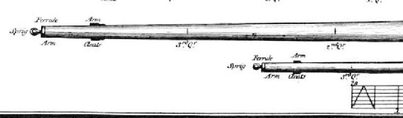
First I added the metal bands at each end of the yard arms. The metal band is about 1-1/2" to 2" (3.8 to 5 cm) wide as best as I can measure. The extreme end of the yard measures 7" (18 cm) diameter on the larger yard and 5" (12 cm) diameter on the smaller. To scale these are 0.11" (3 cm) and 0.08" (2 cm) diameter . They are much too small for me to roll a copper strip and solder, so I used the method suggested in The Fully Framed Model (TFFM). I took a sheet of white 20 lb bond paper (regular photocopy or printer paper) and coloured a small portion with black permanent marker. I turned it over and coloured the other side so the ink would soak through completely. Having had the ink soak through meant I would not have a white edge after cutting the strip. I then cut a strip about 1/8 inch wide (3 cm), applied diluted glue to both sides and applied it to the yard. It did overlap to create a bit of additional thickness.
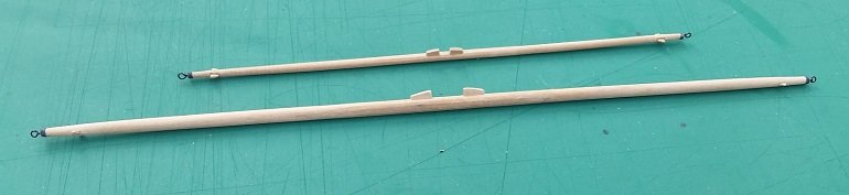
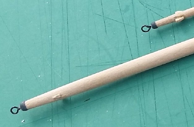
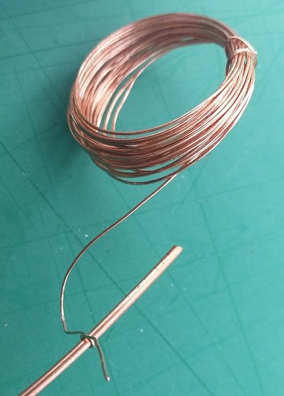
To make the eyebolts I wound the smaller wire around a 16 gauge (0.064 inch or 0.16 cm) wire to form the eye. At 1:64 scale this is a 4 inch (10 cm) inside diameter (ID) eye. Although the Ree's/Steel's drawing suggests smaller ID, I could not imagine a smaller hole in an eyebolt on a yard arm on a ship tossing at sea. I pulled this tight against the mould wire with pliers to get a good circle shape. The overwrap was cut back and adjusted to contact standing end as solder will not fill gaps.
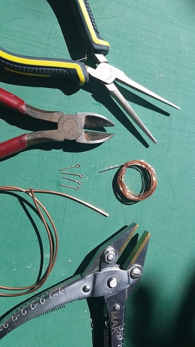
I found my parallel pliers were the perfect tool to re-straighten this tiny wire as it grips the complete length rather than pinching one end. (Thank you Druxey!) I could have rolled it out but might have damaged the bent eye.
I used a copper-phosphorous solder (thanks to Ed T in his post of 4 April 2014 in his build of HMS Terror on this forum) as I had bought it back in 2016 for this build and had not yet used it.... has it been that long? This will be used in lieu of silver solder as it is less pricy and chemically blackens well as it is copper based. I do not have silver solder. I could have used regular plumbing (soft) solder on these eyebolts as they will not be under any stress nor will they be chemically blackened.
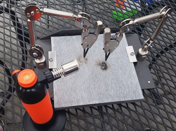
I hauled out my never used butane torch and GRS soldering station (Gesswein Canada)... It took awhile to realize my first problem was the torch was empty... luckily I had purchased a refill bottle way back when I got the torch. Thanks to a soldering display by Ray Peacock of our local club I saw the usefulness of the soldering station and so bought one and have had this sitting at the ready for the better part of a year.

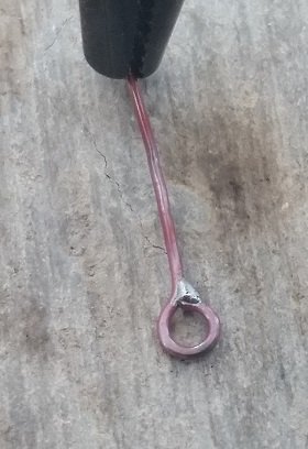
My first two attempts at soldering were terrible. I've soldered copper pipe in my home but this is different. The hole or void in the eye plugged up completely on both and I disintegrated (melted) the first. I found that if I cut a tiny piece of solder, warmed up my eyebolt and moved the piece of solder against the joint it would get sucked in. I then turned it over and re-heated to try to eliminate any blobbing. The copper wire was blackened with permanent marker as I was reluctant to chemically blacken something so tiny as the process is actually oxidation or surface corrosion and I had already vapourized one eyebolt. Possibly I shouldn't be concerned, but this is what I did and why.
Using a #70 (0.028 inch or 0.07 cm diameter) bit and pin vise I drilled holes into the each end of the yard arms, centered as best I could. I trimmed the standing end of the eyebolts (about 1/2" or 1.3 cm long) and slipped them into the yards. Presently they are dry fitted.
If experienced modellers tell me the eyes are too large I can take these out and replace them.... should I?
I've yet to make blocks, sails, rope, and attach them to the two yards. The sails will be furled. The parral trucks and ribs are made for the spritsail topsail yard but I do not have the proper rope as yet.
Everything is presently back in the storage box to keep it safe.
-
To all that have been enjoying these posts, I have run out of papers to review. I hope others might add to this topic and keep it going.
After about 3 years of working on this project, I have completed my collection of posts pertaining to the first HMS Bellerophon, her crew, the builder, and her time as a convict hulk (re-named Captivity). 156 pages, 520 items, 84 different papers from 1731 to 1836. Through calls at various ports, weather, court martials, the Haitian Revolution, battles (Retreat of Cornwallis, Trafalgar, Nile), providing protection off Newfoundland (where I am certain my ancestors saw her), the capture of Napoleon, escape of convicts, attempted murder of the captain, including the builders marriage, bankruptcy and death. Even the false reference to an earlier bomb ketch.
Give me any date and I can tell you what she was doing!
It was quite a ride for me and will become book 2 of 3 accompanying my build.
Now it needs to be reviewed and corrections made.
-
-
and time moved on... progress in 1815 with steam boats

- bruce d, druxey, paulsutcliffe and 1 other
-
 4
4
-
and... wars are over. So do what ever you want, the Admiralty needs a break - 1815

- paulsutcliffe, druxey, mtaylor and 1 other
-
4
-
Thank goodness he didn't decide to go down with the ship - 1815
- mtaylor, druxey, paulsutcliffe and 1 other
-
4
-
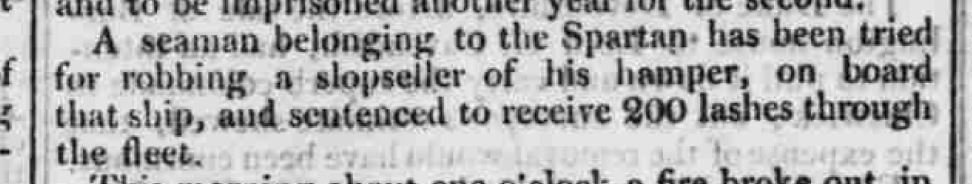
-
LASHES THROUGH THE FLEET: A form of punishment in the old days of the British Navy for the more serious crimes committed on board. It could be awarded only by sentence of a court martial. The man undergoing sentence was placed in a boat in which a ship's grating had been lashed upright across the thwarts, and rowed alongside each ship lying in harbour. While bound to the grating he was given twelve strokes with a cat-o'-nine-tails by a boatswain's mate of the ship off which the boat was lying. After each infliction of a dozen strokes a blanket was thrown across his back while he was being rowed to the next ship, and it was usually necessary to ‘comb the cat’. A naval doctor was always in attendance in the boat to make certain that the man undergoing punishment was fit to receive further instalments of his sentence as he came alongside each ship. In each ship visited the crew were mustered on deck and in the rigging to witness the punishment, drums on board beating out the ‘Rogue's March’ as the boat approached.
- paulsutcliffe, bruce d and mtaylor
-
3
-
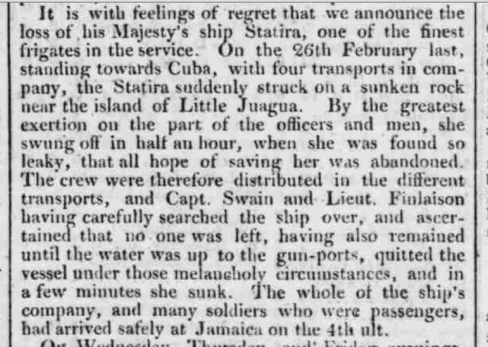
And this is one mans story of what happened... - 1815
.JPG.7ac875d6f5b789fce545cade01950955.JPG)
.JPG.ebd70870a1f0a2b0a2fe931408f54360.JPG)
.JPG.5557e2d8b53dbdfb27c91d64e67dc117.JPG)
- paulsutcliffe, davyboy, mtaylor and 2 others
-
5
-
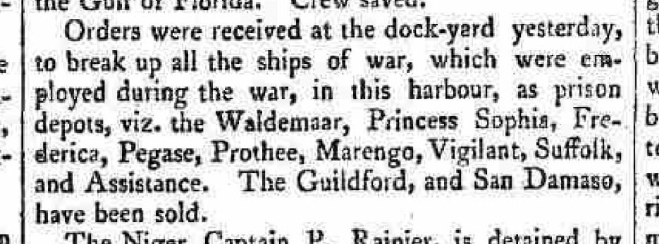
Oh, what to do with all this surplus stuff? - 1814
- paulsutcliffe, mtaylor and druxey
-
3
-
I hear a new verse in my head to 'What do you so with a drunken sailor?'
When I took my PL course the first thing they made us do a 6 AM was jump off the jetty, be it high or low tide, didn't matter. And I can attest to the fact that looking down was worse than looking up (for me). Then they made sure we could tread water for a minimum of 30 minutes. And they didn't care that the water was damn cold or that the boats officer had a photo of a 15 foot shark they'd caught off that jetty hanging on his wall. Then they taught us to make a flotation device from our trousers to buy us more time.
Of course that only counts in a day and age where ships can turn on a dime in most weather conditions, otherwise I suppose, you are fish food. I've read enough 200 year old publications now to know swim or not, your chances back then were from not good to really. really bad..
-
-
and... what an idiot.. 1813
-Mar1813.JPG.5c1d1afa9db278c081111f7fbfdb7641.JPG)
- mtaylor, paulsutcliffe and bruce d
-
3
-
We will never see such a sight again - 1813
-Feb1813.JPG.c471e7a204ed1b57e0ccaa6d884f5e17.JPG)
- bruce d, paulsutcliffe and mtaylor
-
3
-
We will never see such a sight again - 1813
-Sept1813.JPG.ef7355731c6f1a1432a27de9d74f5e35.JPG)
-
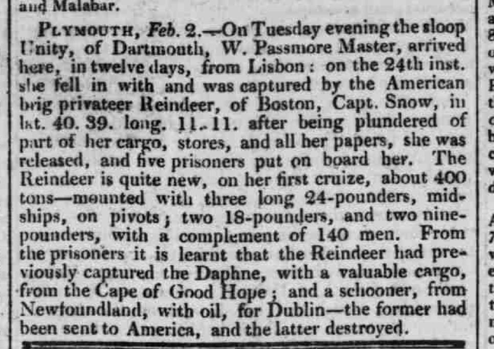
War of 1812 (1812 - 1815) between the USA and Great Britain fought in North America and the North Atlantic.
Here is a report from Lake Erie - 1813

- paulsutcliffe, bruce d, druxey and 1 other
-
4
-
Could they possibly be attempting to confuse the enemy... in this case the Americans.
There are three stories. Ignore the short middle one.
The true story is ... well, both of them.
It appears the Admiral couldn't make up his mind, plus, this story appeared in a British India paper, so by the time they printed it, it was old news.
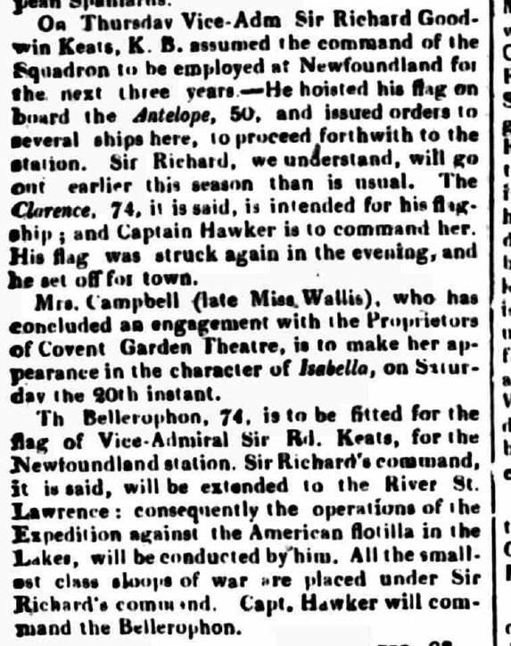
-Aug1815.JPG.208f9ee43b01c49d1b9b2cf466237f89.JPG)

HMS Bellerophon 1786 by AON – scale 1:64 – 74-gun 3rd Rate Man of War - Arrogant-Class
in - Build logs for subjects built 1751 - 1800
Posted
Good morning everyone. I had my eye surgery (cataract removal and new lens implant) last Friday and it has been amazing. The actual surgery was over before I realized it had started. The most painful part was when they removed the tape holding the IV plug in the back of my hand just prior to my discharge from the hospital. I cannot recall my vision being so vivid and crisp. Yesterday I went to the optometrist to have the lens removed from the frame as wearing my glasses with both lenses gave me a headache and simply ruined the view. I get the other eye done on the 25th of September.
Meanwhile I am not allowed to do quite a few things and one is to work in the shop... a sawdust issue.
So I've decided to work on my deck templates. There are five in total: roundhouse, forecastle, quarter deck, upper deck, and gun deck. I spent a part of yesterday refreshing myself with Fusion 360 and my 3D ship model. I pulled out my Museum plans and measured the height of each deck at their extreme upper surface forward and aft location. Then I copied my model and sliced it at the quarter deck so I had the outside perimeter of the deck (inside of the hull) identified. The result is below. Now I need to layout the deck framing to create the templates.
Prior to my surgery I added cyclone dust separators to my two shop vacuums. I found a supplier that stated the minimum kW rating required to work and then checked my shop vacuums HP rating (conversion to metric was necessary). The filters were constantly clogged and emptying them was messy job. The cyclone separator spins the dust around the outside cone of the housing to separate the dust with centrifugal force. It removes 98% of the dust per the specifications. The last 2%, a fine dust that is too light to drop out flows through to the vacuum filter... there was nothing seen on the floor of the vacuum canister.
I looked at a few YouTube videos before I began the process. The sparators were supplied with two couplings and hose clamps but as they are metric and my hoses are not I needed to purchase some additional fittings (flexible rubber couplings and hose barb fittings from Canadian Tire), plus I used some adhesive backed 1/4" rubber gasket material (McMaster-Carr) where the fit was still sloppy. I built a mobile deck for the smaller vacuum that moves around the shop, added casters that were horded from old tables or chairs, and a wall shelf for the stationary vacuum that is connected to the Lee Valley Tools dust collection system that was gifted to me by a good friend. I also bought four 5 gallon pails and two lids from RONA. One pail acts as a "cup holder" for the other pail, and the lid was cut out and drilled to mount the cyclone separator. The "cup holders" are screwed down and a hole is drilled through the deck to break the suction that normal makes it difficult to pull stacked pails apart.
They work like a charm!
Photos below and also a short video of centrifugal force at work.